Table of Contents
Advertisement
Quick Links
EM2RS Series
Modbus RS485 Stepper Drive
User Manual
For Models of EM2RS-522, EM2RS-556, EM2RS-870 and EM2RS-A882
©2019 Leadshine Technology Co., Ltd.
Address: 15-20/F, Block B, Nanshan I Valley, No.3185, Shahe West Road, Nanshan District,
Shenzhen, Guangdong, 518055, China
Tel: (86)755-26409254
Fax: (86)755-26402718
Web:
www.leadshine.com
Sales:
sales@leadshine.com
Support:
tech@leadshine.com
Advertisement
Table of Contents
Troubleshooting

Related Manuals for Leadshine Technology EM2RS Series


Summary of Contents for Leadshine Technology EM2RS Series
- Page 1 EM2RS Series Modbus RS485 Stepper Drive User Manual For Models of EM2RS-522, EM2RS-556, EM2RS-870 and EM2RS-A882 ©2019 Leadshine Technology Co., Ltd. Address: 15-20/F, Block B, Nanshan I Valley, No.3185, Shahe West Road, Nanshan District, Shenzhen, Guangdong, 518055, China Tel: (86)755-26409254...
- Page 2 Therefore, information contained in this manual may be updated from time-to-time due to product improvements, etc., and may not conform in every respect to former issues. Thank you for purchasing Leadshine EM2RS Series Products ◆ Please read this manual carefully before operating ◆...
- Page 3 EM2RS Modbus RS485 Stepper Drive User Manual Safety Precautions Overall Notes Do not remove the housing with the drive powered on. Cables. Connectors and optional equipment. Please disconnect the power supply for at least 2 minutes and make sure the ...
- Page 4 EM2RS Modbus RS485 Stepper Drive User Manual Precautions for Installation Please install the drive in a cabinet that provides fire protection. Electrical protection in the control cabinet. Please install the driver and motor in a position with sufficient weight ...
-
Page 5: Table Of Contents
Table of Contents 1 Introduction..............................- 1 - 1.1 Product Introduction..........................- 1 - 1.2 Features..............................- 1 - 1.3 Application Scenarios..........................- 1 - 1.3.1 Hands-on Tuning..........................- 1 - 1.3.2 Practical Application Scenarios...................... - 1 - 1.4 Check of Product............................- 3 - 1.4.1 Arrival inspection..........................- 3 - 1.4.2 Nameplate information........................ - Page 6 4.2 Modbus Function Codes (FC)........................- 14 - 4.2.1 Read Holding Registers FC= 03....................- 15 - 4.2.2 Preset Single Register FC= 06......................- 16 - 4.2.3 Preset Multiple Registers FC= 10....................- 17 - 4.3 Modbus & PR Parameters........................- 18 - 4.3.1 Basic Parameters...........................- 18 - 4.3.2 Input and Output Parameters......................
- Page 7 6.1.2 Operation of Trial Run........................- 45 - 6.1.3 Operation of PR Function......................- 46 - 6.2 Basic Operation of Serial Port Tools Software..................- 48 - 6.2.1 Preparation and Steps........................- 48 - 6.2.2 Operation Instruction Format....................... - 49 - 6.2.3 Command Cases of Modbus RTU....................- 49 - Appendix A Parameters List..........................
-
Page 8: Introduction
1.1 Product Introduction EM2RS Series are stepper drive based on standard Modbus RTU protocol, using RS485 communication can network up to 31 axes. They built-in PR feature with 16-segment position table (PR Mode) can save additional controllers in most of point-to- point applications, to greatly enhance system reliability and reduce the cost. - Page 9 EM2RS Modbus RS485 Stepper Drive User Manual The RS485 (Modbus-RTU protocol) communication triggers the drive's PR motion register, which can realize the drive's path motion. Both PLC and HMI have RS485 communication, so user can choose one or both. Using PLC can write more complex programs to let motion more intelligent, and the HMI can monitor and modify the drive parameters in real time.
-
Page 10: Check Of Product
EM2RS Modbus RS485 Stepper Drive User Manual 1.4 Check of Product 1.4.1 Arrival inspection Check whether the surface of the product is damaged or not during transportation. Check the nameplate models of the drive and motor are what you have ordered. ... -
Page 11: Parts Description
EM2RS Modbus RS485 Stepper Drive User Manual 1.4.4 Parts description 1.4.5 Accessories Information Need to Name Necessary Picture Description cost extra Tuning Cable CABLE-PC-1 cable (CABLE-TX*M*-BUS) Optional length: 0.1m, Network cable 0.2m, 0.3m, 0.4m, 1m, 1.5m, 2m, 3m,5m,7m, 10m,15m, 20m Note: (1) Tuning cable is not necessary, but it is recommended to order. -
Page 12: Dimensions
Please ensure grounding wires are securely connected 2.2 Dimensions Unit: mm (1inch=25.4mm) Figure 2.1: EM2RS series mechanical drawing 2.3 Installation Direction and Space The mounting of drive, wiring and motor should be under the regulations of EN 61800-5-1. ... - Page 13 EM2RS Modbus RS485 Stepper Drive User Manual Figure 2.2: EM2RS series installation drawing - 6 -...
-
Page 14: Product Specifications
EM2RS Modbus RS485 Stepper Drive User Manual 3 Product Specifications Don’t hot plug the motor wiring, encoder wiring and RS232 communication wiring during power on. Be sure to check the connections and make sure the power lead polarity is correct, or there ... -
Page 15: Wiring Instructions
EM2RS Modbus RS485 Stepper Drive User Manual 3.2 Wiring Instructions Figure 3.1 Wiring Instructions Note: (1) There are two RS485 communication ports above, one of them is input port which connects with master station or previous slave, and the other is output port which connects with the following slave. (2) Single-ended inputs I1, I2, I3, I4, I5, I6 and I7 connection types can be common-cathode and common-anode. -
Page 16: Interface Specifications
EM2RS Modbus RS485 Stepper Drive User Manual 3.3 Interface Specifications 3.3.1 Connectors Definition Figure 3.2: EM2RS series connectors Name Description Input power connector Motor connector I/O signals connector RS485 communication connector RS232 tuning connector Salve ID: SW1-SW5 DIP Switch Baud Rate: SW6-SW7 Terminal Resistance: SW8 3.3.2 CN1 &CN2 Input Power Connector... -
Page 17: Cn3-I/O Signals Connector
EM2RS Modbus RS485 Stepper Drive User Manual EM2RS-A882 Name Signal Description Motor phase A+ Motor phase B+ Motor phase A- CN1& Motor phase B- 18-80VAC or 24-100VDC; No polarity Note: When the user uses an AC transformer to supply power, be sure to use an isolation transformer to prevent electric shock or burn out the computer 3.3.3 CN3-I/O Signals Connector Name... -
Page 18: Cn5-Rs232 Tuning Port
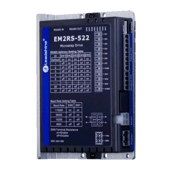
Name Signal 3.3.6 DIP Switches The EM2RS series drives use an 8-bit DIP switched to set Salve ID (also called Site Alias), Baud Rate and Terminal Resistance, they are shown as below: (1) Slave ID: SW1-SW5 (off=1, on=0) Slave ID... -
Page 19: I/O Connection
EM2RS Modbus RS485 Stepper Drive User Manual Note: (1) When the SW1-SW5 is default (all are on), the Slave ID can be configured by the PC software (2) Baud Rate: SW6 - SW7 Baud Rate 115200 (Default) 38400 (Factory) 19200 9600 Note: (1) When the SW6-SW7 is default (all are off), the Baud Rate can be configured by the PC software (3) Terminal Resistance Selection: SW8... -
Page 20: Digital Output
EM2RS Modbus RS485 Stepper Drive User Manual Figure 3.3: Input Interface Connection 3.4.2 Digital Output Figure 3.4: Output Interface Wiring Note: (1) The power supply (12-24VDC) above is provided by user, and if the polarity of power supply is reversed, it will damage the drive. -
Page 21: Modbus Rtu
EM2RS Modbus RS485 Stepper Drive User Manual 4 Modbus RTU 4.1 Communication Specifications Items Specifications Remarks Communication RS232 only for fine tuning RS485 and RS232 Port RS485 for motion control Baud Rate 9600/19200/38400/115200[bps] Parameter setting Synchronous Start / Stop Synchronization Mode Communication Half-duplex, Master-slave Mode... -
Page 22: Read Holding Registers Fc
EM2RS Modbus RS485 Stepper Drive User Manual Preset Single Register Writes to single holding register Preset Multiple Registers Writes to multiple holding register 4.2.1 Read Holding Registers FC= 03 Read Holding Registers Query (Master to Slave) Read Holding Registers Response (Slave to Master) Slave ID 00 - 1F Slaver ID... -
Page 23: Preset Single Register Fc
EM2RS Modbus RS485 Stepper Drive User Manual Slave Number Value of Address Value of Value of Value of Value of Description bytes returned 0x01BC 0x01BD 0x01BE 0x01BF 0x01C0 0x01C1 Note: (1) The above example shows reading the value of Pr5.22, Pr5.23, Pr5.24, their corresponding address are 0x01BD, 0x01BF, 0x01C1. -
Page 24: Preset Multiple Registers Fc
EM2RS Modbus RS485 Stepper Drive User Manual Master->slave data Message: 18 01 22 11 06 06 Description Address Function code Register address Write data CRC check code Slave>master data: Message: 18 01 22 11 06 06 Description Address Function code Register address Write data CRC check code... -
Page 25: Modbus & Pr Parameters
EM2RS Modbus RS485 Stepper Drive User Manual (means path 1); (2) The data type of parameter is 32bit, which include high 16bit register and low 16bit register.usually , we use low 16bits only, but it needs to take the high 16 bits as beginning when we read/write multiple parameters continuously. 4.3 Modbus &... - Page 26 EM2RS Modbus RS485 Stepper Drive User Manual bit0: over-current ( Cannot be changed) bit1: over-voltage bit3: ADC sampling failure bit4: Locked shaft alarm bit5: EEPROM alarm bit6: Auto-tuning alarm 0x0177 Pr4.27 Bus voltage 0-65535 0.1V 0x0179 Pr4.28 Digital input statue Bit0-Bit6: SI1-SI7 0-65535 0x017B...
-
Page 27: Input And Output Parameters
EM2RS Modbus RS485 Stepper Drive User Manual Write Function value 0x1111 Reset current alarm 0x1122 Reset history alarm Save all parameters to 0x2211 EEPROM Parameter reset(exclude 0x2222 0x1801 Control word motor parameters) All parameters are reset to 0x2233 factory Save all mappings into 0x2244 EEPROM JOG CW (Need to write... -
Page 28: Smooth Filter Time Setting For Digital Inputs
EM2RS Modbus RS485 Stepper Drive User Manual Trigger Command CTRG 0x20 0xA0 Command Complete CMD_OK 0x20 0xA0 Homing Trigger HOME 0x21 0xA1 Path Complete MC_OK 0x21 0xA1 Quick Stop 0x22 0xA2 Homing Complete HOME_OK 0x22 0xA2 JOG+ JOG+ 0x23 0xA3 Alarm 0x25 0xA5... -
Page 29: Status Monitoring Parameters
EM2RS Modbus RS485 Stepper Drive User Manual Register Value Filtering time (unit: ms) 0000 0001 0010 0011 0100 0101 0110 0111 1000 1001 Reserved bit, write 0 by default 1010 1011 1100 1101 1110 1111 Note: (1) The values of the registers correspond to the individual filter times. -
Page 30: Control Word And Status Word
EM2RS Modbus RS485 Stepper Drive User Manual 0x1044 (high 16-bit) Profile velocity 0x1045 (low 16-bit) 0x1046 (high 16-bit) Feedback velocity 0x1047 (low 16-bit) 4.3.5 Control Word and Status Word (1) The related function is started by sending the control word, (2) The completion is judged by checking the status word. -
Page 31: Drive Alarm Codes And Troubleshooting
EM2RS Modbus RS485 Stepper Drive User Manual 0x08 Wrong CRC check code Example F: CRC check code error Master-> slave data: Message 00 01 00 01 D5 C1 Description Slave ID Function code Register address Read Number of registers CRC check code slave->... -
Page 32: Error Clear
EM2RS Modbus RS485 Stepper Drive User Manual Shaft locking 0x80 1. Check whether the motor wire is broken error 1. Connect the drive to Leadshine software to 0x200 EEPROM error reset parameters to the factory 2. If it still exists, the hardware failure 1. -
Page 33: S-Code Application
EM2RS Modbus RS485 Stepper Drive User Manual for reading and writing instead of the original parameter addresses. For example, if 0x0001 is written to 0x0F10, the operation of reading and writing to 0x0001 can be replaced by "read and write to 0x0F10". The mapped address is equivalent to a "stand- in"... -
Page 34: Enable Drive
The rest of the unused bits are 0, such as bits 11-14, bits 3-6. EM2RS series drivers have only 3 outputs, and the S-code can only use 3 bits, each bit corresponds to an output. Therefore, there are only 8 output combinations (000, 001, 010, 011, 100, 101, 110, 111), and these 8 states can be set freely, depending on the requirements. -
Page 35: Pr Mode (Indexer Table)
EM2RS Modbus RS485 Stepper Drive User Manual 5 PR Mode (Indexer Table) PR mode is a single-axis motion control function with 16-segment position table, also called indexer table. It can save the motion control function of the controller. 5.1 PR Main Features PR mode can mainly set the following functions: Features Description... -
Page 36: Homing Parameters
EM2RS Modbus RS485 Stepper Drive User Manual Trigger method of homing: Automatic homing on power-up: After the drive is powered on, the motor will automatically search the zero position. Trigger to homing: when IO port set to Home function triggered by external level, or trigger via Modbus RS485. ... -
Page 37: Homing By Home Switch
EM2RS Modbus RS485 Stepper Drive User Manual Bit0: homing direction =0:CCW; =1:CW. Bit1: move to the Specified point after homing? =0: No; =1: Yes. Bit2: homing method Pr8.10 0x600A Homing mode =0: Homing by detecting limit switch signal =1: Homing by detecting Home Switch signal Note: (1) Write 0x21 to the address 0x6002 to set the current point to zero position;... - Page 38 EM2RS Modbus RS485 Stepper Drive User Manual (1) Home Switch & Positive Limit Switch (2) Home Switch at Positive Direction (3) Home Switch & Negative Limit Switch - 31 -...
-
Page 39: Homing By Limit Switch
EM2RS Modbus RS485 Stepper Drive User Manual (4) Home Switch at Negative Direction 5.2.3. Homing by Limit Switch (1) Positive Limit Switch (2) Negative Limit Switch - 32 -... -
Page 40: Soft Limit & Jog & Quick Stop
And the EM2RS series drives carry out homing to find the mechanical home before the soft limit function can be activated. -
Page 41: Quick Stop
When SI5 is switched on, then SI4 on, and start running on Path 1, refer to Section 5.4.2 5.3.3 Quick Stop The EM2RS series drives have two types of quick stop: digital input quick stop signal and register quick stop. - 34 -... -
Page 42: Pr Path
EM2RS Modbus RS485 Stepper Drive User Manual Quick stop time sequence Relevant objects: Register Par. # in Default Definition Range Description address software Value 0x6017 Pr8.23 Quick stop time Deceleration time after quick stop, unit: ms 0x6002 Pr8.02 Trigger register Write value 0x040---- E-stop;... -
Page 43: Pr Path Configuration
EM2RS Modbus RS485 Stepper Drive User Manual Pr9.08 0x6208 PR path 1 Pr9.09 0x6209 Position Pr9.10 0x620A Position Pr9.11 0x620B velocity Pr9.12 0x620C Pr9.13 0x620D Pr9.14 0x620E Pause time Pr9.15 0x620F Special parameter Pr9.16 0x6210 PR path 2 Pr9.17 0x6211 Position Pr9.18 0x6212... -
Page 44: Other Functions Of Pr
EM2RS Modbus RS485 Stepper Drive User Manual Path 11 Path 12 Path 13 Path 14 Path 15 Note: The 4 digital inputs do not have to be configured as ADD0 - ADD3, it is configured according to the actual required path motions. -
Page 45: Trigger Methods
EM2RS Modbus RS485 Stepper Drive User Manual Multi-segment jump path sequence diagram Continuous movement The bit5 of Pr9.00 is 0 , which does not overlap the continuous path. As shown in the figure below, set PR1 (PR path1) and PR2 (PR path2) to run continuously and PR1 jump. There is no in- position signal in the intermediate delay from PR1 jump to PR2. -
Page 46: Ctrg Trigger
EM2RS Modbus RS485 Stepper Drive User Manual 5.5.1 CTRG Trigger When the path triggered by CTRG, it can be configured for rising edge triggering or double edge triggering. (No falling edge trigger function). Register Par. # Definition Description address Global Control function of PR: Bit0: CTRG =0: Rising edge trigger =1: Double edge trigger;... -
Page 47: Fixed Trigger
EM2RS Modbus RS485 Stepper Drive User Manual enables this function. Register Par. # Definition Description address 0: Turn off IO combination trigger IO combination Pr8.26 0x601A 1: Enable IO combination trigger, return to zero OK to be effective trigger method 2: Enable IO combination trigger, no need to return to zero For example: 3-Segment PR Path Path configuration example:... -
Page 48: Immediate Trigger
EM2RS Modbus RS485 Stepper Drive User Manual Write corresponding command to the 0x6002 to realize the selection and startup of each action. Write value 0x01P----P-segment positioning, (P indicates path #0-15); Write value 0x020---- Homing; (edge triggered) Write value 0x021---- Set the current position as origin by manual; Write value 0x040---- E-stop;... - Page 49 EM2RS Modbus RS485 Stepper Drive User Manual For example: PR0: velocity 200 rpm, distance 10000 p Master sending: 07 10 62 00 00 08 10 00 01 00 00 27 10 00 00 27 10 27 10 00 00 00 10 8D 50 Drive return: 07 10 62 00 00 08 DE 11 - 42 -...
-
Page 50: Tuning Operations
EM2RS Modbus RS485 Stepper Drive User Manual 6 Tuning Operations There are three kinds of tuning operations for EM2RS series: (1) Through the trial run function of Leadshine's MotionStudio software, (2) Through the PR function of Leadshine's MotionStudio software, (3) Through the general serial port tool software. - Page 51 EM2RS Modbus RS485 Stepper Drive User Manual (5) Basic parameter setting (6) Input and output function and polarity setting - 44 -...
-
Page 52: Operation Of Trial Run
EM2RS Modbus RS485 Stepper Drive User Manual Note: After setting the parameters, click "OK". Then, in the parameter management window, click the Save button to prevent the parameter values from being lost after the drive is powered off. 6.1.2 Operation of Trial Run Trial run lets the motor to achieve forward and reverse rotation, or repeat motion. -
Page 53: Operation Of Pr Function
EM2RS Modbus RS485 Stepper Drive User Manual 6.1.3 Operation of PR Function (1) This window can set the CTGR trigger and Homing parameters of PR motion: (2) This window is the PR path parameter setting, including operation mode, target position, speed value, etc. Double click to modify parameters. - Page 54 EM2RS Modbus RS485 Stepper Drive User Manual After the setting is completed, please click to download and save, as follows (3) Manually run the PR path As shown in the figure below, the default is the motion parameter of PR0. As long as click Start, the motor will run according to the path of PR0.
-
Page 55: Basic Operation Of Serial Port Tools Software
EM2RS Modbus RS485 Stepper Drive User Manual 6.2 Basic Operation of Serial Port Tools Software This is to control the motor through RS485 communication, user can realize the movement of the motor by sending commands to the corresponding registers. 6.2.1 Preparation and Steps (1) RS485 tuning cable RS458 to USB (User-provided) RS485 DB9 to RJ45 (User-provided) -
Page 56: Operation Instruction Format
EM2RS Modbus RS485 Stepper Drive User Manual (4) Connect tuning software Select COM3, select the same baud rate as the drive settings. After clicking connect. 6.2.2 Operation Instruction Format Data format: Here is an example of setting the PR0 path: (Data is in hexadecimal) Slave Function Code Register Address... - Page 57 EM2RS Modbus RS485 Stepper Drive User Manual 01 06 62 02 0D 40 32 D2 Set PR0 position low 01 06 62 03 02 58 66 E8 Set PR0 speed value 01 06 62 04 00 32 56 66 Set PR0 acceleration 01 06 62 05 00 32 07 A6...
-
Page 58: Appendix A Parameters List
EM2RS Modbus RS485 Stepper Drive User Manual Appendix A Parameters List 1. Modbus RTU Parameters The Leadshine RS485 parameter data type is 32-bit data, and a parameter contains two registers, high 16 bits and low 16 bits, but in practice most parameters only need to use the low 16 bits. When reading and writing multiple parameters in succession, the high 16 bits of the parameter need to be used as the start. - Page 59 EM2RS Modbus RS485 Stepper Drive User Manual Percentage of shaft locked 0x0197 Pr5.03 0-100 Keep default normally current(power on) 0x0199 Pr5.04 0-1500 Shaft locked duration Keep default normally Rising time of shaft locked 0x019F Pr5.07 1-60 100ms Keep default normally current (power on) 0x01A5 Pr5.10...
- Page 60 EM2RS Modbus RS485 Stepper Drive User Manual Read only Error code Means 0x01 Over- current 0x02 Over- voltage 0x40 Current sampling fault 0x2203 Current alarm 0x80 Failed to lock shaft 0x200 EEPROM fault 0x100 Auto-tuning fault 2. PR Parameters: PR parameter data type is 16-bit data, one parameter occupies one register (one 16-bit register = 2 8-bit bytes). Parameter NO.
- Page 61 EM2RS Modbus RS485 Stepper Drive User Manual , it Pr8.44 0x602C Actual position H Read only. High 16-bit (0-65535) will be cleared after successful homing , it Pr8.45 0x602D Actual position H Read only. Low 16-bit (0-65535) will be cleared after successful homing Pr8.48 0x6030 S-code output setting for Path 0...
- Page 62 EM2RS Modbus RS485 Stepper Drive User Manual Pr9.23 0x6217 Special parameter Similar as above Similar as above paths Pr9.24- Pr9.31 Each path has 8 data paths Similar as above Similar as above paths Pr9.32- Pr9.39 Each path has 8 data paths Similar as above Similar as above paths...
Need help?
Do you have a question about the EM2RS Series and is the answer not in the manual?
Questions and answers