Table of Contents
Advertisement
Quick Links
User Manual
EM522-CAN
2-Phase Field Bus Stepper Drive
Revision 1.0
©2016 China Leadshine Technology Co., Ltd.
Address: Floor 11, Block A3, Nanshan iPark, Xueyuan Avenue 1001, Shenzhen, Guangdong, 518055, China
Tel: (86)755-26409254
Fax: (86)755-26402718
Web:
Sales:
www.leadshine.com
sales@leadshine.com
Support:
tech@leadshine.com
Advertisement
Table of Contents

Subscribe to Our Youtube Channel
Related Manuals for Leadshine Technology EM522-CAN


Summary of Contents for Leadshine Technology EM522-CAN
- Page 1 User Manual EM522-CAN 2-Phase Field Bus Stepper Drive Revision 1.0 ©2016 China Leadshine Technology Co., Ltd. Address: Floor 11, Block A3, Nanshan iPark, Xueyuan Avenue 1001, Shenzhen, Guangdong, 518055, China Tel: (86)755-26409254 Fax: (86)755-26402718 Web: Sales: www.leadshine.com sales@leadshine.com Support: tech@leadshine.com...
- Page 2 EM522-CAN Field bus Stepper Drive User Manual V1.0 Notice Read this manual carefully before any assembling and using. Incorrect handling of products in this manual can result in injury and damage to persons and machinery. Strictly adhere to the technical information regarding installation requirements.
- Page 3 EM522-CAN Field bus Stepper Drive User Manual V1.0 Preface Thank you for you choose EM522-CAN stepper drive system of Leadshine Technology Co,.Ltd. This manual gives required knowledge & precautions for using EM522-CAN. Improper operation may cause an accident, please read this manual carefully before operation.
-
Page 4: Table Of Contents
EM522-CAN Field bus Stepper Drive User Manual V1.0 Table of Contents 1. Introduction....................................1 1.1 Overview....................................1 1.2 Features....................................1 1.3 Application....................................1 2. Specification....................................1 2.1 Electrical Specification................................1 2.2 Environment.................................... 1 2.3 Mechanical Specification................................2 2.4 Elimination of Heating................................2 3. Connection Pin Assignment & DIP Switch & LED Indication....................2 3.1 Connection Pin Assignment.............................. - Page 5 4.6 Parameters Configuration via Leadshine CANopen Software..................17 4.6.1 Installing software............................... 17 4.6.2 Connecting Leadshine CANopen software......................17 5. CANopen Communication Overview........................... 22 5.1 EM522-CAN Communication Standard..........................22 5.2 Explanation of Nouns................................23 5.2.1 Object dictionary..............................23 5.2.2 Process data objects ( PDO)..........................23 5.2.3 Service data object (SDO)...........................
-
Page 6: Introduction
1.1 Overview EM522-CAN is one of the new high performance stepper drive which can support CANopen communication protocol. By implementing latest 32-bit DSP technology, this stepper drive is able to power 2 phase and 4 phase stepper motors. It can configure drive parameters and motor operation in real time via CANopen commander. -
Page 7: Mechanical Specification
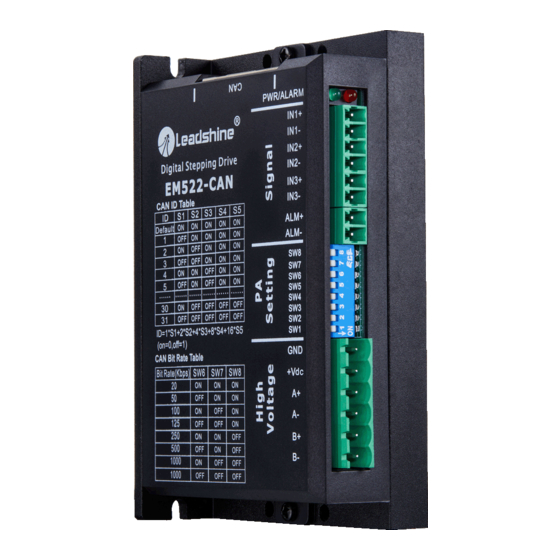
3. Connection Pin Assignment & DIP Switch & LED Indication The EM522-CAN has three connector blocks P1&P2&P3 (see above picture). P1 is for IO signals connections, P2 is for power and motor connections, and P3 is for CAN communication connection. The following tables are brief descriptions of the two connectors. -
Page 8: Connector P2
Motor Phase B connections. Connect motor B+ wire to B+ Pin; motor B- wire to B- Warning Warning: (1) Don’t plug or unplug the P2 terminal block to avoid drive damage or injury when EM522-CAN is powered on; (2) Don't connect the power supplier to motor connection terminal, and don't connect +VDC and GND inversely, otherwise, drive will be damaged. -
Page 9: Can Id Setup
EM522-CAN Field bus Stepper Drive User Manual V1.0 3.2.1 CAN ID Setup Low 5 bits of CAN ID are set by DIP switch SW1~SW5, and high 5 bits of CAN ID are set by controller, as shown in the following table. -
Page 10: Can Baud Rate Setup
EM522-CAN Field bus Stepper Drive User Manual V1.0 Notes: (1) SW1~SW5 set to "on" all will be invalid ID; (2) Should restart the power after modifying CAN ID. Notice 3.2.2 CAN Baud Rate Setup CAN baud rate can be set by DIP switch SW6~SW8, as shown below:... -
Page 11: Led Light Indication
There are two LED lights for DM56-CAN. The GREEN one is the power indicator which will be always on generally. The RED one is a protection indicator which will flash 1-2 times in a 3-second period, when protection enabled for a EM522-CAN. Different number of flashes indicates different protection type ,as shown following table. Time(s) of... -
Page 12: Terminal Resistance
4.2 Typical Connection EM522-CAN adopt CANopen protocol, typical schematic wiring topology structure as below: Controller&Control card Figure 2: The topology of the CAN network... -
Page 13: Motor Connection
12~24VDC ALM - Figure 3: The wiring diagram of each EM522-CAN Notes: (1) The EM522-CAN at the end of the network need to plug a terminal resistance in any one of the P3 Notice interface(RJ45); (2) In order to avoid bad insulation performance as heating, cable and wire should be fixed well and keep away from motors and drives. -
Page 14: Connections Of 6-Lead Motor
EM522-CAN Field bus Stepper Drive User Manual V1.0 4.3.2 Connections of 6-lead Motor Like 8 lead stepping motors, 6 lead motors have two configurations available for high speed or high torque operations. The higher speed configuration, or half coil, is described, because it uses one half of the motor’s inductor windings. The higher torque configuration, or full coil, uses the full coil windings. -
Page 15: Power Supply Selection
4.4.2 Power Supply Sharing Multiple EM522-CAN drives can share one power supply to reduce cost, if that power supply has enough power capacity. To avoid cross interference, connect each stepper drive directly to the shared power supply separately. To avoid cross interference, DO NOT daisy-chain connect the power supply input pins of the Drivers. -
Page 16: Object Dictionary Introduction
Object Dictionary is an organized group of objects, which maps the stepper drive related parameters and variables. Parameters of EM522-CAN can be configured via CAN to USB adaptor and Leadshine CANopen software or PLC & controller & control card, use SDO communication mode to modify the drive parameters. Corresponding ESD file and Leadshine CANopen software can be free download in Leashine official website: http://www.leadshine.com. - Page 17 EM522-CAN Field bus Stepper Drive User Manual V1.0 1:Motor running direction reverse Alarm detection selection: 1:Enable.0:Disable bit0: Over-current (error code:1, Alarm detection red LED flashes 1 time) selection (this parameter bit1:Over-voltage (error code:2, 2056+00 Enable R/W/S 0x03 0~0xffff red LED flashes 2 times)
- Page 18 EM522-CAN Field bus Stepper Drive User Manual V1.0 0: Motor normal standby when Motor power on 2073+00 auto-running when R/W/S 1: Motor turns 30°and reverse power on 30 when power on, then standby Slave station address: 2150+00 CAN ID high 2 bit...
-
Page 19: Model And Control
EM522-CAN Field bus Stepper Drive User Manual V1.0 bit0: Negative limit; bit1: Positive limit; Input port status 60FD+00 bit2: Home signal display bit3~bit15: Reserved; bit16: Emergency stop When IO output function switch to main station control, master controller can use the... - Page 20 Home position offset offset EM522-CAN can running under PP(position mode),PV(speed mode)and Homing(Back to the original point mode), 3 modes in total.(Specific protocol specification is in conformity with standard Canopen, specific operation can refer to 《DM-CAN series CANopen Technical instruction manual》)
- Page 21 EM522-CAN Field bus Stepper Drive User Manual V1.0...
-
Page 22: Parameters Configuration Via Leadshine Canopen Software
4.6.2 Connecting Leadshine CANopen software Before connecting the EM522-CAN to PC through a CAN to USB adapter, please ensure the right wiring refer to the following figure: (1) Connect with PC software... - Page 23 After setting the ①②③ step in the above picture, then clicking the button of ‘Connect’ Open another interface as following picture, please select the correct CAN ID setting by SW1~SW5, when showing the step ② character string, it means that the EM522-CAN connect with PC software successfully.
- Page 24 EM522-CAN Field bus Stepper Drive User Manual V1.0 (2) Parameters configuration Click the icon of , it will upload the default parameter as following picture. You also can import a configured file to cover the default parameter via clicking button①, after modifying the parameters, you need to click button ③...
- Page 25 EM522-CAN Field bus Stepper Drive User Manual V1.0 Key parameter: Address Name Detail 2000 Current peak Peak current output of the drive 2001 Motor resolution Microstep 2002 Standby time After this time that the output current of drive will be declined...
- Page 26 EM522-CAN Field bus Stepper Drive User Manual V1.0 As usual, the drive will auto-tuning the motor to output its optimal performance, but if you prefer to tuning the Kp and Ki of current loop through manual operation, please set the 2013H to ‘0’ and click the Click icon to open this window.
-
Page 27: Canopen Communication Overview
5. CANopen Communication Overview This chapter only briefly introduce frequently used concept and matters need attention when using EM522-CAN. In order to make the users can understand conventional method of DM-CAN series products in shortest time. If you need to know the DM - CAN series more detailed CANopen technical content, please refer to 《... -
Page 28: Explanation Of Nouns
PDO(TPDO) and receiving PDO (RPDO). Transmitting and receiving just relative to Leadshine CANopen drive (Such as the PDO which is transmitted from EM522-CAN is named TPDO), EM522-CAN can support 3 groups of TPDO and 3 groups of RPDO at present. -
Page 29: Service Data Object (Sdo)
EM522-CAN Field bus Stepper Drive User Manual V1.0 RPDO4 1603H TPDO4 1A03H Notes: (1) Recommend to reduce the quantity of using PDO unless it’s necessary, in order to reduce the network Notice load. (3)PDO property PDO need to configure multiple properties, including transport is synchronous or asynchronous, the length of prohibit time, they are configured by modify corresponding address of the following chart. -
Page 30: Homing Mode
5.2.4 Homing mode DM-CAN Series drives define various homing method according to the CANopen DS402 standard protocol. Because EM522-CAN is open loop stepper drive, supported 17~30 homing mode currently. Specific motion trail of various homing method is shown as below:... - Page 31 EM522-CAN Field bus Stepper Drive User Manual V1.0 21~22: 23~26: 27~30:...
- Page 32 EM522-CAN Field bus Stepper Drive User Manual V1.0 Initial position1 Initial position2 Initial position3 Figure9 No.17~30 homing method (1) Homing movement speed Homing movement speed contains high speed and low speed. Take the direction of the last track in homing movement as a reference, which with the same direction is low speed movement and opposite is high speed movement.
-
Page 33: Trouble Shooting
EM522-CAN Field bus Stepper Drive User Manual V1.0 Under No.28 homing mode, the sliding block will slow down to 0, then turn left to stop immediately when meeting home switch again. Under No.29/30 homing mode, the sliding block will move left until leaving the home switch ... - Page 34 EM522-CAN Field bus Stepper Drive User Manual V1.0 acceleration Motor torque is too small Choose high torque motor Power supply voltage or output current setting is too Appropriately increase voltage or current small Refer to the manual of master station alarm and processing.
-
Page 35: Warranty
Twelve Month Warranty Leadshine Technology Co., Ltd. warrants its products against defects in materials and workmanship for a period of 12 months from shipment out of factory. During the warranty period, Leadshine will either, at its option, repair or replace products which proved to be defective. -
Page 36: Contact Us
EM522-CAN Field bus Stepper Drive User Manual V1.0 8. Contact Us China Headquarters Address: Floor 11, Block A3, Nanshan iPark, Xueyuan Avenue 1001, Shenzhen, Guangdong, 518055, China Web: http://www.leadshine.com Sales Hot Line: Tel: 86-755-2643 4369 (for All) 86-755-2641-7674 (for Asia, Australia, Africa areas)
Need help?
Do you have a question about the EM522-CAN and is the answer not in the manual?
Questions and answers