Table of Contents
Advertisement
Quick Links
The content in this manual has been carefully prepared and is believed to be accurate,
but no responsibility is assumed for inaccuracies.
User's Manual
Leadshine reserves the right to make changes without further notice to any products
For
herein to improve reliability, function or design. Leadshine does not assume any
DCS810V2
liability arising out of the application or use of any product or circuit described
herein; neither does it convey any license under its patent rights of others.
Leadshine's general policy does not recommend the use of its products in life
Digital DC Servo Driver
support or aircraft applications wherein a failure or malfunction of the product may
Revision 1.0
directly threaten life or injury. According to Leadshine's terms and conditions of
©2009 All Rights Reserved
sales, the user of Leadshine's products in life support or aircraft applications
assumes all risks of such use and indemnifies Leadshine against all damages.
Attention: Please read this manual carefully before using the driver!
©2009 by Leadshine Technology Company Limited.
3/F, Block 2, Nanyou Tianan Industrial Park, Nanshan Dist, Shenzhen, China
All Rights Reserved
Tel: (86)755-26434369
Fax: (86)755-26402718
URL:
www.leadshine.com
E-Mail:
sales@leadshine.com
Advertisement
Table of Contents

Subscribe to Our Youtube Channel
Related Manuals for Leadshine Technology DCS810V2


Summary of Contents for Leadshine Technology DCS810V2
- Page 1 Leadshine against all damages. Attention: Please read this manual carefully before using the driver! ©2009 by Leadshine Technology Company Limited. 3/F, Block 2, Nanyou Tianan Industrial Park, Nanshan Dist, Shenzhen, China All Rights Reserved...
-
Page 2: Table Of Contents
Contents Contents Cable Routing ................... 12 Table of Contents Twisted Wires.................... 12 Cable Shielding ..................13 1. Introduction, Features and Applications..............1 System Grounding..................13 Introduction ......................1 Power Supply Connection................. 13 Features ........................ 1 5. Tuning the servo....................14 Applications ...................... -
Page 3: Introduction, Features And Applications
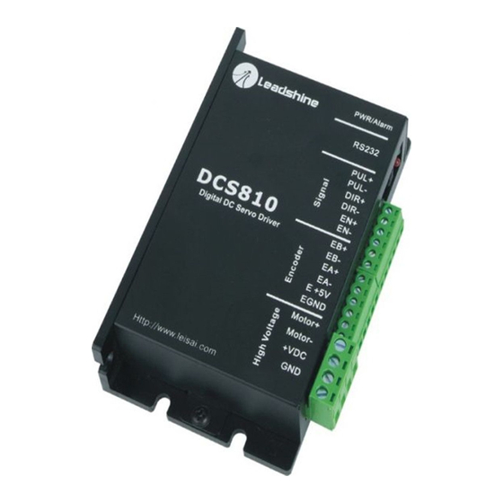
Introduction Encoder Error Protection................46 Position Following Error Protection............46 The DCS810V2 is a digital DC servo driver developed with DSP and high efficient Protection Indications................47 MOSFET technologies. In position control, it’s easy for the end users to change Changing Default Motor Direction .............. -
Page 4: Applications
It performs better in equipments desired working temperature should be <80℃(176℉); for low noise, high velocity, high precision and high reliability. It is recommended to mount the driver vertically to maximize heat sink area. Electrical Specifications (T = 25℃/77℉) DCS810V2 Parameters Min. Typical Max. Unit... -
Page 5: Operating Environment And Parameters
Operating Environment and Parameters Power Connector Signal Description Natural cooling or forced cooling Cooling Motor+ Motor positive connection. Avoid dust, oil fog and corrosive gases Motor- Motor negative connection. Environment +VDC +18 TO 80VDC power input. 0℃-50℃ (32℉-122℉) Ambient Temperature Operating Environment Power ground. -
Page 6: Pul/Dir And Cw/Ccw Mode Settings
Control Signal Connections The DCS810V2 can accept differential and single-ended inputs (including open-collector and PNP output). The DCS810V2 has 2 optically isolated logic inputs Figure 4: Connections to PNP signal (common-cathode) to accept line driver control signals. These inputs are isolated to minimize or eliminate electrical noises coupled onto the control signals. -
Page 7: Encoder Connections
Figure 3-4 or Figure 3-5. If the encoder drains more than Two typical connections of the DCS810V2 are shown as Figure 3-9 and Figure 3-10. 50mA, use an external DC supply and connect it as Figure 3-6 or Figure 3-7. -
Page 8: Servo Setup
Prepare Controller power wires at least 5 cm. Prepare a controller with pulse and direction signals. However, the DCS810V2 has a built-in motion controller for self-test and Servo Tuning. The built-in motion controller can generate control signal with trapezoidal velocity profile. -
Page 9: System Connections And Noise Prevention
The combination of twisted pair wires and a differential signal the DCS810V2 driver. The distance between the DC power supply of the drive and significantly adds to noise immunity. Power wires should be twisted as a group Tel: (86)755-26434369 Website: www.leadshine.com... -
Page 10: Tuning The Servo
If the red LED is off and the motor is normal, then you can start to tune the servo As mentioned in previous contents, the DCS810V2 is a digital servo driver and its with selected tool. ProTuner, and STU are available for the DCS810V2. -
Page 11: Pc Window Based Tuning Using Protuner
The ProTuner is windows based setup software for tuning Leadshine’s digital drivers. It can run in windows systems, including Win95/Win98/WindowsNT/ Windows Tuning servo systems formed by DCS810V2 drivers can be summarized as the 2000/Windows XP. And the selected PC should have 1 serial port at least for following rules: communicating with the driver. - Page 12 Figure 6-3: User’s information settings Figure 6-1: Begin to install the ProTuner Figure 6-2: License agreement Figure 6-4: Installation folder settings Choose “I agree to the terms of this license agreement” and click Next to continue installation. The user can enter user’s information in the following window. See Figure 6-3.
-
Page 13: Rs232 Interface Connection
Figure 6-5: Shortcut folder setting Figure 6-7: Installing the ProTuner Set the “Shortcut Folder” in Figure 6-5 and continue to install the ProTuner by following Figure 6-6 and Figure 6-7. An Installation Successful window will appear if the ProTuner is installed successfully. See Figure 6-8. Figure 6-8: Finish installation Note: Leadshine also offers special version ProTuner which does not need installation. -
Page 14: Testing The Servo
You may wish to secure the motor so it can’t jump off the bench. Turn on the power supply, the green (Power) LED will light. The DCS810V2 has default parameters stored in the driver. If the system has no hardware and wirings problem, the motor should be locked and the driver should be ready. -
Page 15: Com Config Window
Com Config Window Kp: Current Proportional gain. Increase this parameter to make current rise fast. Figure 6-11: RS232 communication configuration window Ki: Current Integral gain. Adjust this parameter to reduce the steady error. Serial Port: Select the serial communication port to which the driver is connected. I-test: The current amplitude for the step response. - Page 16 Gear Ratio, Position Following Error Limit, etc. tuning, and will not affect the driver to interpret the encoder feedback signal. With regard to the DCS810V2, feedback resolution is ×4 encoder line count. Kp: Position Proportional Gain. Proportional Gain determines the response of the system to position errors.
- Page 17 velocity profile, and Interval, Repeat Times of self motion test. Error (v_err), Position Following Error (p_err), Current Feedback (i_bak), Velocity Feedback (v_bak), Position Feedback (p_bak), Current Command V_top: Maximum Speed. The maximum speed of trapezoidal velocity profile. Its (i_ref), Velocity Command (v_ref), Position Command (p_ref). unit is RPM.
-
Page 18: Digital_Monitor
Digital_monitor Digital Monitor: Displays curves and dynamic values of different point of different curves. Figure 6-16: Error check window OverCurrent: Over-current Protection. Protection will be activated when Figure 6-15: Digital scope window continuous current exceeds 20A. I: Current. Displays dynamic values for Current related curve(s). Dynamic value OverVoltage: Over-voltage Protection. -
Page 19: About
Feed-forward gain can be added to improve tracking performance (i.e. minimize the difference between commanded and actual position). The velocity loop is disabled in current version DCS810V2, and it adopts Position around Current (Torque) mode. Position around Torque: This mode is most common in point-to-point applications, where actual motion between start and end point is not very critical. -
Page 20: Current Loop Tuning Example
When tuning position around the current loop, a high derivative gain may be necessary on top of both proportional and integral gains. For most of the DCS810V2 drivers have been being sold to the customers with Leadshine’s DCM5xxxx DC servo motors, Leadshine will tune the current loop before sending drivers out of the factory. - Page 21 Step 2: Click the Start button and the plot window will show two curves. The red Kp and back off. Our purpose is to make the green curve (the actual current) a little one is target current and the green one is actual current. There is large gap between higher than the red curve (the target).
-
Page 22: Velocity And Position Loop Tuning
Velocity and Position Loop Tuning Before trying to manage the velocity and position loop parameters (Vp, Vi, Kp, Kp, Kaff, see page 25), connect the system as figure 6-19. Then set self-test motion parameter and select the display curve in digital scope as figure 6-25, figure 26. TraceTime affects the display length of the curve. - Page 23 Step 2: Increase Vp until motor noise/vibration begins. Then back off. To activate Our purpose is to get the highest system stiffness but lowest motor noise. However, sometimes we need to trade off between them because high loop gain leads to big the noise/vibration, sometimes you need to give a disturbance to the load by either overshoot even vibration.
- Page 24 Step 3: Increase Kp to maximize the system stiffness until motor noise/vibration begins, following the same way as Vp. See figure 6-29, 6-30, 6-31 and 6-32. The motor shaft or load is stiff enough at standstill when we increase Kp to 1800 and the motor noise/vibration can be accepted.
-
Page 25: Using Tips
To improve reliability, the driver incorporates some built-in protection functions. can meet your application requirements, then the easier tuning way the better. Just The DCS810V2 uses one RED LED to indicate what protection has been activated. like if the performances of the products can meet your application requirements, then The periodic time of RED is 5 s (seconds), and how many times the RED turns on the cheaper the better. -
Page 26: Phase Error Protection
Changing Default Motor Direction this protection if the motor power lines are not connected. The DCS810V2 will turn the motor in the CW direction when the direction input is Encoder Error Protection “high” (logical “1”). If instead CCW is preferred, then: 1) Reverse the “motor +”... - Page 27 Maximum Pulse Input Frequency Load data from file to Drive Maximum Pulse Input Frequency is the highest frequency that the driver can accept. When communication between the ProTuner and the ACS806 is established, you To convert this frequency to RPM, use the following formula: can open a configuration file then download the data from the file to the drive.
- Page 28 Send failed product to distributor in to be defective. your area or: Leadshine Technology Co., Ltd. Floor 3, Block 2, Tianan Industrial Park, Nanshan Dist, Shenzhen, China. Also enclose information regarding the EXCLUSIONS circumstances prior to product failure.
- Page 29 Contact Us China Headquarters Address: 3/F, Block 2, Nanyou Tianan Industrial Park, Nanshan District Shenzhen, China Web: http://www.leadshine.com Sales Hot Line: Tel: 86-755-2643 4369 (for All) 86-755-2641-7674 (for Asia, Australia, Africa areas) 86-755-2640-9254 (for Europe, America areas) Fax: 86-755-2640-2718 Email: sales@leadshine.com. Technical Support: Tel: 86 755-2641-8447 and 86-755-2647-1129 Fax: 86-755-2640-2718...
Need help?
Do you have a question about the DCS810V2 and is the answer not in the manual?
Questions and answers