
Related Manuals for SeaLevel VERSA COMM+4


Summary of Contents for SeaLevel VERSA COMM+4
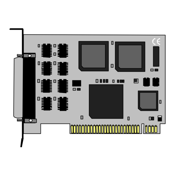
- Page 1 ™ VERSA COMM+4 USER’S MANUAL Part Number 3410 Sealevel Systems, Inc Phone: (864) 843-4343 155 Technology Place Fax: (864) 843-3067 P.O. Box 830 www.sealevel.com Liberty, SC 29657...
-
Page 2: Table Of Contents
Contents ................ 1 NTRODUCTION ................... 1 VERVIEW ’ ................1 NCLUDED ............. 1 ACTORY EFAULT ETTINGS ................2 ETUP ................2 DDRESS ELECTION ..............3 NABLE ISABLE IRQ S ................... 3 ELECTION ..............4 NTERRUPT PTIONS ................6 NSTALLATION ............ 6 PERATING YSTEM NSTALLATION... - Page 3 Figure 6 - Header E5, Sharing IRQ’s with another adapter......5 Figure 7 - IRQ Headers E1 - E5 (Factory Default).........5 Figure 8 - Connector Pin Assignments.............8 Figure 9 - Asynchronous Communications Bit Diagram.......14 ©1996d Sealevel Systems, Incorporated. All rights reserved.
-
Page 5: Introduction
RS-232 electrical interface, such as modems, data-entry terminals, and plotters. What’s Included The VERSA COMM+4 is shipped with the following items. If any of these items are missing or damaged, contact the supplier. •... -
Page 6: Card Setup
Card Setup Card Setup The VERSA COMM+4 contains several jumper straps which must be set for proper operation. Address Selection Each port on the VERSA COMM+4 occupies 8 consecutive I/O locations. A DIP-switch is used to set the base address for these locations. Be careful when selecting the base address as some selections conflict with existing ports. -
Page 7: Port Enable / Disable
Card Setup Port Enable / Disable Each port on the VERSA COMM+4 can be enabled or disabled with switch position 8 on the DIP-switch. The port is enabled with the switch "On" or "Closed" and disabled when "Off" or "Open". If any port is disabled, be sure to disable the interrupt request for that port by removing the IRQ jumper. -
Page 8: Interrupt Mode Options
IRQs possible. If you are using more than one VERSA COMM+4 or a compatible card in a bus you should only have one port set to " M". The following example shows all four ports sharing a single IRQ. -
Page 9: Figure 6 - Header E5, Sharing Irq's With Another Adapter
Card Setup Set jumper to " S" if you are using more than one VERSA COMM+4 in a bus or you wish to completely remove the pull-down resistor for hardware compatibility. Setting the board in this configuration when it is not accompanied by a pull-down resistor will prevent the ports from triggering an interrupt.. -
Page 10: Installation
Installation Installation The VERSA COMM+4 can be installed in any of the PC expansion slots, but to access the “AT” or (E)ISA IRQ’s (10, 11, 12, 15) it must be installed in one of the 16 bit slots. The VERSA COMM+4 contains several jumper straps for each port which must be set for proper operation prior to installing the card into the computer. -
Page 11: Technical Description
Technical Description Technical Description The Sealevel VERSA COMM+4 provides 4 additional serial ports for terminals, modems, printers, etc. The VERSA COMM+4 can be configured as COM1: through COM4:, or as any other I/O address (up to 3FF HEX), providing total compatibility with most communications software and languages. -
Page 12: Connector Pin Assignments
The most common way to do this is connect RTS to CTS and RI. Also, connect DCD to DTR and DSR. Terminating these pins, if not used, will help insure you get the best performance from your adapter. Sealevel Systems VERSA COMM+4 Page 8... -
Page 13: Specifications
IPC 610-A Class-III standards are adhered to with a 0.1 visual A.Q.L. and 100% Functional Testing. • All Sealevel Systems Printed Circuit boards are built to U.L. 94V0 rating and are 100% electrically tested. These printed circuit boards are solder mask over bare copper or solder mask over tin nickel. -
Page 14: Appendixa - Troubleshooting
No two adapters can occupy the same I/O address. 3. Make sure the Sealevel Systems adapter is using a unique IRQ. While the Sealevel Systems adapter does allow the sharing of IRQ’s, many other adapters (i.e. SCSI adapters & on-board serial ports) do not. The IRQ is typically selected via an on-board header block. - Page 15 2E8-2EF is typically reserved for COM4: 7. Please refer to your included diskette for any post production manual updates and application specific information. 8. Always use the Sealevel Systems diagnostic software when Troubleshooting a problem. This will eliminate the software issue from the equation.
-
Page 16: Appendixb - How T O Get Assistance
3. Sealevel Systems maintains a forum on CompuServe providing utilities and new product information. This forum is accessed by typing “GO Sealevel” at the command prompt. 4. Technical support is available Monday to Friday from 8:00 a.m. -
Page 17: Appendixc - Electrical Interface
(space) and -12 volts (-3 to -10 volts) denotes a binary 1 (mark). The RS-232 and the EIA/TIA-574 specification define two types of interface circuits Data Terminal Equipment (DTE) and Data Circuit-Terminating Equipment (DCE). The Sealevel Systems Adapter is a DTE interface. Sealevel Systems VERSA COMM+4 Page 13... -
Page 18: Appendixd - Asynchronous Communications
The communication parameters are baud rate, parity, number of data bits per character, and stop bits (i.e. 9600,N,8,1). Sealevel Systems VERSA COMM+4 Page 14... -
Page 19: Appendixe - Silk -Screen
Appendix E - Silk-Screen Appendix E - Silk-Screen 4.2" 8.6" 3.9" Sealevel Systems VERSA COMM+4 Page 15... -
Page 20: Appendixf - Schematic
Appendix F - Schematic Appendix F - Schematic Sealevel Systems VERSA COMM+4 Page 16... - Page 21 Appendix F - Schematic Sealevel Systems VERSA COMM+4 Page 17...
-
Page 22: Appendixg - Compliance Notices
Always use cabling provided with this product if possible. If no cable is provided or if an alternate cable is required, use high quality shielded cabling to maintain compliance with FCC/EMC directives. Sealevel Systems VERSA COMM+4 Page 18... -
Page 23: Warranty
Should this product fail to be in good working order at any time during this period, Sealevel Systems will, at it's option, replace or repair it at no additional charge except as set forth in the following terms. This warranty does not apply to products damaged by misuse, modifications, accident or disaster.
Need help?
Do you have a question about the VERSA COMM+4 and is the answer not in the manual?
Questions and answers