
Related Manuals for SeaLevel eI/O Series


Summary of Contents for SeaLevel eI/O Series
- Page 1 Modules User Manual | eI/O © Sealevel Systems, Inc. eI/O Manual | SL9221 01/2023...
-
Page 2: Table Of Contents
HARDWARE CONFIGURATION .......................... 31 MOUNTING OPTIONS ............................39 APPENDIX A – HANDLING INSTRUCTIONS ....................40 APPENDIX B– HOW TO GET ASSISTANCE ...................... 41 APPENDIX C – COMPLIANCE NOTICES ......................42 WARRANTY ................................ 42 © Sealevel Systems, Inc. eI/O Manual | SL9221 01/2023... -
Page 3: Before You Get Started
Note The lowest level of importance used to provide background information, additional tips, or other non-critical facts that will not affect the use of the product. © Sealevel Systems, Inc. eI/O Manual | SL9221 01/2023... -
Page 4: Introduction
I/O configurations. Each eI/O model is designed for maximum flexibility and easy field wiring. For easy software integration, application programs or 3 rd party software can use the Sealevel SeaMAX TM library or industry standard Modbus TCP (Ethernet) protocol. - Page 5 140PoE – 4 Form A Reed Relay Outputs eI/O 150PoE – 4 Form C Relay Outputs eI/O 160PoE – 32 Channel TTL Interface eI/O 170PoE – 8 Analog Inputs/2 Optically Isolated Inputs/2 Solid State Relay Outputs © Sealevel Systems, Inc. eI/O Manual | SL9221 01/2023...
- Page 6 Optional Items Depending on the interface type, your eI/O module may include additional accessories. Included accessories are listed below. All items can be purchased from our website (www.sealevel.com) by calling our sales team at (864) 843-4343. POWER OVER ETHERNET SERIES...
- Page 7 240VAC to 12VDC @ 500mA Wall Mount Power Supply (Part# TR106) The TR106 is a wall wart style power supply for the United Kingdom, Hong Kong, Singapore, and Malaysia. The TR106 is rated for 240VAC input and 12VDC output at 500mA. © Sealevel Systems, Inc. eI/O Manual | SL9221 01/2023...
- Page 8 Standard 7' CAT5 UTP Patch Cable (RJ45). CAT5 Patch Cable, 10' in Length (Part# CA247) 10’ Blue Ethernet Patch Cable. Can be used to connect eI/O Ethernet modules to a hub or switch. © Sealevel Systems, Inc. eI/O Manual | SL9221 01/2023...
-
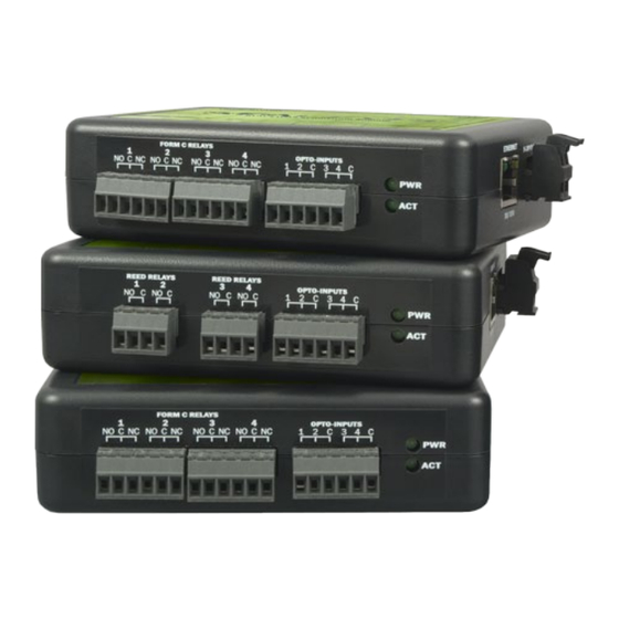
Page 9: Ei/O Hardware Description
9-30 VDC 5W MAX power input • (600mA MAX @ 9V; 420mA MAX @12V; 210mA MAX @ 24V) • 802.3af-2003 Power over Ethernet © Sealevel Systems, Inc. eI/O Manual | SL9221 01/2023... - Page 10 Status LEDs are also included on the front of all eI/O modules to indicate the following information: Power (Green) – Lights when power is applied to the module. • Act (Green) – Light blinks when Modbus/TCP activity is present or when new firmware is • being downloaded. © Sealevel Systems, Inc. eI/O Manual | SL9221 01/2023...
- Page 11 Relay Max Operate Time, including Bounce* Relay Max Release Time* 0.2ms Do not connect protective earthing or protective bonding conductor wiring of any equipment to relay contact outputs. *Minimum hardware requirements © Sealevel Systems, Inc. eI/O Manual | SL9221 01/2023...
- Page 12 ≤30 VDC @ 5A max. >30 VDC @ 2000mA max. (100mA min.) Contact Current (AC) 6A max. Do not connect protective earthing or protective bonding conductor wiring of any equipment to relay contact outputs. © Sealevel Systems, Inc. eI/O Manual | SL9221 01/2023...
- Page 13 Each pair of inputs shares a common and field wiring is simplified via 3.5mm field removable terminal blocks. Inputs Type 4 non-polarized optically isolated inputs Voltage Range 5-30VDC non-polarized Isolation 2500VAC RMS / 3500VDC Input Resistance 6.2K Ohms in series © Sealevel Systems, Inc. eI/O Manual | SL9221 01/2023...
- Page 14 Relay Max Operate Time, including Bounce* Relay Max Release Time* 0.2ms Do not connect protective earthing or protective bonding conductor wiring of any equipment to relay contact outputs. *Minimum hardware requirements © Sealevel Systems, Inc. eI/O Manual | SL9221 01/2023...
- Page 15 ≤30 VDC @ 5A max. >30 VDC @ 2000mA max. (100mA min.) Contact Current (AC) 6A max. Do not connect protective earthing or protective bonding conductor wiring of any equipment to relay contact outputs. © Sealevel Systems, Inc. eI/O Manual | SL9221 01/2023...
- Page 16 IDC ribbon cable to connect an industry standard relay rack for PC based control and automation of equipment including sensors, switches, security control systems, and other industrial automation systems. The eI/O-160 50 pin digital interface is pin compatible with the Sealevel SeaDAC Lite 8126 and will accept 8126 accessories.
- Page 17 Each bit is pulled to +5V through a 10K Ω pull-up resistor to insure each bit is at a known state when not driven. If an input is not connected to ground, it will read as a one (1) due to the 10K Ω pull-up resistors on each port. © Sealevel Systems, Inc. eI/O Manual | SL9221 01/2023...
- Page 18 © Sealevel Systems, Inc. eI/O Manual | SL9221 01/2023...
- Page 19 0V-5V, 0V-10V, -5V-5V, -10V-10V Resolution 12bit Input Impedance 100kΩ The analog inputs can operate as 8 single ended inputs or 4 differential inputs. See wiring diagrams below for terminal numbering and channel pairing. © Sealevel Systems, Inc. eI/O Manual | SL9221 01/2023...
- Page 20 The optically isolated digital inputs featured on the 170 are designed unlike the opto-inputs found on many other Sealevel products. The 170 provides a voltage to the opto input, which is current limited with a 330 ohm resistor. Connecting either of the inputs to a common pin will cause current to flow through the opto- isolator, activating the input.
-
Page 21: Power Options
9-30VDC source using the screw terminals on the side of the unit. Sealevel offers several power supply choices to make connection easy (see the Optional Items section in the beginning of this document). -
Page 22: Seamax Application Suite
API documentation and code samples are automatically installed with the SeaMAX Suite and can be found in Windows by clicking Start All Programs Sealevel Systems SeaMAX Documentation. For convenience, Sealevel offers a PDF version of the SeaMAX manual on our website. - Page 23 Software drivers are also available on the product webpage. To install Sealevel Systems software, you must log in as an administrator or have administrator privileges in Windows. Only users running Windows 7 or newer should utilize these instructions for accessing and installing the appropriate driver via Sealevel’s website.
- Page 24 Windows 2000, XP, Vista, and Windows 7. HOST PC CONFIGURATION TAB When you run the MaxSSD utility (Start All Programs Sealevel Systems SeaMAX MaxSSD Configuration Utility) it will default to the “Host PC Configuration” tab. This tab allows the user to choose the initial communication settings for the connected I/O device.
- Page 25 Click the “Get SeaIO Module Settings” button. After a short delay, the information for that I/O module should be displayed. If no information appears, verify that the host settings are correct and make changes if necessary. © Sealevel Systems, Inc. eI/O Manual | SL9221 01/2023...
- Page 26 After a successful Get operation, additional tabs may be displayed in MaxSSD, depending on the device model found. These tabs display device I/O and allow easy configurations for all SeaMAX supported devices. © Sealevel Systems, Inc. eI/O Manual | SL9221 01/2023...
- Page 27 DIGITAL I/O TAB The ‘Digital IO’ tab of MaxSSD is displayed when using Sealevel I/O devices featuring discrete inputs and outputs. It displays the device’s current input and/or output status in an intuitive and usable manner. When banks of inputs are displayed, the status LEDs update on each of the banks automatically. This allows you to actively monitor external signals.
- Page 28 A/D INPUTS TAB The “A/D Inputs” tab displays the current state of the analog-to-digital channels for Sealevel I/O devices that feature A/D inputs. Settings are provided for both device wide and per-channel configuration. The “Device Configuration” selection drop-box adjusts the arrangement and function of the A/D input channels.
- Page 29 6. If these steps do not solve your problem, please contact Sealevel Technical Support. Our technical support is free and available from 8:00 AM – 5:00 PM EST, Monday through Friday.
- Page 30 5. Release the button. If these steps do not solve your problem, please call Sealevel Systems’ Technical Support, (864) 843-4343. Our technical support is free and available from 8:00 A.M.- 5:00 P.M. Eastern Time Monday through Friday.
-
Page 31: Hardware Configuration
IP address of the network adaptor to which your eI/O module is connected. The IP address of the adaptor should be 192.168.42.254 (the last octet can be anything but 253). Start the Ethernet Config utility (Start All Programs Sealevel Systems SeaMAX Ethernet Configuration Tool) installed with SeaMAX. - Page 32 DHCP server. Once it receives an IP address, the status LEDs will remain on. Now start MaxSSD (Start All Programs Sealevel Systems SeaMAX MaxSSD Configuration Utility) and choose the correct IP address to communicate with the eI/O module. Ensure a successful Get operation (refer to the MaxSSD section of this manual for more information).
- Page 33 Contact your network administrator if you are unsure of the proper network settings to choose. If a DHCP server is available, select the “Enable DHCP Configuration” checkbox. Otherwise, complete the network settings and click the “Recover Module” button to complete the configuration changes. © Sealevel Systems, Inc. eI/O Manual | SL9221 01/2023...
- Page 34 In the event that a newer version of the firmware is available, it is possible to upgrade the firmware in the unit. This can be done through the same port that is used to do normal communications with the unit. The unit must be directly connected to the programming computer. © Sealevel Systems, Inc. eI/O Manual | SL9221 01/2023...
- Page 35 Once the firmware has been erased, you must either be able to re-program it locally or send it back to Sealevel Systems, Inc. for reprogramming. Exercise caution when performing a firmware upgrade to ensure that the process does not get interrupted until it is completed.
- Page 36 The unit will then reboot itself to reload the new firmware. At this point, the ACT light will turn off, and the terminal window will close. MaxSSD will return you to the Host PC Configuration tab. © Sealevel Systems, Inc. eI/O Manual | SL9221 01/2023...
- Page 37 Once you are at the command prompt, browse to your SeaMAX folder. The default location is “C:\Program Files\Sealevel Systems\SeaMAX\” (or “C:\Program Files (x86)\Sealevel Systems\SeaMAX” on 64-bit systems). Your *.hex file should be saved to this folder as well. If your...
- Page 38 ETHERNET / POE (CONNECTOR – RJ-45) Signal PoE Mode A PoE Mode B TX+/DC+ TX-/DC+ RX+/DC- RX-/DC- This module is not intended to be directly connected to wiring outside a building. © Sealevel Systems, Inc. eI/O Manual | SL9221 01/2023...
-
Page 39: Mounting Options
The units ship with four rubber feet that help prevent the devices from sliding due to vibration and help protect surfaces from scratches. The small enclosures take up very little space. © Sealevel Systems, Inc. eI/O Manual | SL9221 01/2023... -
Page 40: Appendix A - Handling Instructions
Keep work area free of non-conductive materials such as ordinary plastic assembly aids • and Styrofoam. Use field service tools such as cutters, screwdrivers, and vacuum cleaners which are • conductive. Always place drives and boards PCB-assembly-side down on the foam. • © Sealevel Systems, Inc. eI/O Manual | SL9221 01/2023... -
Page 41: Appendix B- How To Get Assistance
When calling for technical assistance, please have your user manual and current adapter settings. If possible, please have the adapter installed in a computer ready to run diagnostics. Sealevel Systems provides an FAQ section on its web site. Please refer to this to answer many common questions. This section can be found at http://www.sealevel.com/faq.asp. -
Page 42: Appendix C - Compliance Notices
Always use cabling provided with this product if possible. If no cable is provided or if an alternate cable is required, use high quality shielded cabling to maintain compliance with FCC/EMC directives. Warranty © Sealevel Systems, Inc. eI/O Manual | SL9221 01/2023... - Page 43 Sealevel's commitment to providing the best I/O solutions is reflected in the Lifetime Warranty that is standard on all Sealevel manufactured I/O products. We are able to offer this warranty due to our control of manufacturing quality and the historically high reliability of our products in the field. Sealevel products are designed and manufactured at its Liberty, South Carolina facility, allowing direct control over product development, production, burn-in and testing.
Need help?
Do you have a question about the eI/O Series and is the answer not in the manual?
Questions and answers