
Related Manuals for HEIDENHAIN ND 221B


Summary of Contents for HEIDENHAIN ND 221B
- Page 1 SALES & SERVICE: A Tech Authority, Inc. 13745 Stockton Ave. Chino CA 91710 909-614-4522 sales@atechauthority.com User’s Manual ND 221B Measured Value Displays English (en) 12/ 2001...
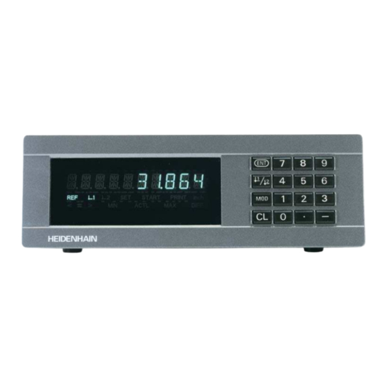
- Page 2 Display of actual value and input Numeric keypad (9 decades with algebraic sign) with decimal point SET START PRINT inch < > ACTL DIFF – HEIDENHAIN Status display with indicators...
- Page 3 Function Indicator Meaning • Set datum If the decimal point is also blinking: • Transfer input value Display is waiting for reference mark • Set display to value from P79 (P80!) traversing. • Leave parameter list If decimal point is not blinking: Reference mark has been traversed—...
- Page 4 Power cord 3 m (9.9 ft) User's Manual ND 221 B Adhesive plug-in feet For stacking ND 221B units This manual is for the ND 221 B measured value display with the following software number or higher: 349 797-04 The software number is indicated on a label on...
-
Page 5: Table Of Contents
Contents Working with the ND Display Units Installation and Specifications Position Encoders and Reference Marks Rear Panel, Accessories Switch-On, Traversing Reference Marks Mounting Datum Setting Power Connection Measured Value Output Operating Parameters List of Operating Parameters Error Messages Linear Encoders Nonlinear Axis Error Compensation Locking the Keypad Displaying the Software Version... -
Page 6: Position Encoders And Reference Marks
Position Encoders and Reference Marks The ND 221 B display unit is designed for use with photoelectrical linear encoders with 11 µA sinusoidal signals: primarily for HEIDENHAIN MT length gauges with 11 µA Scale in Distance-coded linear encoder reference marks The MT length gauges have one reference mark. -
Page 7: Switch-On, Traversing Reference Marks
Switch-On, Traversing the Reference Marks REF Mode ä Crossing over the reference marks automatically switches Turn on the power. the display to REF mode: The last assignment of display (Switch located on rear panel.) values to length gauge positions is stored in nonvolatile •... -
Page 8: Datum Setting
Datum Setting The datum setting procedure assigns a display value to a known position. With the ND 200 series, you can set two separate datum points. There are several ways to set the datum: • Enter a numerical value, or •... -
Page 9: Measured Value Output
ACTL DIFF – Measured values can be output over the RS-232-C/V.24 HEIDENHAIN interface (X31), for example to a printer or PC. There are several ways to start measured value output: ä Press the MOD key (check the parameter settings for P86). -
Page 10: Error Messages
Error Messages Display Effect/Cause Display Effect/Cause RS232 FAST Command for measured value Error during reception of parameter REC. PARAM. output followed too quickly by and compensation value lists another. Other error displays Encoder signal is too weak. SIGNAL If “OVERFLOW” appears, the measured value is too large or The scale may be contaminated. -
Page 11: Rear Panel, Accessories
Encoder input X1 HEIDENHAIN flange socket 9-pin Input signals 11 µA Maximum encoder cable length 30 m (98.5 ft) Input X1 for one HEIDENHAIN Ground connection Power 11 µA linear encoder Maximum input frequency 100 kHz switch RS-232-C/V.24 data interface (X31) -
Page 12: Mounting
Mounting 172 ± 0.2 6.77 ± .008" You can fasten the ND 221 B from below by using M4 screws (see illustration at right). Hole positions for mounting the ND display unit ND 221 B display units are stackable. Adhesive plug-in feet (supplied with your unit) prevent the stacked units from being moved out of place. -
Page 13: Power Connection
Power Connection The rear panel of the ND 221 B contains a connecting jack for a power cord with Euro connector (power cord supplied with the delivery). Minimum cross section of the power cord: 0.75 mm Power supply: 100 Vac to 240 Vac (–15% to +10%) 50 Hz to 60 Hz (±... -
Page 14: Operating Parameters
Operating Parameters To access a user parameter ..after switching on the display: Operating parameters allow you to modify the operating characteristics of your ND display unit and define the While ENT ... CL is evaluation of the encoder signals. Display first user parameter. - Page 15 Code number for changing protected operating Functions for changing the operating parameters parameters Function Page forward If you wish to change protected operating parameters, you in the list of operating parameters must first enter the code number 95 148: ä Select the user parameter P00 CODE.
-
Page 16: List Of Operating Parameters
List of Operating Parameters Parameter Settings / Function Parameter Settings/ Function Signal period of encoder P00 CODE Enter a code number: P31 S. PER. 9 51 48: To change the protected 0.000 000 01 < P31 < 99 999.9999 µm Default setting: 10 µm operating parameters 10 52 96: Nonlinear axis error compensation... - Page 17 500 SP Displayed measuring length ..... L = 620.000 mm Distance-coded with 1000 • SP Actual length (measured, e.g. (e.g. for HEIDENHAIN LS ...C) 1000 SP with the VM 101 comparator system from HEIDENHAIN) ....L = 619.877 mm Distance-coded with 2000 • SP 2000 SP Length difference ......
- Page 18 Parameter Settings / Function Parameter Settings / Function Additional blank lines Conversational language P51 RS232 P98 LANGUA. during data output BK LINE 1 German LANGUAGE DE £ £ÿ English LANGUAGE EN Default setting: 1 French LANGUAGE FR Italian LANGUAGE IT Value for datum point P79 PRESET Dutch...
-
Page 19: Linear Encoders
Linear Encoders The ND 221 B display unit is designed for use together with photoelectrical encoders with sinusoidal signals—11 µA Display step with linear encoders You can select a specific display step by adapting the following operating parameters: • Signal period (P31) •... - Page 20 Recommended parameter settings for HEIDENHAIN linear encoders with 11 µA signals Model Reference Millimeters Inches marks Display Display step step in mm in inches P 31 P 43 P 33 P 38 P 33 P 38 Single 0.0005 0.00002 MT xx01 0.0002...
- Page 21 Recommd. parameter settings for HEIDENHAIN linear encoders with 11 µA signals (continued) Model Reference Millimeters Inches marks Display Display step step in mm in inches P 31 P 43 P 33 P 38 P 33 P 38 LS 106/106C Single/1000 0.001...
-
Page 22: Nonlinear Axis Error Compensation
Spacing = 2 [µm]. usually measured with a comparator measuring system (such Enter the value of the exponent x in into the compensation as the HEIDENHAIN VM 101). value table. Minimum input value: 6 (= 0.064 mm) You select the compensation table through P00 CODE and by Maximum input value: 20 (= 1048.576 mm) - Page 23 Table for determining the point spacing Exponent Point spacing in mm in inches .064 .0023“ .128 .0050“ .256 .0100“ .512 .0200“ 1.024 .0403“ 2.048 .0806“ 4.016 .1581“ 8.192 .3225“ 16.384 .6450“ 32.768 1.290“ 65.536 2.580“ 131.072 5.160“ 262.144 10.32“ 524.288 20.64“...
- Page 24 Selecting the compensation table, entering an axis correction Select the operating parameters. together with COMP. NR. 01 Enter the associated compensation Select P00 CODE. value, e.g. 0.01 mm. Press MOD twice to select COMP. NR. 02. (You cannot enter any values in the POS. NR. 02 box). P00 CODE Enter the code number 10 52 96, COMP.
- Page 25 Deleting a compensation value table Select the operating parameters. together with Select P00 CODE. P00 CODE Enter the code number 10 52 96, confirm with ENT. DATUM Select the “delete” function. DELETE Confirm with ENT or cancel with CL. Exit the compensation table mode.
-
Page 26: Locking The Keypad
Locking the Keypad You can disable or re-enable the keypad by entering the code number 24 65 84: ➤ Select the user parameter P00 CODE (see “Operating Parameters”). ➤ Enter the code number 24 65 84. ➤ Confirm the entry with ENT. ➤... -
Page 27: Displaying The Software Version
Displaying the Software Version To display the software version of the display unit, enter the code number 66 55 44: ➤ Select the user parameter P00 CODE. ➤ Enter the code number 66 55 44. ➤ Confirm your entry with ENT. ➤... -
Page 28: Distance-To-Go Mode
Distance-to-Go Display Mode Normally, the display shows the actual position of the en- coder. However, it is often more helpful to display the re- maining distance to an entered nominal position — especially when you are using the display unit for machine tools and au- tomation purposes. -
Page 29: Rs-232-C/V.24 Interface (X31)
(below right). A cable with full SIGNAL SIGNAL wiring is available from HEIDENHAIN (Id. Nr. 274 545-xx). On this type of cable, pin 6 and pin 8 are additionally connected over a jumper. Maximum cable length: 20 m (66 ft) - Page 30 Data format and control characters Pin layout RS-232-C/V.24 (X31) Data format 1 start bit Signal Assignment 7 data bits CHASSIS GND Chassis ground Even parity bit Transmitted data 2 stop bits Received data Control characters Call measured value: STX (Ctrl B) Interrupt DC3 (Ctrl S) Request to send Continue DC1 (Ctrl Q)
- Page 31 Measured value output with CTRL B Operating parameters for measured value output If the display unit receives the control character STX (CTRL B) Parameter Function over the RS-232-C/V.24 interface, it immediately transmits the current measured value back over the interface. CTRL B is Baud rate P50 RS232 received over the RXD line of the interface, and the measured...
-
Page 32: Input And Output Of Parameter And
Input/Output of Parameter and Compensation-Value Lists REC. PARAM. The display unit is ready to receive a Calling the "data transfer" function: reqd. parameter list over the RS-232-C/V.24 interface. After successful reception of the together Select the operating parameters. parameter list, the display unit resets itself with and restarts. -
Page 33: Compensation Value Lists
Note on the input/output of parameter and If the display unit receives invalid parameter values, it sets the compensation-value lists respective operating parameter to the default setting. Example: “P01 INCH = INCH = 3” With a terminal program (e.g. HyperTerminal, included with The value 3 is not allowed. -
Page 34: Output Format Of The Parameter List
Output Format of the Parameter List 1st line Each parameter output begins with the start character < * > ( HEX: 0x2A) <CR> <LF> 3 characters 2nd line Output of the counter designation N D - 2 2 1 <CR> <LF> 13 characters 5 characters 2 characters... - Page 35 b: Parameters: Parameter settings can be changed by entering a value (e.g.: CORRECT.LIN. 13.600 etc.) . C L A S 1 2 0 0 0 0 0 <CR> <LF> 15 characters 3 char. 13 characters 2 characters C O M P 1 4 0 0 .
- Page 36 Parameter List for ND 221 B: (factory default setting) Parameter List Description Start character (*); Device; MM or IN; ND-221 B Unit of measure : MM = 0; INCH = 1; MM = MM = SCALING FACTOR OFF = 0; ON = 1; SCL = SCALING.OFF = SCALING FACTOR = 1.000000;...
-
Page 37: Output Format Of The Compensation Valuetable
Output Format of the Compensation-Value Table 1st line: Start Each compensation-value output begins with the start character < * > ( HEX: 0x2A) <CR> <LF> 3 characters 2nd line: Counter model designation Output of model designation and unit of measure N D - 2 2 1 <CR>... - Page 38 4th line: Datum Output of datum for compensation D A T U M . 0 0 0 0 <CR> <LF> 13 characters 3 char. 13 characters 2 char. Datum, left-aligned Sep. block Value for datum, right-aligned End of line 5th line: Compensation value 0 Output of compensation value no.
- Page 39 Compensation value table for ND 221 B (length measurement): Factory default setting Compensation value table Description: Start character ( * ); Model of the unit; unit of measure (MM or IN); ND-221 B Point spacing = 14 ( range: 6 – 20) SPACING Datum 0 mm (value input)
-
Page 40: Remote Operation Over The Rs-232-C
Remote Operation over the RS-232-C/V.24 Interface Sequence of commands Meaning <ESC>T1000<CR> "CE+0" keys <ESC>T1001<CR> "CE+1" keys You can operate the display unit remotely over the RS-232-C/ <ESC>T1002<CR> "CE+2" keys V.24 data interface. The following commands are available on <ESC>T1003<CR> "CE+3" keys the ND 221 B: <ESC>T1004<CR>... - Page 41 Description of RS-232-C/V.24 commands: Output of 14-segment display: The contents displayed are transmitted (also dialogs and error The display unit supports the XON-XOFF protocol when messages). executing commands. As soon as the internal character buffer (100 characters) is full, the display unit sends the control <STX>...
- Page 42 Output of software number: (Acknowledge, Control F). Then it executes the command. It answers unrecognized or invalid commands by sending the The current software number is transmitted. control character NAK (No acknowledge Control U). <STX> 3 4 9 7 9 7 - 0 4 <CR>...
-
Page 43: Specifications
Specifications Housing ND 221 B Noise immunity As per VDE 0843 Parts 2 and 4, Benchtop design, severity 4 cast-metal housing (W • H • D) Protection IP40 according to IEC 529 239 mm • 84.6 mm • 224 mm Encoder inputs For encoders with sinusoidal output Operating temperature 0°... -
Page 44: Dimensions
ND 221 B: Dimensions in mm/inches REF 1 SET START PRINT inch < = > MIN ACTL MAX DIFF 33.5 172 ± 0.2 1.37" 6.77" ± .008" 9.41"... - Page 45 HEIDENHAIN (G.B.) Limited 200 London Road, Burgess Hill West Sussex RH15 9RD, Great Britain { (0 14 44) 24 77 11 | (0 14 44) 87 00 24 SALES & SERVICE: A Tech Authority, Inc. 13745 Stockton Ave. Chino CA 91710 909-614-4522 sales@atechauthority.com...
Need help?
Do you have a question about the ND 221B and is the answer not in the manual?
Questions and answers