Table of Contents
Advertisement
Quick Links
HEIDENHAIN
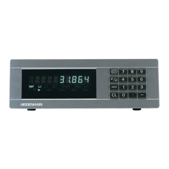
Working with the measured
value display unit
Actual value and input display
(7-segment LED,
9 decades and sign)
REF
<
=
HEIDENHAIN
Status display
• Switch display to:
MIN / MAX / DIFF / ACTL / START / PRINT
• Go to parameter list after switch-on
• Page forward in parameter list
Indicator
REF
in.
1 /
2
PRINT
SET
< / = / >
MIN / MAX
DIFF / ACTL
START
• Select datum
• Page backward in
1
2
SET
START
>
MIN
ACTL
Meaning
If the decimal points have stopped blinking:
Reference mark was crossed over — datum points are now stored
in nonvolatile memory.
Blinking: Waiting for operator to press ENT or CL.
Position values displayed in inches.
Datum 1 / Datum 2 currently active.
Blinking: Display unit is waiting for ENT for data output.
Blinking: Waiting for operator to confirm entry values.
Sorting mode: Measured value less than lower limit / within
tolerances / greater than upper limit.
Measuring series: Minimum / Maximum /
largest difference (MAX–MIN) / current measured value.
Blinking: Waiting for confirmation of value to be displayed.
Measuring series in progress.
Blinking: Waiting for start signal for measuring series.
ND 282
parameter list
PRINT
in.
MAX
DIFF
• Clear entry
• Reset to zero (P80!)
• CL plus MOD:
parameter list
• CL plus 2-digit num-
ber: select parameter
• Clear parameter entry
and show parameter
number
• Confirm entry value
• Set display to value from
P79 (P80!)
Numeric keypad
7
8
9
4
5
6
1
2
3
MOD
.
CL
0
–
• Algebraic
sign
• Decrease
parameter
value
• Decimal point
• Increase pa-
rameter value
Advertisement
Table of Contents

Related Manuals for HEIDENHAIN ND 282


Summary of Contents for HEIDENHAIN ND 282
- Page 1 HEIDENHAIN Working with the measured ND 282 value display unit • Confirm entry value • Set display to value from Actual value and input display • Select datum P79 (P80!) (7-segment LED, • Page backward in 9 decades and sign)
-
Page 2: Setting The Datum
The ND 282 is designed primarily for use with HEIDENHAIN MT Length Gauges. MT length gauges feature one reference mark. When the reference mark is crossed over, it generates a signal identifying that position as a reference point. After switch-on, simply crossing over the reference mark restores the relationship between axis positions and display values as it was last defined by datum setting. - Page 3 Measuring Series The ND 282 display unit can calculate and display one of the following values from a measuring series: Smallest value (MIN), largest value (MAX), difference between largest and smallest value (DIFF), last value measured (ACTL) A new value is captured every 550 µs during a measuring series.
-
Page 4: Data Output
Output instantaneous values referenced to datum 1 (MIN/MAX/DIFF display values are not output) A connecting cable (to a PC, for example) is available from HEIDENHAIN (Id.-Nr. 206 420 ..); cable length up to 10 m (32.8 ft). Operating parameters for data output: P23, P53 to P57 “AMP-CHAMP“... - Page 5 D-Sub Connection EXT (25-pin, male) Danger to internal components! Voltage sources for external circuitry must conform to the recommendations in EN 50 178 for low-voltage electrical separation. Connect inductive loads only with a quenching diode parallel to the inductance. Use only shielded cable! Connect the shield to the connector housing.
-
Page 6: Error Messages
Internal counter overflow Error while crossing over reference marks To clear the error message: Switch off the display unit. Should any of these error codes recur, contact your HEIDENHAIN service agency. Erase the operating parameters. If all decimal points light up, the measured value is too large or too small. -
Page 7: Operating Parameters
Operating Parameters The parameters are divided into “user parameters“ and “protected operating param- eters," which can only be accessed by entering a code number. User parameters User parameters are operating parameters that you can change without entering the code number: They are designated P00 to P30, P79, P86 Calling user parameters To call user parameters immediately after switch-on: Press the MOD key as long as... - Page 8 Parameter Meaning Function / Effect Setting Subdivision of encoder signals Subdivision 200, 100, 50, 40, 20, 10, 8, 5, 4, 2, 1, 0.8, 0.5, 0.4, 0.2, 0.1 Counting 0 - 1 - 2 - 3 - 4 - 5 - 6 - 7 - 8 - 9 - 0 mode 0 - 2 - 4 - 6 - 8 - 0 0 - 5 - 0...
- Page 9 Parameter Settings for HEIDENHAIN Linear Encoders Model P 43 Display step The following settings (unit: P01) apply for mm: inches Subdi- Count. Decimal vision mode places single 0,0005 0,00002 MT xx01 0,0002 0,00001 0,0001 0,000005 LIP 401 none 0,00005 0,000002...
-
Page 10: Rear Panel
X41 (EXT) interface 100 ... 240 V 50 ... 60 Hz Power switch Input for HEIDENHAIN linear encoder with Ground connection sinusoidal output signals (7µA to 16 µA connecting cable max. 30 m (98.5 ft), max. input frequency 50 kHz The X1, X33 and X41 interfaces comply with the recommendations in EN 50 178 for separation from line power.
Need help?
Do you have a question about the ND 282 and is the answer not in the manual?
Questions and answers