
Related Manuals for Emerson EIM PCU REV A4


Summary of Contents for Emerson EIM PCU REV A4
- Page 1 Installation and Maintenance Manual HQ-401-0217 Release: February 2017 HQ Proportional Control Unit (PCU-A)
-
Page 3: Table Of Contents
Service Instructions Table of Contents HQ-401-0217 February 2017 Table of Contents Section 1: Check Point Using Actuator ........1 Section 2: General Performance ..........1 Section 3: Standard Specification ..........2 Section 4: Function of PCU and How to Set and Use it ....3 Select input signal .................. - Page 4 Table of Contents Service Instructions February 2017 HQ-401-0217 Table of Contents (continued) Appendix A: List of Tables ............14 Appendix B: List of Figures ............. 14 Appendix C: List of Drawings Dwg. No. HQ-15000-A , 1 Ph Wiring Diagram PCU ........15 Dwg.
-
Page 5: Section 1: Check Point Using Actuator
Service Instructions Section 2: Checking Points HQ-401-0217 February 2017 Section 1: Check point before using actuator Check if specification (Model No., Main Power, Control Power, Options) of delivered actuator meets your requirements or not. Check the application such as valve, damper & etc. Check if mounting of actuator on application is correct and tight enough. -
Page 6: Section 3: Standard Specification
Section 3: Standard Specification Service Instructions February 2017 HQ-401-0217 Section 3: Standard Specification Model: PCU REV A4 Power: 85V-260VAC +10% 50/60Hz 4VA Max (New Wide range of voltage) Input signal: 4-20mA DC, 2-10V DC, 0-5V DC, 0-10V DC, 1-5V DC Input resistance: 250 Ohms, Feedback signal: 100 - 10K Ohm Output signal: 4-20mA DC, 2-10V DC, 0-5V DC, 0-10V DC, 1-5V DC Load resistance: 500 Ohms Max. -
Page 7: Section 4: Function Of Pcu And How To Set And Use It
Service Instructions Section 4: Function of a PCU HQ-401-0217 February 2017 Section 4: Function of a PCU and how to set and use it Selecting of the input signal User can select suitable input signal by adjusting DIP switches as follows. Figure 2 Input DIP switch Select input signal... -
Page 8: Delay Time
Section 4: Function of a PCU Service Instructions February 2017 HQ-401-0217 Delay Time This prevents continuous operation of PCU card caused by abnormal signal input such as noise, microphone and other foreign frequency. Once the signal is detected, PCU follows that signal but if there is a preset time, PCU doesn't move within the time. -
Page 9: Manual Operation
Service Instructions Section 4: Function of a PCU HQ-401-0217 February 2017 Manual operation by PCU card In order to operate actuator by card, press ZERO and SPAN buttons together for 2 seconds. The yellow LED will turn on to confirm manual operation mode. If ZERO button is pushed, actuator will move to close and if the SPAN button is pushed, the actuator will move to open. -
Page 10: Auto Setting
Section 4: Function of a PCU Service Instructions February 2017 HQ-401-0217 AUTO SETTING If mounting between actuator and application is correct, and input signal, input power and wiring are correct, push AUTO SETTING button just once regardless of the position of actuator. -
Page 11: Reversal Acting Switch (Ch2)
Service Instructions Section 4: Function of a PCU HQ-401-0217 February 2017 Figure 9 CH1 DIP switch OPEN AUTO CLOSE FAULT zero span AUTO F CLOSE close open SETTING F OPEN LD1 LD2 LD3 LD4 A FULL 1 2 3 4 5 VIEW C Reversal acting switch (CH2) Generally, clockwise-rotating direction of actuator is to close but if user wants reverse... -
Page 12: Selection Of Output Signal
Section 4: Function of a PCU Service Instructions February 2017 HQ-401-0217 4.10 Selection of output signal The user can select suitable output signal by adjusting DIP switches as follows: Figure 11 Output selection DIP switch 0 - 10V DC 4 - 20mA DC 2 - 10V DC Select output signal 0 - 5V DC... -
Page 13: Section 5: Special Tools
Service Instructions Section 5: Special Tools HQ-401-0217 February 2017 Section 5: Special tools L -Wrench 1 set (metric) Screw driver(-) Monkey spanner (1 set) DC signal generator (0-24mA DC) Multi-meter mA DC meter (0-25mA DC) Section 6: Setting potentiometer (Replacing and setting) Put actuator into full close position Take P1 and P2 and measuring its resistance, turn potentiometer until it reaches a value between 30 -100 Ohm. -
Page 14: Section 7: Limit Switch Setting
Section 7: Limit Switch Setting Service Instructions February 2017 HQ-401-0217 Section 7: Limit switch setting Pull over the lever for manual operation and turn hand wheel to move actuator to full close (or open) position. Loosen the bolts tightening cam by L-wrench, and turn CLS (or OLS) cam to CW (or to CCW), so that cam may hit the lever of close (or open) limit switch. -
Page 15: Section 8: Check Operation Of Pcu
Service Instructions Section 8: Check Operation of PCU HQ-401-0217 February 2017 Section 8: Check operation of PCU Table 1. PCU operation legend Actuator Full Close Full Open Input signal 4mA DC (1V DC, 2V DC) 20mA DC (5V DC, 10V DC) 4mA DC Output signal 20mA DC... -
Page 16: Pcu Card Pcb Layout And Function Highlight Views
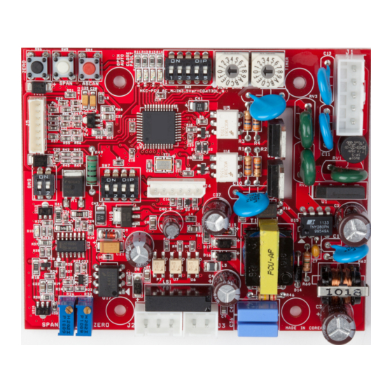
Section 9: Layout of PCU Card Service Instructions February 2017 HQ-401-0217 Figure 15 PCU Card PCB layout and function highlight views View E View A View C View D View F View B Layout of PCU Card... -
Page 17: Section 10: Document Revision
Service Instructions Section 10: Document Revision HQ-401-0217 February 2017 Section 10: Document Revision Table 2. Revision Overview DATE BY * DATE Released COMPILED C. Rico December 2013 Reviewed CHECKED D. Hoke December 2013 December 2013 Approved APPROVED D. Hoke December 2013 Document Revision... -
Page 18: Appendix A: List Of Tables
Appendix Service Instructions February 2017 HQ-401-0217 Appendix A: List of Tables Table 1. PCU Operation Legend ..................11 Table 2. Revision Overview ....................13 Appendix B: List of Figures Figure 1. PCB LED Panel ....................... 2 Figure 2. Input DIP switch .................... -
Page 19: Appendix C: List Of Drawings
Service Instructions Appendix HQ-401-0217 February 2017 Appendix C: List of Drawings Dwg. No. HQ-15000-A , 1 Ph Wiring Diagram PCU Appendix... -
Page 20: Dwg. No. Hq-1500-A , 1 Ph Wiring Diagram Std
Appendix Service Instructions February 2017 HQ-401-0217 Dwg. No. HQ-1500-A , 1 Ph Wiring Diagram Std. Appendix... - Page 22 We reserve the right to modify or improve the designs or specifications of the products mentioned in this manual at any time without notice. Emerson does not assume responsibility for the selection, use or maintenance of any product. Responsibility for proper selection, use and maintenance of any Emerson product remains solely with the purchaser.
Need help?
Do you have a question about the EIM PCU REV A4 and is the answer not in the manual?
Questions and answers