Advertisement
Description
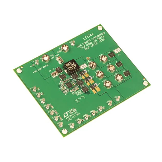
Demonstration circuit 2339A is a high current synchronous
step-down LED driver featuring the
drive stage used on the LT3744 allows the anodes of three
LEDs to be connected together for better heat sinking. This
connection will work in both the step-down configuration
and the inverting buck-boost configuration. The pros and
cons of each configuration can be found in the data sheet.
This demonstration circuit 2339A is for customers to test
the step-down configuration only. The inverting buck-boost
configuration is shown in a separate demonstration circuit.
The input of the demo board is up to 36V. The components
are optimized for the efficiency, thermal and PWM dim-
ming for a 12V input. Each of the three outputs is up to
5V, 20A with a 6.05V maximum output voltage limit. The
PWM1, PWM2 and PWM3 pins are set to low by default.
A DC or PWM signal is required to connect to at least one
of the PWM pins to enable the circuit. At any giving time,
output current only passes through one LED determined
by settings of PWM pins.
The CTRL1, CTRL2 and CTRL3 pins can be adjusted to
provide accurate analog dimming down to 20:1 ratio.
The minimal input voltage for the LT3744 to operate is
3.3V. However, to maintain the output current regulation
in a step down regulator, the minimum input voltage is
determined by the LED voltage and the maximum duty cycle.
For a 5V output, the demo board minimum input voltage
will be around 5.5V at room temperature. The load to be
used with this demo board is high current LEDs or laser
diodes. Smaller LEDs may not be able to handle the high
current, even for a short period of time. It is necessary
to mount the LED load on a proper heat sink. A fan may
become necessary to avoid exceeding LED's maximum
temperate rating.
The typical efficiency of the demo board is 93.5% from
LT
3744. The unique
a 12V input to 5V, 20A load. The lower the input voltage,
®
the higher the efficiency tends to be for a given load. At
output power level of 100W, even one percent of efficiency
improvement is a big advantage in minimizing temperature
rise. If an efficiency measurement is needed in an applica-
tion, the output voltage must be measured at the output
capacitors instead of the LED load. This prevents cable
loss from being counted as a loss of the board.
The demo circuit DC2399A achieves fast current rise time
from 0A to 20A in 5µs. To see the real rise time, connecting
wires between the LED and the board should be as short as
possible to minimize the wire inductance and resistance. It
is recommended to measure the voltage across R32 with
a short 50Ω coax cable directly into a BNC connector on
the oscilloscope. The current can be calculated from the
measured voltage. Figure 1 shows the current rise time. A
current probe adds more delays to the rise time so using
a current probe is not recommended unless rise time is
not a concern.
The LT3744 data sheet gives a complete description of
the part, operation and application information. The data
sheet must be read in conjunction with this quick start
guide for demo circuit 2339A.
Design files for this circuit board are available at
http://www.linear.com/demo/DC2339A
L, LT, LTC, LTM, Linear Technology and the Linear logo are registered trademarks of Linear
Technology Corporation. All other trademarks are the property of their respective owners.
DEMO MANUAL DC2339A
High Current Synchronous
Step-Down LED Driver
LT3744
dc2339af
1
Advertisement
Table of Contents

Related Manuals for Linear Technology DC2339A


Summary of Contents for Linear Technology DC2339A
- Page 1 5.5V at room temperature. The load to be L, LT, LTC, LTM, Linear Technology and the Linear logo are registered trademarks of Linear used with this demo board is high current LEDs or laser Technology Corporation. All other trademarks are the property of their respective owners.
-
Page 2: Performance Summary
Description 2V/DIV (YELLOW) 2V/DIV LED CURRENT (GREEN) 6.67A/DIV 2.00µs/DIV Figure 1. DC2339A Current Rise Time. V = 12V, LED Voltage = 4.2V when ON. Total LED Current = 20A performance summary Specifications are at T = 25°C SYMBOL PARAMETER CONDITIONS... - Page 3 DEMO MANUAL DC2339A Quick start proceDure – – INPUT SUPPLY – DC or DC or DC or Figure 2. Proper Measurement Equipment Setup dc2339af...
-
Page 4: Parts List
DEMO MANUAL DC2339A parts List ITEM REFERENCE PART DESCRIPTION MANUFACTURER/PART NUMBER Required Circuit Components C1, C2, C24, C25, C30, C31 CAP., X7R, 10µF, 50V, 10%, 1210 MURATA, GRM32ER71H106KA12L C4, C5 CAP., ALUM., ELECT., 56µF, 50V SUN ELECT., 50HVT56M CAP., X7R, 0.22µF, 25V, 10% 0603 MURATA, GRM188R71E224KA88D CAP., X7R, 1µF, 50V, 10% 0805... -
Page 5: Schematic Diagram
Information furnished by Linear Technology Corporation is believed to be accurate and reliable. However, no responsibility is assumed for its use. Linear Technology Corporation makes no representa- tion that the interconnection of its circuits as described herein will not infringe on existing patent rights. - Page 6 Linear Technology Corporation (LTC) provides the enclosed product(s) under the following AS IS conditions: This demonstration board (DEMO BOARD) kit being sold or provided by Linear Technology is intended for use for ENGINEERING DEVELOPMENT OR EVALUATION PURPOSES ONLY and is not provided by LTC for commercial use. As such, the DEMO BOARD herein may not be complete in terms of required design-, marketing-, and/or manufacturing-related protective considerations, including but not limited to product safety measures typically found in finished commercial goods.
- Page 7 Мы молодая и активно развивающаяся компания в области поставок электронных компонентов. Мы поставляем электронные компоненты отечественного и импортного производства напрямую от производителей и с крупнейших складов мира. Благодаря сотрудничеству с мировыми поставщиками мы осуществляем комплексные и плановые поставки широчайшего спектра электронных компонентов.
Need help?
Do you have a question about the DC2339A and is the answer not in the manual?
Questions and answers