Advertisement
Quick Links
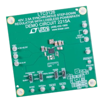
Description
Demonstration Circuit 2215A, features the
synchronous buck converter with an integrated lossless
input PowerPath™. Pin selectable (JP2) ideal diode-OR
and priority input modes, with programmable undervolt-
age lockout thresholds provide control over the transi-
tion between input sources. The unique all N-channel
architecture provides efficient operation from either of
two input sources to a programmable output voltage.
In this application the valid input voltage range is set
to be from 4.3V to 42V on V
V
providing flexibility and voltage margin for a variety
IN2
of applications and power sources. V
42V. Other input voltage ranges are possible by adjusting
V
accordingly.
SET1/2
The LTC3126 uses a low noise, current mode architec-
ture and a resistor programmable (R13) PWM oscillator
frequency which is also synchronizable from 200kHz to
2.2MHz. This minimizes the solution footprint while ensur-
ing high efficiency. For higher efficiency at light loads, the
user can select Burst Mode
Typical efficiencies for both PWM mode (JP1 = PWM)
and Burst Mode operation (JP1 = BURST) are shown
in Figure 1. Burst Mode operation allows the automatic
transition to PWM operation if the load current increases.
This is shown in Figure 5. More information on Burst Mode
operation and PWM mode can be found in the data sheet.
Input Voltage Range V
Input Voltage Range V
42V, 2.5A Synchronous Step-Down
Regulator with Lossless PowerPath
LTC
3126, a
®
and from 6V to 8.4V on
IN1
can operate to
IN2
operation (JP1).
®
IN1
IN2
V
OUT
I
OUT
DEMO MANUAL DC2215A
In some applications the efficiency can be improved by
setting the EXTV
jumper (JP3) to V
CC
converter to operate from the fixed V
performance in response to a transient load is shown in
Figure 4.
The system can be monitored through VALID1, VALID2,
PRIORITY and PGOOD indicators. There are accurate
V
and V
comparators to program independent
SET1
SET2
UVLO thresholds. Consult the data sheet for information
on start-up and shutdown thresholds. Other features
include a 1μA shut-down current (ENA pin JP4 = OFF),
short-circuit protection, soft-start, inductor current limit
and thermal overload protection.
The LTC3126 data sheet has detailed information about
the operation, specifications, and applications of the part.
The data sheet should be read in conjunction with this
Quick Start Guide.
Design files for this circuit board are available at
http://www.linear.com/demo/DC2215A
L, LT, LTC, LTM, Linear Technology, the Linear logo and Burst Mode are registered trademarks
and PowerPath is a trademark of Linear Technology Corporation. All other trademarks are the
property of their respective owners.
4.3V to 42.0V
6.0V to 8.4V (Operational to 42V)
LTC3126UFD
. This allows the
OUT
voltage. Typical
OUT
3.3V
2.5A
dc2215af
1
Advertisement

Related Manuals for Linear Technology LTC3126UFD


Summary of Contents for Linear Technology LTC3126UFD
- Page 1 Typical efficiencies for both PWM mode (JP1 = PWM) L, LT, LTC, LTM, Linear Technology, the Linear logo and Burst Mode are registered trademarks and PowerPath is a trademark of Linear Technology Corporation. All other trademarks are the and Burst Mode operation (JP1 = BURST) are shown property of their respective owners.
- Page 2 DEMO MANUAL DC2215A Burst Mode OPERATION PWM MODE = 4.5V = 12V = 25V 0.0001 0.001 0.01 LOAD CURRENT(A) DC2215A F01 Figure 1. Typical Efficiency as a Function of Input Voltage and Load Current PRIORITY MODE OPERATION = 2V/DIV = 2V/DIV = 1V/DIV TRANSITION TRANSITION...
- Page 3 DEMO MANUAL DC2215A IDEAL DIODE MODE OPERATION TRANSITION TO V = 2V/DIV = 2V/DIV = 1V/DIV TRANSITION TO V LOAD = 5 DC2215A F03 2ms/DIV Figure 3. The LTC3126 Monitors the Voltage on V and V and Selects the Higher of These Voltages in Ideal Diode 3.3V 200mV/DIV OUTPUT...
- Page 4 DEMO MANUAL DC2215A AUTOMATIC AUTOMATIC TRANSITION FROM TRANSITION FROM Burst Mode TO PWM PWM TO Burst Mode Burst Mode OPERATION OUTPUT VOLTAGE PWM OPERATION 100mV/DIV Burst Mode RIPPLE OUTPUT CURRENT 500mA/DIV 600mA 100mA DC2215A F05 2ms/DIV Figure 5. Output Ripple and Transients in Burst Mode Operation and Transitioning from and into Burst Mode Operation dc2215af...
-
Page 5: Quick Start Procedure
DEMO MANUAL DC2215A Quick start proceDure Using short twisted pair leads for any power connections Jumpers and with all loads and power supplies off, refer to Figure 6 JP1/PWM/SYNCH: Selects PMW or Burst Mode opera- for the proper measurement and equipment setup. The tion. - Page 6 DEMO MANUAL DC2215A Quick start proceDure 8. Repeat steps 4 to 6 with V . With V off increase 11. By adjusting the voltage on V from 10V to 0V and from 0V to 8.4V. The part will turn on when V back the converter operates from V while V is approximately 6V.
- Page 7 DEMO MANUAL DC2215A Quick start proceDure dc2215af...
-
Page 8: Parts List
DEMO MANUAL DC2215A parts List ITEM REFERENCE PART DESCRIPTION MANUFACTURER/PART NUMBER Required Circuit Components C1, C2, C8 CAP CER 0.1µF 50V 10% X7R 0805 MURATA, GRM21BR71H104KA01L C3, C4 CAP CER 10µF 50V 10% X7R 1210 MURATA, GRM32ER71H106KA12L C7, C15 CAP CER 47µF 10V 10% X7R 1210 MURATA, GRM32ER71A476KE15L CAP CER 10pF 50V 5% NP0 0402 MURATA, GRM1555C1H100JA01D... -
Page 9: Schematic Diagram
Information furnished by Linear Technology Corporation is believed to be accurate and reliable. However, no responsibility is assumed for its use. Linear Technology Corporation makes no representa- tion that the interconnection of its circuits as described herein will not infringe on existing patent rights. - Page 10 Linear Technology Corporation (LTC) provides the enclosed product(s) under the following AS IS conditions: This demonstration board (DEMO BOARD) kit being sold or provided by Linear Technology is intended for use for ENGINEERING DEVELOPMENT OR EVALUATION PURPOSES ONLY and is not provided by LTC for commercial use. As such, the DEMO BOARD herein may not be complete in terms of required design-, marketing-, and/or manufacturing-related protective considerations, including but not limited to product safety measures typically found in finished commercial goods.
- Page 11 Mouser Electronics Authorized Distributor Click to View Pricing, Inventory, Delivery & Lifecycle Information: Analog Devices Inc. DC2215A...
Need help?
Do you have a question about the LTC3126UFD and is the answer not in the manual?
Questions and answers