Table of Contents
Advertisement
Quick Links
LTC4124/LTC4125, 100mA Wireless Li-Ion Charger
DESCRIPTION
DC2770A-B-KIT is a kit of the DC2773A-B transmitter
board (featuring
LTC
4125) and the DC2775A-D (featuring
®
LTC
4124). The DC2775A-D receiver board can charge
®
a single Li-Ion battery at up to 100 mA with an air gap of
3.0 mm to 5.0 mm between the transmit and receive coils.
CONTENTS
1 × DC2773A-B (LTC4125) Transmitter Demo Board
1 × DC2775A-D (LTC4124) Receiver Demo Board
PERFORMANCE SUMMARY
SYMBOL
PARAMETER
V
DC2773A-B Voltage Input
IN
I
DC2773A-B V
Current
IN
IN
V
DC2775A-D Battery Charge Voltage
BAT
I
DC2775A-D Charge Current
BAT
AIR-GAP
Separation Between L
f
DC2773A-B Resonant Tank Frequency
TX_TANK
f
DC2775A-D Resonant Tank Frequency
RX_TANK
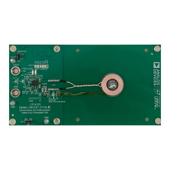
BOARD PHOTO
Figure 1. DC2773A-B Picture
CONDITIONS
I
≤ 500mA
VIN
V
= 5V
IN
V
SEL1
V
SEL1
V
SEL1
V
SEL1
V
BAT
and L
Coils
TX
RX
DEMO MANUAL DC2770A-B-KIT
The DC2773A-B transmitter supports Optimum Power
Search and Foreign Object Detection features via LTC4125.
Design files for this circuit board are
All registered trademarks and trademarks are the property of their respective owners.
= HI, V
= HI
SEL2
= HI, V
= LO
SEL2
= LO, V
= HI
SEL2
= LO, V
= LO
SEL2
= 4.0V, I
= V
, I
= V
SEL1
CC
SEL2
CC
Figure 2. DC2775A-D Picture
Demonstration Kit
available.
MIN
TYP
MAX
4.5
5.5
500
4.35
4.20
4.1
4.00
100
3
3.5
200
200
UNITS
V
mA
V
V
V
V
mA
5
mm
kHz
kHz
Rev. 0
1
Advertisement
Table of Contents

Related Manuals for Linear Technology Analog Devices DC2773A-B


Summary of Contents for Linear Technology Analog Devices DC2773A-B
- Page 1 DEMO MANUAL DC2770A-B-KIT LTC4124/LTC4125, 100mA Wireless Li-Ion Charger Demonstration Kit DESCRIPTION DC2770A-B-KIT is a kit of the DC2773A-B transmitter The DC2773A-B transmitter supports Optimum Power board (featuring 4125) and the DC2775A-D (featuring Search and Foreign Object Detection features via LTC4125. ®...
-
Page 2: Quick Start Procedure
DEMO MANUAL DC2770A-B-KIT QUICK START PROCEDURE Refer to Figures 3, 4, and 5 for the proper measurement only sources current even when the battery charge cur- equipment setup, DC2775A-D mounting on DC2773A-B, rent is at its maximum value. and follow the procedure below: 4. -
Page 3: Test Setup
DEMO MANUAL DC2770A-B-KIT TEST SETUP Battery Emulator – RBAT1 3.7V DC 0.5A – Figure 4. DC2775A-D Top 4.5–5.5V Supply 0.5A – Figure 5. DC2773A-B Top Rev. 0... - Page 4 DEMO MANUAL DC2770A-B-KIT TEST SETUP Figure 6. Measuring Input or Output Ripple NOTE: All connections from equipment should be Kelvin connected directly to the board pins which they are connected on this diagram and any input or output leads should be twisted pair. Rev.
-
Page 5: Theory Of Operation
DEMO MANUAL DC2770A-B-KIT THEORY OF OPERATION The DC2770A-B-KIT demonstrates operation of a mag- The LTC4125 monitors the FB pin, and when a valid exit netically coupled resonant Wireless Power Transfer (WPT) condition is found, it stops incrementing the PTH volt- system. - Page 6 DEMO MANUAL DC2770A-B-KIT THEORY OF OPERATION 2V/DIV 2V/DIV BAT_LTC4124 50mA/DIV ACIN 2V/DIV PTH_LTC4125 500mV/DIV FB_LTC4125 1V/DIV 50ms/DIV Figure 8. Rectification of AC Input and Regulation of V Figure 9. LTC4124 Shunting Event Triggering Exit Condition for LTC4125 to Stop the Search Algorithm As shown in Figure ...
-
Page 7: Parts List
DEMO MANUAL DC2770A-B-KIT PARTS LIST ITEM REFERENCE PART DESCRIPTION MANUFACTURER/PART NUMBER DC2773A-B: Required Circuit Components CAP . 100uF 6.3V 1206 MURATA GRM31CR60J107KE39L CAP . 0.01uF 0402 KEMET C0402C103K5RAC7867 CAP . 0.68uF 0402 YAGEO CC0402KRX5R6BB684 CAP . 4700pF 0402 04025C472KAT2A CAP . 680pF 0402 KEMET... - Page 8 DEMO MANUAL DC2770A-B-KIT ITEM REFERENCE PART DESCRIPTION MANUFACTURER/PART NUMBER RES. 10k OHMS 1/16W 0402 YAGEO RC0402JR-0710KL RES. 430 OHMS 1/16W 0402 YAGEO RC0402JR-07430RL RES. 15.4k OHMS 1/16W 0402 AEC-Q200 KOA SPEER RK73H1ETTP1542F RES. 27.4k OHMS 1/16W 0402 AEC-Q200 VISHAY CRCW040227K4FKED RES.
-
Page 9: Schematic Diagram
DEMO MANUAL DC2770A-B-KIT SCHEMATIC DIAGRAM Rev. 0... - Page 10 DEMO MANUAL DC2770A-B-KIT SCHEMATIC DIAGRAM Rev. 0...
- Page 11 DEMO MANUAL DC2770A-B-KIT SCHEMATIC DIAGRAM Rev. 0 Information furnished by Analog Devices is believed to be accurate and reliable. However, no responsibility is assumed by Analog Devices for its use, nor for any infringements of patents or other rights of third parties that may result from its use. Specifications subject to change without notice.
- Page 12 DEMO MANUAL DC2770A-B-KIT ESD Caution ESD (electrostatic discharge) sensitive device. Charged devices and circuit boards can discharge without detection. Although this product features patented or proprietary protection circuitry, damage may occur on devices subjected to high energy ESD. Therefore, proper ESD precautions should be taken to avoid performance degradation or loss of functionality. Legal Terms and Conditions By using the evaluation board discussed herein (together with any tools, components documentation or support materials, the “Evaluation Board”), you are agreeing to be bound by the terms and conditions set forth below (“Agreement”) unless you have purchased the Evaluation Board, in which case the Analog Devices Standard Terms and Conditions of Sale shall govern.
Need help?
Do you have a question about the Analog Devices DC2773A-B and is the answer not in the manual?
Questions and answers