
Subscribe to Our Youtube Channel
Related Manuals for Planet IFGS-1822TF


Summary of Contents for Planet IFGS-1822TF
- Page 1 Industrial 16-Port 10/100TX + 2-Port Gigabit TP/SFP Combo Ethernet Switch IFGS-1822TF User’s Manual...
- Page 2 PLANET has made every effort to ensure that this User’s Manual is accurate; PLANET disclaims liability for any inaccuracies or omissions that may have occurred.
- Page 3 Do not dispose of WEEE as unsorted municipal waste and have to collect such WEEE separately. Revision PLANET Industrial 16-Port 10/100TX + 2-Port Gigabit TP/SFP Combo Ethernet Switch User's Manual Model: IFGS-1822TF Revision: 2.0 (Oct. 2022)
-
Page 4: Table Of Contents
Table of Contents 1. Package Contents ................. 5 2. Product Specifications ................6 3. Hardware Introduction ................8 3.1 Switch Front Panel ................. 8 3.2 LED Definition ................9 3.3 Switch Upper Panel ...............10 3.4 Wiring the Power Inputs ..............10 3.5 Wiring the Fault Alarm Contact ............12 4. -
Page 5: Package Contents
1. Package Contents Thank you for purchasing PLANET Industrial Multi-port 10/100TX Fast Ethernet Switch, IFGS-1822TF. In the following sections, the term “Industrial Ethernet Switch” means the IFGS-1822TF. Open the box of the Industrial Ethernet Switch and carefully unpack it. The... -
Page 6: Product Specifications
2. Product Specifications IFGS-1822TF Product Hardware Specifications Fast Ethernet Copper Ports 16 10/100BASE-TX RJ45 auto-MDI/MDI-X ports Two 10/100/1000BASE-T RJ45 auto-MDI/MDI-X Gigabit Ethernet Copper ports Ports (shared with Port 17 and Port 18) Two 1000BASE-SX/LX/BX SFP interfaces SFP Slots (shared with Port 17 and Port 18) - Page 7 Standards Conformance Regulatory Compliance FCC Part 15 Class A, CE IEC60068-2-32 (free fall) Stability Testing IEC60068-2-27 (shock) IEC60068-2-6 (vibration) IEEE 802.3 10BASE-T IEEE 802.3u 100BASE-TX IEEE 802.3ab Gigabit 1000T Standards Compliance IEEE 802.3z Gigabit SX/LX IEEE 802.3x flow control and back pressure IEEE 802.1p Class of Service IEEE 802.3az Energy Efficient Ethernet (EEE) Environment...
-
Page 8: Hardware Introduction
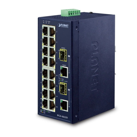
3. Hardware Introduction 3.1 Switch Front Panel The front panel of the Industrial Ethernet Switch consists of Ethernet interfaces and LED indicators Front View P2 Alarm 1000X 挖孔 1000T IFGS-1822TF Figure 1: IFGS-1822TF Front View... -
Page 9: Led Definition
3.2 LED Definition System Function Color Green Lights to indicate power input 1 has power. Green Lights to indicate power input 2 has power. Alarm Lights to indicate either power 1 or power 2 has no power. Per 10/100BASE-TX Port Function Color Lights to indicate the link through that port is successfully established. -
Page 10: Switch Upper Panel
PWR2 AC Input: 24V , 1A max. Figure 2: IFGS-1822TF Top View 3.4 Wiring the Power Inputs The 6-contact terminal block connector on the top panel of Industrial Ethernet Switch is used for two redundant power inputs. Please follow the steps below to insert the power wire. - Page 11 2. Tighten the wire-clamp screws for preventing the wires from loosening. Power 1 Alarm Power 2 1. The wire gauge for the terminal block should be in the range between 12 and 24 AWG. 2. The power input range is 12V ~ 48V DC and supports 24V 3.
-
Page 12: Wiring The Fault Alarm Contact
3.5 Wiring the Fault Alarm Contact The fault alarm contacts are in the middle of the terminal block connector as the picture shows below. Inserting the wires, the Industrial Ethernet Switch will detect the fault status of the power failure and then forms an open circuit. The following illustration shows an application example for wiring the fault alarm contacts. -
Page 13: Installation
DIN rail and wall. Please read this chapter completely before continuing. This following pictures show how to install the device. However, the device in the picture is not IFGS-1822TF. 4.1 DIN-rail Mounting Installation 4.2 Wall-mount Plate Mounting... -
Page 14: Side Wall-Mount Plate Mounting
4.3 Side Wall-mount Plate Mounting 4.4 Grounding the Device User MUST complete grounding wired with the device; otherwise, a sudden lightning could cause fatal damage to the device. EMD (Lightning) DAMAGE IS NOT CONVERED UNDER WARRANTY. Max. Fault Alarm Loading: 24V, 1A 1 2 3 4 5 6 V1+ V1- V2+ V2-... -
Page 15: Customer Support
5. Customer Support Thank you for purchasing PLANET products. You can browse our online FAQ resource on PLANET web site first to check if it could solve your issue. If you need more support information, please contact PLANET switch support team.
Need help?
Do you have a question about the IFGS-1822TF and is the answer not in the manual?
Questions and answers