Turbosound MANCHESTER Series User Manual
Hide thumbs
Also See for MANCHESTER Series:
- Rigging manual (54 pages) ,
- Manual (48 pages) ,
- Quick start manual (13 pages)
Table of Contents
Advertisement
Quick Links
User Manual
MANCHESTER SERIES
MAN210-FG
Universal Fly Grid for MANCHESTER MV210-HC Array Elements and MS121 subwoofers
MS121
Single 21" Front Loaded Subwoofer for Touring and Install Applications
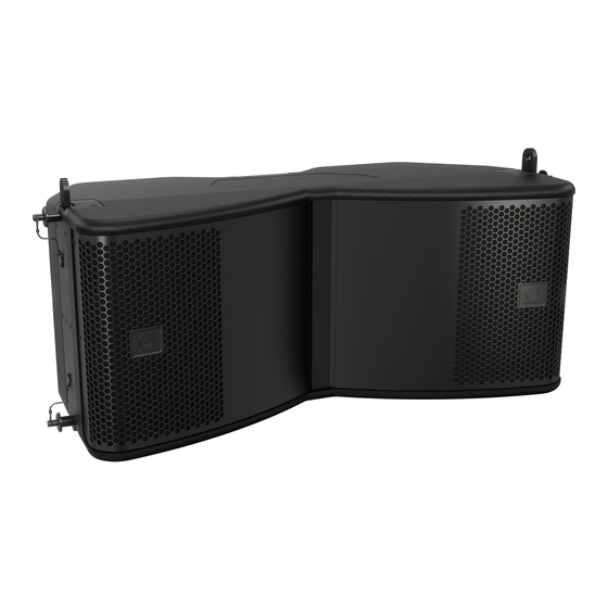
MV210-HC
Full Size Dual 10" Hybrid Curve Element for Install and Touring
MS121-VT
Vertical Transporter for MANCHESTER MS121 Subwoofer elements
MV210-VT
Vertical Transporter for MANCHESTER MV210-HV array elements
!
WARNING!
This rigging manual contains important safety information, and it must be kept in a safe place for future reference. It must be supplied with the equipment
during the original sale, rental, or re-sale, and all operators and users of the equipment must be made aware that this manual is available. Please visit our website
turbosound.com regularly and check for any updates to this manual.
V 1.0
Advertisement
Table of Contents

Subscribe to Our Youtube Channel
Related Manuals for Turbosound MANCHESTER Series


Summary of Contents for Turbosound MANCHESTER Series
- Page 1 Please visit our website turbosound.com regularly and check for any updates to this manual. V 1.0...
-
Page 2: Table Of Contents
Manchester Series MAN210-FG/MS121/MAN210-HC Rigging Manual Table of Contents Safety Instruction ............3 LEGAL DISCLAIMER ............3 LIMITED WARRANTY ............3 Chapter 1: Safety Information ........4 Chapter 2: Introduction ..........6 Chapter 3: Assembling an MV210-HC Array on a MAN210-FG Fly Grid ........30 Chapter 4: Assembling MS121 Subwoofers on a MAN210-FG Fly Grid ........ -
Page 3: Safety Instruction
Technical specifications, appearances and other information are subject to change without notice. All trademarks are the property of their respective owners. Midas, Klark Teknik, Lab Gruppen, Lake, Tannoy, Turbosound, TC Electronic, TC Helicon, Behringer, Bugera, Aston Microphones and Coolaudio are trademarks or registered trademarks of Music Tribe Global Brands Ltd. -
Page 4: Chapter 1: Safety Information
We also recommend you schedule Turbosound line array training with our sales partners and applications team. Equipment used to connect to the Turbosound rigging system must be properly rated and must conform to the local, state and other safety regulations. Do not use Turbosound rigging with other types or brands of loudspeakers. - Page 5 Manchester Series MAN210-FG/MS121/MAN210-HC Rigging Manual 1.7 Secondary Safeties All loudspeakers flown in theatres, studios or other places of work and entertainment shall, in addition to the principle load bearing means of suspension, be provided with an independent, properly rated, and securely attached secondary safety. Only steel wire ropes or steel chains of an approved construction and load rating shall be used as secondary safeties.
-
Page 6: Chapter 2: Introduction
Manchester Series MAN210-FG/MS121/MAN210-HC Rigging Manual Chapter 2: Introduction 2.1 Typical Configurations MV210-HC Array (See Chapter 3) MS121 and MV210-HC Mixed Array (See Chapter 5) MS121 Array (See Chapter 4) - Page 7 Manchester Series MAN210-FG/MS121/MAN210-HC Rigging Manual MV210-HC Array Groundstack (See Chapter 8) Two MS121 Subwoofer Groundstack (See Chapter 6) MS121 and MV210-HC Groundstack (See Chapter 7)
- Page 8 Manchester Series MAN210-FG/MS121/MAN210-HC Rigging Manual 2.2 Rigging and Acoustic Simulation Software The EASE FOCUS 3 software allows you to configure the system for optimal performance and coverage in the venue. The software can be downloaded from http://www.afmg.eu/index.php/products.html The quantity of cabinets can be varied, the angles of each cabinet can be adjusted, and the SPL coverage calculated for any configuration.
- Page 9 Manchester Series MAN210-FG/MS121/MAN210-HC Rigging Manual 2.2.2 EASE example: Array MV210-HC x 8, with MAN210-FG Tip Bar Centered This example uses the Tip Bar mounted in the center position of the MAN FG fly grid. Note: for systems that do not require much variation in the tilt angle, and in systems that only require one main hoist, the single shackle plate can be used instead of...
- Page 10 Manchester Series MAN210-FG/MS121/MAN210-HC Rigging Manual 2.2.3 EASE FOCUS 3 example: Array MV210-HC x 8, with MAN210-FG Tip Bar Mounted Rearwards This example uses the Tip Bar mounted in the rear position on the MAN210-FG fly grid. Using the Tip Bar in this position will make the array's Centre of Gravity force...
- Page 11 Manchester Series MAN210-FG/MS121/MAN210-HC Rigging Manual 2.2.4 EASE FOCUS 3 example: Array MV210-HC x 8, with MAN210-FG Tip Bar Mounted Forwards This example uses the Tip Bar mounted in the forward position on the MAN210-FG fly grid. Using the Tip Bar in this position will make the array's Centre of Gravity...
- Page 12 Manchester Series MAN210-FG/MS121/MAN210-HC Rigging Manual 2.2.5 EASE FOCUS 3 example: Array MV210-HC x 15, with MAN210-FG Tip Rearwards This example uses the Tip Bar mounted in the rear position on the MAN210-FG fly grid. All four rigging pins are used to secure the Tip Bar to the MAN210-FG fly grid.
- Page 13 Manchester Series MAN210-FG/MS121/MAN210-HC Rigging Manual 2.2.6 EASE FOCUS 3 example: Mixed Array MS121 x 6, MV210-HC x 16, with MAN210-FG Tip Bar Mounted Rearwards This example uses the Tip Bar mounted in the rear position on the MAN210-FG fly grid. All four rigging pins are used to secure the Tip Bar to the MAN210-FG fly grid.
- Page 14 Manchester Series MAN210-FG/MS121/MAN210-HC Rigging Manual 2.2.7 EASE FOCUS 3 example: Groundstack of MV210-HC x 10, with MAN210-FG and Outriggers This example shows a groundstack of MV210-HC cabinets on the MAN210-FG fly grid with its outriggers attached. Warning: Do not physically build the configuration shown in this EASE example, as it has more than 6 MV210-HC cabinets. The number of cabinets has been purposely...
- Page 15 Manchester Series MAN210-FG/MS121/MAN210-HC Rigging Manual 2.2.8 EASE FOCUS 3 example: Mixed Groundstack of MS121 x 3 and MV210-HC x 7, with one MAN210-FG This example shows a mixed groundstack of MS121 subwoofers, and MV210-HC cabinets on the MAN210-FG fly grid.
- Page 16 Manchester Series MAN210-FG/MS121/MAN210-HC Rigging Manual 2.3 MV210-HC Cabinet Angles The angle of each MV210-HC cabinet relative to the cabinet above it, is varied by moving the sliding mount plate and inserting the quick release pin into one of the mounting holes in the rear mounting bracket. These are labeled from 0 to 20 degrees.
- Page 17 Manchester Series MAN210-FG/MS121/MAN210-HC Rigging Manual 2.4 Rigging Pin installation in the MV210-HC rear mounting plate This drawing shows the pin locations used to set the angle of the cabinet relative to the cabinet above (0 degrees = Parallel to the cabinet above).
- Page 18 Manchester Series MAN210-FG/MS121/MAN210-HC Rigging Manual 2.6 Weights Item Quantity Weight (kg) Weight (lbs) MAN210-FG with Tip Bar 32.8 72.3 and pick points MV210-HC 35.5 78.3 MS121 87.5 192.9 2.7 MAN210-FG Fly Grid Working Load Limit (WLL) Item WLL (kg) WLL (lbs)
- Page 19 Manchester Series MAN210-FG/MS121/MAN210-HC Rigging Manual 2.9 Rigging Component Traceability Markings Each component of the rigging system is marked with a number that allows it to be identified for tracebility purposes. The illustrations below show the locations of the tracebility markings on the various components.
- Page 20 Manchester Series MAN210-FG/MS121/MAN210-HC Rigging Manual 2.10 MAN210-FG Fly Grid Dimensions See Chapter 9 for information regarding inspection, care, and maintenance. FRONT VIEW (WITH INTERNALS SHOWN) FRONT VIEW 825.4 [32.5] LEFT SIDE (WITH INTERNALS SHOWN) 850 [33.5] LEFT SIDE VIEW TOP VIEW Dimensions in mm [Inches] 2.11 MV210-HC Cabinet Dimensions...
- Page 21 Manchester Series MAN210-FG/MS121/MAN210-HC Rigging Manual 2.12 MS121 Subwoofer Dimensions See Chapter 9 for information regarding inspection, care, and maintenance. SIDES BACK 810 [31.9] FRONT TOP / BOTTOM NOTE: Pole mount socket on top of box only Dimensions in mm [Inches]...
- Page 22 Manchester Series MAN210-FG/MS121/MAN210-HC Rigging Manual 2.13 Rigging Pins See Chapter 9 for information regarding inspection, care, and maintenance. These quick release pins are the fundamental mechanical fastener for the assembly of the MAN210-FG fly grid, MV210-HC cabinet, and the MS121 subwoofer.
- Page 23 Manchester Series MAN210-FG/MS121/MAN210-HC Rigging Manual 2.13.1 Rigging Pin Installation Pin Installation The following example shows how to use a quick release pin to join two MV210-HC cabinets together. This just shows one pin as an example, but all pins must be installed. Exact details of the connections for various configurations are given in the various chapters of this manual.
- Page 24 Manchester Series MAN210-FG/MS121/MAN210-HC Rigging Manual 2.13.2 Typical Locations where Rigging Pins are used PINS CORRECTLY INSERTED, ALL THE WAY IN PINS CORRECTLY INSERTED, ALL THE WAY IN PINS CORRECTLY INSERTED, ALL THE WAY IN WARNING VERIFY THAT EACH PIN IS CORRECTLY INSERTED, AND THAT EACH PIN CANNOT BE PULLED OUT WITHOUT PRESSING THE RELEASE BUTTON FIRST.
- Page 25 Manchester Series MAN210-FG/MS121/MAN210-HC Rigging Manual 2.14 Vertical Orientation Vertical Orientation Only! CORRECT INSTALLATION The mechanical design of the MV210-HC cabinet, MS121 subwoofer, and the MAN210-FG fly grid uses links and quick release pins to assemble the various components. The mechanical strength comes from the cabinet's metal side pieces and the pins, and not through the wooden cabinets.
- Page 26 MS121 or a MAN210-FG fly grid below it. 4. Pole Mount – This pole mount socket is provided to support satellite speaker configurations, such as pole-mounting a Turbosound MC12-P speaker. We recommend using poles which are 35 mm diameter, with a threaded end M20 (3/4"...
- Page 27 Manchester Series MAN210-FG/MS121/MAN210-HC Rigging Manual 2.16 MV210-HC Cabinet Mounting Components The MV210-HC cabinet has two retractable mounting links (1) at the top, and an adjustable rear mounting plate (4) that allows setting of the inter-cabinet angle. There are two corresponding front slots at the bottom, and one at the rear, with securing pins.
- Page 28 Manchester Series MAN210-FG/MS121/MAN210-HC Rigging Manual 2.17 MAN210-FG Fly Grid Mounting Components The MAN210-FG fly grid shall only be used with MV210-HC cabinets and MS121 subwoofers. It is not designed to work with any other cabinets. Tip Bar 1. Mounting Links – These L-shaped links connect the fly grid to the bottom mounting slots of an MV210-HC cabinet for groundstacking, or to the bottom slots of an MS121 subwoofer in a mixed flown array.
- Page 29 Manchester Series MAN210-FG/MS121/MAN210-HC Rigging Manual MAN210-FG Configurations Recommended Bow Shackles The versatile MAN210-FG fly grid can be configured for various flown or Suspend the array by attaching one or more bow shackles or similar lifting groundstack arrays, as shown below. The top links may be fitted in 2 orientations, devices with a pin diameter to fit the 20 mm suspension pick points on the and the lower rigging pins have two options also.
-
Page 30: Chapter 3: Assembling An Mv210-Hc Array On A Man210-Fg Fly Grid
Manchester Series MAN210-FG/MS121/MAN210-HC Rigging Manual Chapter 3: Assembling an MV210-HC Array on a MAN210-FG Fly Grid The following procedure shows how to build an array of MV210-HC cabinets by adding them one at a time. Alternatively, cabinets can be pre-assembled into groups of four, and then connected to the fly grid at a later time. - Page 31 Manchester Series MAN210-FG/MS121/MAN210-HC Rigging Manual Procedure 3.1 Connecting MV210-HC Cabinets to the MAN210-FG 1. Install the Tip Bar (1) onto the MAN210-FG fly grid and secure using the 4 rigging pins (2). 2. Double check that all pins are correctly inserted, before proceeding further.
- Page 32 Manchester Series MAN210-FG/MS121/MAN210-HC Rigging Manual 12. The addition of other MV210-HC cabinets is performed by repeating steps 8 through 11 for each additional cabinet. WARNING DO NOT EXCEED A TOTAL QUANTITY OF 13 MV210-HC CABINETS FOR ONE MAN210-FG FLY GRID. FAILURE TO FOLLOW INSTRUCTIONS MAY CAUSE PERMANENT INJURY OR DEATH.
- Page 33 Manchester Series MAN210-FG/MS121/MAN210-HC Rigging Manual Procedure 3.2: Adding a group of MV210-HC Cabinets to the MAN210-FG Fly Grid Groups of MV210-HC cabinets can be pre-assembled using Procedure 3.1, steps 8 to 11, and then connected to the MAN210-FG fly grid as an assembled group just prior to flying.
-
Page 34: Chapter 4: Assembling Ms121 Subwoofers On A Man210-Fg Fly Grid
Manchester Series MAN210-FG/MS121/MAN210-HC Rigging Manual Chapter 4: Assembling MS121 Subwoofers on a MAN210-FG Fly Grid 4.0.5 MAN210-FG Fly Grid WLL (10:1 Safety Factor) Item Working Load Limit (WLL) 4 Point Suspension MAN210-FG 821 kg 1810 lbs The following procedure describes how to assemble a MS121 subwoofer to the MAN210-FG fly grid. - Page 35 Manchester Series MAN210-FG/MS121/MAN210-HC Rigging Manual Procedure 4.1 Connecting MS121 Subwoofers to the MAN210-FG Fly Grid 1. Prepare the MAN210-FG fly grid by pulling out the 4 lower rigging pins (1). Attach the single shackle plate (2) using its 2 rigging pins (3), to the fly grid mounting position recommended by the EASE FOCUS 3 software.
- Page 36 Manchester Series MAN210-FG/MS121/MAN210-HC Rigging Manual 6. Prepare the upper subwoofer by removing its 4 lower pins (6). 7. Prepare the lower subwoofer by pulling out its 4 top pins (4) so the top links (5) spring up. Reinsert the top pins (4) to secure the links in the up position.
-
Page 37: Chapter 5: Assembling An Mv210-Hc Array With A Ms121 Subwoofer
Manchester Series MAN210-FG/MS121/MAN210-HC Rigging Manual Chapter 5: Assembling an MV210-HC Array with a MS121 Subwoofer The following procedure describes how to assemble a mixed array consisting of one MS121 subwoofer and MV210-HC cabinets below it. One MAN210-FG fly grid is attached to the top of the MS121 subwoofer, using components supplied with the MAN210-FG fly grid. - Page 38 Manchester Series MAN210-FG/MS121/MAN210-HC Rigging Manual Procedure 5.1 - Attaching the MAN210-FG fly grids to the MS121 Subwoofer 1. Perform the previous procedure in Chapter 4: Procedure 4.1 steps 1 to 3, to attach the MAN210-FG fly grid to the MS121 subwoofer.
- Page 39 Manchester Series MAN210-FG/MS121/MAN210-HC Rigging Manual Procedure 5.2 - Attaching the MV210-HC Cabinets to the MS121 Subwoofer 1. Perform the previous procedure in Chapter 3: Procedure 3.1 steps 3 to 12, to attach MV210-HC cabinets to the lower MAN210-FG fly grid.
- Page 40 Manchester Series MAN210-FG/MS121/MAN210-HC Rigging Manual WARNING VARIOUS MIXTURES OF MV210-HC CABINETS AND MS121 SUBWOOFERS CAN BE CONFIGURED BUT DO NOT EXCEED A TOTAL WEIGHT OF 821 KG. WARNING THIS ARRAY SHALL ONLY BE MADE WITH THE MS121 SUBWOOFER ON TOP, AND THE MV210-HC CABINETS BELOW, AND WITH TWO MAN210-FC FLY GRIDS.
-
Page 41: Chapter 6: Groundstack Of Two Ms121 Subwoofers
Manchester Series MAN210-FG/MS121/MAN210-HC Rigging Manual Chapter 6: Groundstack of two MS121 Subwoofers The following procedure describes how to assemble a groundstack with two MS121 subwoofers. The MS121 subwoofers are attached using the 4 pop-up mounting links of the lower subwoofer. - Page 42 Manchester Series MAN210-FG/MS121/MAN210-HC Rigging Manual Procedure 6.1 - Assembling two MS121 Subwoofers 1. Prior to stacking, ensure that the lower subwoofer is mounted on a flat, dry, and solid horizontal surface, capable of safely bearing the weight of the complete assembly.
-
Page 43: Chapter 7: Groundstack Ms121 Subwoofers And An Mv210-Hc Array
Manchester Series MAN210-FG/MS121/MAN210-HC Rigging Manual Chapter 7: Groundstack MS121 Subwoofers and an MV210-HC Array The following procedure describes how to assemble a groundstack with two MS121 subwoofers as a base, with an MV210-FG fly grid, and two MV210-HC cabinets on top. - Page 44 Manchester Series MAN210-FG/MS121/MAN210-HC Rigging Manual Procedure 7.1 - Attaching the MAN210-FG fly grid to the MS121 Subwoofer stack 1. Perform the previous procedure in Chapter 6 to join two MS121 subwoofers as a groundstack. Procedure Description of Work Check Assemble two MS121 Subwoofers 2.
- Page 45 Manchester Series MAN210-FG/MS121/MAN210-HC Rigging Manual 7. Prepare the first MV210-HC cabinet, by pulling out the front lower rigging pins (6), and the rear lower rigging pin (7). 8. Carefully lift the MV210-HC cabinet until its lower front mounting slots fit over the 2 front links (1) of the MAN210-FG fly grid.
- Page 46 Manchester Series MAN210-FG/MS121/MAN210-HC Rigging Manual Procedure 7.1 - continued 12. Prepare the next MV210-HC cabinet, by pulling out the front lower rigging pins (6), and the rear lower rigging pin (7). 13. Carefully lift the MV210-HC cabinet until its lower front mounting slots fit over the links (10) of the lower MV210-HC.
-
Page 47: Chapter 8: Groundstack Mv210-Hc Array
Manchester Series MAN210-FG/MS121/MAN210-HC Rigging Manual Chapter 8: Groundstack MV210-HC Array The following procedure describes how to assemble a groundstack with a MAN210-FG fly grid and its outriggers as a base, and an array of MV210-HC cabinets on top. WARNING DO NOT EXCEED A TOTAL QUANTITY OF 6 x MV210-HC CABINETS FOR THIS GROUNDSTACK CONFIGURATION. - Page 48 Manchester Series MAN210-FG/MS121/MAN210-HC Rigging Manual Procedure 8.1 - Groundstacking an MV210-HC Array 1. Two outriggers (1) shall be connected to the sides of the MAN210-FG fly grid when an MV210-HC Array is groundstacked. The outriggers (1) can be fitted in three different positions, depending on the configuration of the MC210-HC Array, as shown.
- Page 49 Manchester Series MAN210-FG/MS121/MAN210-HC Rigging Manual Procedure 8.1 - continued 4. Pull out the ground stack plate (3) from the MAN210-FG fly grid stowage location, and attach it to the center spine of the MAN210-FG fly grid, using one of the attached rigging pins (4). The plate holes are marked with the following angles: -6 , -4 , -2, 0, 2, 4, and 6 degrees.
- Page 50 Manchester Series MAN210-FG/MS121/MAN210-HC Rigging Manual Procedure 8.1 - continued 7. Perform the previous procedures shown in Chapter 7 to attach the MV210-HC cabinets to the MAN210-FG fly grid. Procedure Description of Work Check Attaching the MV210-HC cabinets to the top of the...
-
Page 51: Chapter 9: Mv210-Vt And Ms121-Vt Vertical Transporters
Manchester Series MAN210-FG/MS121/MAN210-HC Rigging Manual Chapter 9: MV210-VT and MS121-VT Vertical Transporters 9.0.3 Measured Weights Item Quantity Weight MS215 -VT 31.6 kg 69.7 lbs MV210-VT 24.7 kg 54.5 lbs The MS121-VT allows a stack of up to 3 MS121 subwoofers to be transported and stored securely, and moved into postion for flying. - Page 52 Manchester Series MAN210-FG/MS121/MAN210-HC Rigging Manual 9. 1 Attaching MV210-HC cabinets to the MV210-VT 1. Prepare the first MV210-HC cabinet, by pulling out the front lower rigging pins (1), and the rear lower rigging pin (2). 2. Carefully lift the MV210-HC cabinet until its lower front mounting slots fit over the 2 front mounting links (3) of the MV210-VT.
- Page 53 Manchester Series MAN210-FG/MS121/MAN210-HC Rigging Manual 7.5° 0° 0° 0°...
- Page 54 Manchester Series MAN210-FG/MS121/MAN210-HC Rigging Manual 9. 2 Attaching MS121 subwoofers to the MS121-VT 1. Prepare the first MS121 subwoofer, by pulling out the 4 lower rigging pins (1). 2. Carefully lift the MS121 subwoofer until its mounting slots fit over the 4 mounting links (2) of the MS121-VT.
- Page 55 Manchester Series MAN210-FG/MS121/MAN210-HC Rigging Manual...
-
Page 56: Chapter 9: Safety Inspection
Users must ensure compliance with all applicable safety requirements. Turbosound recommends regular safety inspections, and further recommends that a logbook be kept detailing the test and inspection history of each Turbosound rigging accessory. -
Page 57: Chapter 10: Enclosure Quantities And Combinations For Man210-Fg Fly Grid Suspension At 10:1, 7:1, And 5:1 Design Factors
Manchester Series MAN210-FG/MS121/MAN210-HC Rigging Manual Chapter 10: Enclosure quantities and combinations for MAN210-FG fly grid suspension at 10:1, 7:1, and 5:1 design factors Maximum allowed MV210-HC and MS121 enclosure quantities and combinations for suspension using MAN210-FG Fly Bar at 10:1, 7:1 and 5:1 design factors. - Page 58 Manchester Series MAN210-FG/MS121/MAN210-HC Rigging Manual MS121 Arrays Safety Factor MS121 Weights kg Total Weight kg Description 10 to 1 87.5 10 to 1 10 to 1 262.5 10 to 1 10 to 1 437.5 10 to 1 10 to 1 612.5...
- Page 59 Note: 2nd MAN210-FG Fly Grid must be included in total weight load on 1st MAN210-FG Local Regulatory Compliance: The design factor and Working Load Limit (WLL) ratings of the Manchester Series suspension system are intended to be in compliance with all known regulatory statutes. Recommendations throughout this manual are based on a 10:1 design factor, however there are variations internationally in the regulations and practices applying to suspension of sound systems in public places and 7:1 or 5:1 design factors may be acceptable.
- Page 60 Manchester Series MAN210-FG/MS121/MAN210-HC Rigging Manual Manufacturer’s Declaration We, Music Tribe Commercial MY Sdn. Bhd. Music Tribe Commercial MY Sdn. Bhd. 1-17-02, Suntech @ Penang Cybercity 1-12-01, Lintang Mayang Pasir 3, 11950 Bayan Baru, Pulau Pinang, Malaysia Do hereby declare that the following components:...
- Page 61 Manchester Series MAN210-FG/MS121/MAN210-HC Rigging Manual Hereby, Music Tribe declares that this product is in compliance with Directive 2011/65/EU and Amendment 2015/863/EU, Directive 2012/19/EU, Regulation 519/2012 REACH SVHC and Directive 1907/2006/EC, and this passive product is not applicable to EMC Directive 2014/30/EU, LV Directive 2014/35/EU.
Need help?
Do you have a question about the MANCHESTER Series and is the answer not in the manual?
Questions and answers