Table of Contents
Advertisement
Quick Links
Scope of Supply/Bill of Material & Mounting Drawings
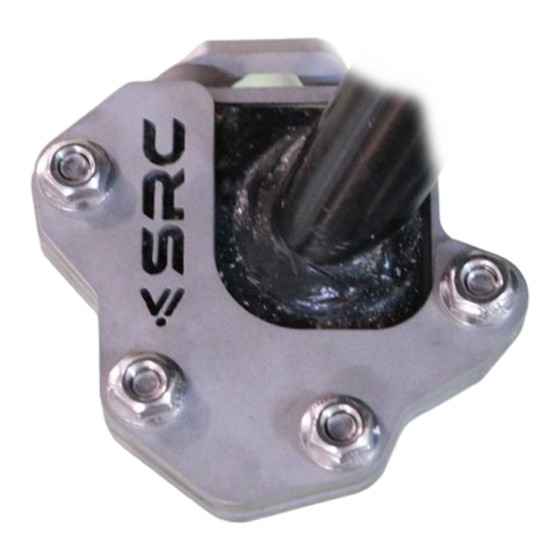
Part Number: Part Description: Large Side Stand – BMW-F800GS-14-01-SL
Installation / Parts List / Bill of Material for Mounting
NO.
Lower Plate
1
Middle Plate
2
3
Upper Plate
4
Nut M6
Countersink Screw M6 X 16
5
SRC Design uses Met ric System of Measu reme nt and all dimensions in Millimeters
* Recommended to use the Torque specified in the table
**Deno tes Usage of Liquid Thread Locker in specified Locations
Copyright By SRC
Design and Specification are subjected to change
Description
Quantity
1
1
1
4
4
Torque * (N-M)
Rema rks **
Use Liquid Thread Locker
9 - 10
Check List
Page 1
Advertisement
Table of Contents

Related Manuals for SRC BMW-F800GS-14-01-SL


Summary of Contents for SRC BMW-F800GS-14-01-SL
- Page 1 Countersink Screw M6 X 16 9 - 10 SRC Design uses Met ric System of Measu reme nt and all dimensions in Millimeters * Recommended to use the Torque specified in the table **Deno tes Usage of Liquid Thread Locker in specified Locations...
- Page 2 MOUNTING DRAWINGS Copyright By SRC Design and Specification are subjected to change Page 2...
- Page 3 Base) for fitment. Step 2: Orient and align the Middle Plate (2), as shown, with its inner walls closely hugging the outer peripheral walls of the Side Stand. Copyright By SRC Design and Specification are subjected to change Page 3...
- Page 4 Orientation and alignment of the plate clusters. The Lower Plate has a Countersunk bore, which flushes with the Countersunk head of the Mounting screws from the bottom, as shown. Copyright By SRC Design and Specification are subjected to change Page 4...
- Page 5 Nuts to torque, as per specification in the BOM table. The final mounted condition of the Large Side Stand will be as shown in the drawing above. Copyright By SRC Design and Specification are subjected to change Page 5...
- Page 6 Vehicle. It is always advised to check loosening of the fasteners after the first 50 kilo meters of ride and at regular intervals. We are showing here the Scope of Supply/ Installation/Parts list & BOM from SRC To the maximum extent possible, our design use the current Mounting/Fitment of the...
Need help?
Do you have a question about the BMW-F800GS-14-01-SL and is the answer not in the manual?
Questions and answers