
Related Manuals for RKI Instruments 35-3001A-08-01


Summary of Contents for RKI Instruments 35-3001A-08-01
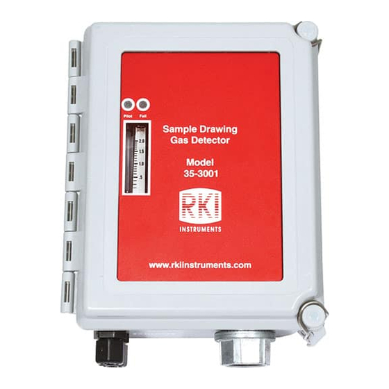
- Page 1 35-3001A-08-XX Sample-Draw Detector Operator’s Manual Part Number: 71-0630 Revision: P1 Released: 1/31/23 RKI Instruments, Inc. www.rkiinstruments.com...
- Page 2 WARNING Read and understand this instruction manual before operating detector. Improper use of the detector could result in bodily harm or death. Periodic calibration and maintenance of the detector is essential for proper operation and correct readings. Please calibrate and maintain this detector regularly! Frequency of calibration depends upon the type of use you have and the sensor types.
- Page 3 Product Warranty RKI Instruments, Inc. warrants gas alarm equipment sold by us to be free from defects in materials, workmanship, and performance for a period of one year from date of shipment from RKI Instruments, Inc. Any parts found defective within that period will be repaired or replaced, at our option, free of charge.
-
Page 4: Table Of Contents
Table of Contents Overview ............6 Specifications . - Page 5 Setting the Zero Reading ........... . 33 Setting the Response Reading.
-
Page 6: Overview
Exhaust Maximum Recommended Inlet/ 50 feet 0 feet Exhaust Line Length for 1/4” O.D. x 1/8” I.D. * RKI Instruments, Inc. does not recommend installing this Tubing tubing size on both the inlet and exhaust. Maximum Inlet Exhaust Recommended Inlet/... - Page 7 Table 1: Specifications Response Time 90% in 30 seconds Combustible Gas: ± 5% of reading or ± 2% of full scale (whichever is greater) Accuracy Carbon Monoxide: ± 5% of reading or ± 5 ppm CO (whichever is greater) WARNING: When using the 35-3001A-08-XX, you must follow the instructions and warnings in this manual to assure proper and safe operation of the 35-3001A-08-XX and to minimize the risk of personal injury.
-
Page 8: Description
Description This section describes the components of the combustible gas/carbon monoxide sample-draw detector. Mounting Foot, 4X Oxygen Flowmeter Circuit Sensor Board Connector IR Amplifier Terminal Charcoal Strip Filter Pump Connector Sensor Flow Pump Control Valve Fail LED CO Sensor Pilot LED L E L P W R / S I G (inside block) -
Page 9: External Components
External Components This section describes the sample-draw detector’s external components. Housing The sample-draw detector’s fiberglass housing is weather- and corrosion-resistant. It is suitable for installation where general purpose equipment is in use. The housing door is hinged on the left side and is secured by two latches on the right side. The flowmeter and status LEDs are visible through a window in the housing door. - Page 10 Internal Components This section describes the sample-draw detector’s internal components (see Figure 1). Figure 2 illustrates how the gas sample moves through the flow system. Pressure Switch Flowmeter Exhaust Carbon Flowmeter PCB Monoxide Restrictor Sensor Sensor Flow Control Valve Inlet Charcoal Filter Sensor...
- Page 11 Oxygen Sensor Terminal Strip The oxygen sensor terminal strip is a two-point terminal strip in the upper right corner of the main circuit board. This terminal strip is not used in this version of the sample-draw detector. Pump Connector The pump connector is the two-point connector below the oxygen terminal strip in the upper right corner of the main circuit board.
-
Page 12: 12 • Internal Components
Pressure Switch The pressure switch is mounted to the back of the flowmeter circuit board. The pressure switch monitors the flow rate of the incoming gas sample. If the flow rate falls below the preset low flow level, the pressure switch causes the Fail LED to turn on and interrupts the signal from the detector. - Page 13 IR Amplifier The IR amplifier converts the electrical output from the IR sensor to a 4 to 20 mA signal that corresponds to the detection range and transmits the signal to a gas monitoring controller. A label on the amplifier indicates the detector drive current. This drive current is factory set. The amplifier is mounted on the top middle edge of the main circuit board.
- Page 14 Test Points The test points are on the left side of the amplifier (see Figure 3). The test points produce a 100 mV to 500 mV output that corresponds to the sample-draw detector’s 4 to 20 mA output. Use the test points and a voltmeter to measure the amplifier’s output during the start-up and calibration procedures.
-
Page 15: Installation
Installation This section describes procedures to mount the sample-draw detector in the monitoring environment and wire the sample-draw detector to a controller. Mounting the Sample-Draw Detector 1. Select the mounting site. Consider the following when you select the mounting site: •... -
Page 16: Connecting The Sample Lines To The Sample-Draw Detector
1/4” O.D. rigid polypropylene, Teflon, or flexible polyurethane tubing may be used. RKI Instruments, Inc. recommends using either 1/4” O.D. x 1/8” I.D. or 1/4” O.D. x 0.170” I.D. tubing based on your length requirements. See “Specifications” on page 6 for maximum tubing lengths based on tubing size. - Page 17 2. Push 1/4” O.D. rigid polypropylene or rigid Teflon sample tubing into the fitting until it stops. Flexible polyurethane tubing may be used with an appropriate insert. RKI Instruments, Inc. recommends using either 1/4” O.D. x 1/8” I.D. or 1/4” O.D. x 0.170” I.D. tubing based on your length requirements.
-
Page 18: Wiring The Sample-Draw Detector To A Controller
Wiring the Sample-Draw Detector to a Controller WARNING: Always verify that the controller is off and that power to the controller is off before you make wiring connections. 1. Turn off the controller. 2. Turn off power to the controller. 3. - Page 19 Not Used on This Version Sensor ZE R O Current 148m A S PA N L EL P W R / S IG White Black Blue (S) White Green Red (+) Black IR Sensor A M P 1 A M P 2 L EL /I R O XY IR Sensor...
-
Page 20: Start Up
Start Up This section describes procedures to start up the sample-draw detector and place the sample-draw detector into normal operation. Introducing Incoming Power 1. Complete the installation procedures described earlier in this manual. 2. Verify that the wiring is correct and secure. Refer to the controller operator’s manual for connections at the controller. -
Page 21: Setting The Zero Reading
Setting the Zero Reading CAUTION: If you suspect the presence of combustible or toxic gas or an abnormal oxygen concentration in the monitoring environment, use the calibration kit and the zero air calibration cylinder to introduce “fresh air” to the sensor and verify an accurate zero setting. -
Page 22: Troubleshooting
5. If the fail condition continues, replace the sensor(s) as described in “Replacing Components of the Sample-Draw Detector” on page 24. 6. If the fail condition continues, contact RKI Instruments, Inc. for further instruction. 22 • Maintenance 35-3001A-08-XX Sample-Draw Detector... - Page 23 4. If you cannot set the correct flow rate, check the sample line for obstructions or kinks. 5. If the calibration/response difficulties continue, replace the sensor as described later in this section. 6. If the calibration/response difficulties continue, contact RKI Instruments, Inc. for further instruction. 35-3001A-08-XX Sample-Draw Detector...
-
Page 24: Replacing Components Of The Sample-Draw Detector
Replacing Components of the Sample-Draw Detector This section includes procedures to replace the IR combustible gas sensor, IR combustible gas amplifier, carbon monoxide sensor, carbon monoxide amplifier, charcoal filter, hydrophobic filter, and particle filter. Replacing the IR Sensor 1. Turn off the controller. 2. - Page 25 6. Remove the old amplifier from the main circuit board. 7. Install the new amplifier in the same orientation as the old amplifier. See Figure 1. 8. Reinstall the screw, lock washer, and flat washer you removed in step 5. 9.
- Page 26 3. Open the housing door of the sample-draw detector. 4. Unscrew the two screws in the upper right and lower left corners of the CO flow block then lift the CO amplifier and sensor off of the flow block. There is a gasket at the bottom of the flow block. Be sure the gasket stays in place. 5.
- Page 27 11. Turn on power to the controller. 12. Turn on the controller and place it into normal operation. 13. Allow the sample-draw detector to warmup for 5 minutes. 14. Calibrate the sample-draw detector as described in “Calibration, CO Sensor” on page 32. Replacing the Charcoal Filter 1.
-
Page 28: Adjusting The Low Flow Setting
Replacing the Particle Filter 1. Turn off the controller. 2. Turn off power to the controller. 3. If the particle filter is installed at the inlet fitting: a. Disconnect the tubing routed to the sampling area, if installed, from the particle filter. b. -
Page 29: Removing The Particle Filter's Tubing Stub, If Necessary
5. Use the sensor flow control valve to set the flow to 1.0 SCFH. 6. Make sure the sample-draw detector’s Fail LED is off. Removing the Particle Filter’s Tubing Stub, if Necessary A short tubing stub comes factory installed in the particle filter. It is used for connecting the particle filter to the inlet fitting. -
Page 30: Calibration Frequency
Ensure that you are using the correct target gas for your sensor. Refer to the following calibration gas requirements: • 35-3001A-08-01 needs to be calibrated with %LEL levels of methane. • 35-3001A-08-02 needs to be calibrated with %LEL levels of the target hydrocarbon gas. -
Page 31: Setting The Zero Reading
5. Connect the voltmeter to the test points on the IR amplifier. Plug the positive lead into the red (+) amplifier test point; plug the negative lead into the black (-) amplifier test point labeled. 6. Use the following formula to determine the correct test points output for the calibrating sample. -
Page 32: Returning To Normal Operation
Returning to Normal Operation 1. Wait approximately one minute to allow the combustible gas reading to stabilize. 2. Remove the voltmeter leads from the amplifier test points. 3. Close the housing door. 4. Follow the instructions in the controller’s operator’s manual to exit the calibration mode. 5. - Page 33 Setting the Zero Reading 1. Connect the sample tubing from the demand flow regulator to the sample-draw detector’s inlet fitting. This step is not necessary if you verified a fresh air environment earlier in this procedure. 2. Allow the sample draw detector to draw sample for one minute. 3.
- Page 34 Parts List Table 4 lists replacement parts and accessories for the sample-draw detector. Table 4: Parts List Part Number Description 06-1248RK Sample tubing, 3/16” ID x 5/16” OD, specify length 06-1248RK-03 Sample tubing, 3/16” ID x 5/16” OD, 3 feet (for calibration kit) 07-0053RK Gasket for carbon monoxide flow block 07-0110RK...
- Page 35 Table 4: Parts List Part Number Description 81-0076RK-01 Zero air calibration cylinder, 34 liter steel 81-0076RK-03 Zero air calibration cylinder, 103 liter 81-1054RK Regulator, demand flow, for 34 liter aluminum, 58 liter, and 103 liter calibration cylinders (cylinders with internal threads) 81-1055RK Regulator, demand flow, for 17 liter and 34 liter steel calibration cylinders (cylinders with external threads)
Need help?
Do you have a question about the 35-3001A-08-01 and is the answer not in the manual?
Questions and answers