
Related Manuals for RKI Instruments 35-3001A-08


Summary of Contents for RKI Instruments 35-3001A-08
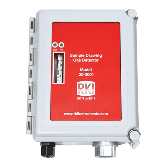
- Page 1 35-3001A-08 Combustible Gas Sample-Draw Detector Operator’s Manual Part Number: 71-0589 Revision: P1 Released: 2/17/22 www.rkiinstruments.com...
- Page 2 Typical calibration frequencies for most applications are between 3 and 6 months, but can be required more often or less often based on your usage. 35-3001A-08 Combustible Gas Sample-Draw Detector Operator’s Manual...
- Page 3 Product Warranty RKI Instruments, Inc. warrants gas alarm equipment sold by us to be free from defects in materials, workmanship, and performance for a period of one year from date of shipment from RKI Instruments, Inc. Any parts found defective within that period will be repaired or replaced, at our option, free of charge.
-
Page 4: Table Of Contents
Parts List ..............32 35-3001A-08 Combustible Gas Sample-Draw Detector Operator’s Manual... -
Page 5: Overview
Overview This operator’s manual describes the 35-3001A-08 combustible gas/carbon monoxide sample- draw detector. This manual also describes how to install, start up, maintain, and calibrate the sample-draw detector when using it with a gas monitoring controller. A parts list at the end of this manual lists replacement parts and accessories for the sample-draw detector. - Page 6 WARNING: When using the 35-3001A-08, you must follow the instructions and warnings in this manual to assure proper and safe operation of the 35-3001A-08 and to minimize the risk of personal injury. Be sure to maintain and periodically calibrate the 35-3001A- 08 as described in this manual.
-
Page 7: Description
Description This section describes the components of the combustible gas/carbon monoxide sample-draw detector. Mounting Foot , 4X LEL Amplifier Oxygen Sensor Flowmet er C ircuit Terminal Board C onnector Strip Sensor Flow Pump C onnector S en so r Control Valve C u rr en t 14 8m A Pump... -
Page 8: External Components
External Components This section describes the sample-draw detector’s external components. Housing The sample-draw detector’s fiberglass housing is weather- and corrosion-resistant. It is suitable for installation where general purpose equipment is in use. The housing door is hinged on the left side and is secured by two latches on the right side. The flowmeter and status LEDs are visible through a window in the housing door. -
Page 9: Internal Components
Internal Components This section describes the sample-draw detector’s internal components (see Figure 1). Figure 2 illustrates how the gas sample moves through the flow system. Pressure Switch Flowmeter Exhaust Carbon Flowmeter PCB Monoxide Restrictor Sensor Sensor Flow Control Valve Inlet Flow Baffle Sensor... - Page 10 Pump Connector The pump connector is the two-point connector below the oxygen terminal strip in the upper right corner of the main circuit board. Use the pump connector to connect the pump to the main circuit board. NOTE: The pump is factory-wired to the main circuit board. See “Installation” on page 14 for all wiring procedures related to the sample-draw detector.
- Page 11 Pump Reset Switch The pump reset switch is located to the left of the status LEDs. When a low flow condition occurs, the pump will be shut off. To reset the low flow condition and start the pump again, press and hold the pump reset switch for about 2 seconds, then release. Hydrophobic Filter The hydrophobic filter is located toward the bottom left of the main circuit board.
- Page 12 LEL Amplifier The combustible gas amplifier converts the electrical output from the LEL sensor to a 4 to 20 mA signal that corresponds to the detection range and transmits the signal to a gas monitoring controller. A label on the amplifier indicates the detector drive current. This drive current is factory set.
- Page 13 Test Points The test points are on the left side of the amplifier (see Figure 3). The test points produce a 100 mV to 500 mV output that corresponds to the sample-draw detector’s 4 to 20 mA output. Use the test points and a voltmeter to measure the amplifier’s output during the start-up and calibration procedures.
-
Page 14: Installation
Installation This section describes procedures to mount the sample-draw detector in the monitoring environment and wire the sample-draw detector to a controller. Mounting the Sample-Draw Detector 1. Select the mounting site. Consider the following when you select the mounting site: •... -
Page 15: Connecting The Sample Lines To The Sample-Draw Detector
1/4” O.D. rigid polypropylene, Teflon, or flexible polyurethane tubing may be used. RKI Instruments, Inc. recommends using either 1/4” O.D. x 1/8” I.D. or 1/4” O.D. x 0.170” I.D. tubing based on your length requirements. See “Specifications” on page 5 for maximum tubing lengths based on tubing size. - Page 16 Installing the Inlet Line without Particle Filter Connected to the Inlet Fitting 1. Loosen the nut on the inlet fitting until 3 threads are visible. 2. Push 1/4” O.D. rigid polypropylene or rigid Teflon sample tubing into the fitting until it stops.
-
Page 17: Wiring The Sample-Draw Detector To A Controller
Wiring the Sample-Draw Detector to a Controller WARNING: Always verify that the controller is off and that power to the controller is off before you make wiring connections. 1. Turn off the controller. 2. Turn off power to the controller. 3. - Page 18 8. Connect the wires to the applicable detector/transmitter terminal strip at the controller as shown in Figure 6. Refer to the controller operator’s manual and the controller detector head specification sheet for the 35-3001A-08 for detector/terminal strip connections specific to the controller.
-
Page 19: Start Up
9. If shielded cable is used, connect the cable’s drain wire to an available chassis (earth) ground at the controller. RKI controllers typically have a ground stud that can be used to ground the cable’s drain wire. Start Up This section describes procedures to start up the sample-draw detector and place the sample- draw detector into normal operation. -
Page 20: Setting The Zero Reading
CAUTION: Allow the sample-draw detector to warm up for 5 minutes before you continue with the next section, “Setting the Zero Reading.” Setting the Zero Reading CAUTION: If you suspect the presence of combustible or toxic gas or an abnormal oxygen concentration in the monitoring environment, use the calibration kit and the zero air calibration cylinder to introduce “fresh air”... -
Page 21: Troubleshooting
5. If the fail condition continues, replace the sensor(s) as described in “Replacing Components of the Sample-Draw Detector” on page 22. 6. If the fail condition continues, contact RKI Instruments, Inc. for further instruction. Slow or No Response/Difficult or Unable to Calibrate Symptoms •... -
Page 22: Replacing Components Of The Sample-Draw Detector
4. If you cannot set the correct flow rate, check the sample line for obstructions or kinks. 5. If the calibration/response difficulties continue, replace the sensor as described later in this section. 6. If the calibration/response difficulties continue, contact RKI Instruments, Inc. for further instruction. Replacing Components of the Sample-Draw Detector This section includes procedures to replace the LEL sensor, LEL amplifier, carbon monoxide sensor, carbon monoxide amplifier, hydrophobic filter, and particle filter. - Page 23 CAUTION: Allow the replacement sensor to warm up for 5 minutes before you continue. 11. Calibrate the replacement sensor as described in “Calibration, LEL Sensor” on page 28. Replacing the LEL Amplifier 1. Turn off the controller. 2. Turn off power to the controller. 3.
- Page 24 NOTE: When the sample-draw detector is first powered up with a new amplifier, the initial output may be either high or below zero depending on the setting of the zero pot. Be sure to make arrangements so that this does not cause unwanted alarms. 10.
- Page 25 There is a gasket at the bottom of the flow block. Be sure the gasket stays in place. 6. Disconnect the sensor from the CO amplifier. 7. Plug the CO sensor into the new CO amplifier. 8. Place the sensor and amplifier in the CO sensor cavity. 9.
-
Page 26: Adjusting The Low Flow Setting
b) Disconnect the particle filter from the tubing stub. c) Install the new particle filter onto the tubing stub. Be sure the arrow on the particle filter is pointing toward the inlet fitting. d) Reinstall the tubing routed to the sampling area. 4. -
Page 27: Removing The Particle Filter's Tubing Stub, If Necessary
Removing the Particle Filter’s Tubing Stub, if Necessary A short tubing stub comes factory installed in the particle filter. It is used for connecting the particle filter to the inlet fitting. If you have installed the particle filter and no longer want it installed, you will need to remove the particle filter’s tubing stub from the inlet fitting and replace it with tubing. -
Page 28: Calibration Frequency
Calibration Frequency Although there is no particular calibration frequency that is correct for all applications, a calibration frequency of every 3 months is adequate for most sample draw detector applications. Unless experience in a particular application dictates otherwise, RKI Instruments, Inc. recommends a calibration frequency of every 3 months for the CO detector and LEL detector. -
Page 29: Setting The Zero Reading
Setting the Zero Reading 1. Connect the sample tubing from the demand flow regulator to the sample-draw detector’s inlet line. This step is not necessary if you verified a fresh air environment earlier in this procedure. 2. Allow the sample-draw detector to draw sample for one minute. 3. -
Page 30: Calibration, Co Sensor
Calibration, CO Sensor This section describes how to calibrate the CO sensor in the sample-draw detector. It includes procedures to prepare for calibration, set the zero reading, set the response reading, and return to normal operation. NOTE: Calibrating the sample draw detector may cause alarms. Be sure to put the controller into its calibration program or disable external alarms before continuing. -
Page 31: Setting The Response Reading
4. If necessary, use a small flat-blade screwdriver to adjust the zero potentiometer until the voltmeter reading is 100 mV (± 2 mV). If you used a zero air calibration cylinder to set the zero reading, proceed to step 5. If you verified a fresh air environment, proceed to the next section, Setting the Response Reading. -
Page 32: Parts List
Pump 33-0165RK Hydrophobic filter 33-0167RK Particle filter 71-0589 Operator’s Manual, 35-3001A-08 Sample-Draw Detector 81-0002RK-01 Calibration cylinder, 50% LEL hydrogen in air, 34 liter steel 81-0002RK-03 Calibration cylinder, 50% LEL hydrogen in air, 103 liter 81-0007RK-01 Calibration cylinder, 50% LEL hexane in air, 34 liter steel...
Need help?
Do you have a question about the 35-3001A-08 and is the answer not in the manual?
Questions and answers