Advertisement
Quick Links
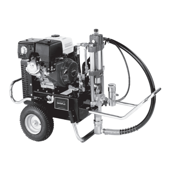
Hydra M
Gas Powered Airless Sprayer
Model Numbers:
Hydra M 2000™
Hydra M 4000™
Hydra Pro Super™
Printed in the U.S.A.
SPEEFLO
™
/ Hydra Pro Super
433-860
433-861 (55 gal.)
433-800 (roofer model)
433-801 (painter model)
433-802 (55 gal.)
433-810
Owner's Manual
For professional use only
Do not use this equipment
before reading this manual!
NOTE: This manual contains important
warnings and instructions. Please read
and retain for reference.
© Titan Tool Inc. All Rights Reserved. Form No. 0528925L
0317
™
Advertisement

Related Manuals for Titan SPEEFLO Hydra M 2000


Summary of Contents for Titan SPEEFLO Hydra M 2000
- Page 1 Hydra M 4000™ 433-800 (roofer model) warnings and instructions. Please read 433-801 (painter model) and retain for reference. 433-802 (55 gal.) Hydra Pro Super™ 433-810 © Titan Tool Inc. All Rights Reserved. Form No. 0528925L 0317 Printed in the U.S.A.
-
Page 2: Hydra M 2000™ Major Components
Hydra M 2000™ Major Components © Titan Tool Inc. All rights reserved. - Page 3 840-207 Outlet assembly, 1” 103-106 Bleed line assembly (1) 945-600 Bleed valve (1) 103-818 Siphon hose assembly 1 1/2” x 6’ 219-650 Adj. drum mount assembly All models are equipped with electric starter. © Titan Tool Inc. All rights reserved.
-
Page 4: Hydra M 4000™ Major Components
Hydra M 4000™ Major Components © Titan Tool Inc. All rights reserved. - Page 5 Siphon hose, 1 1/4” x 4’ 103-807 Siphon hose, 1” x 4’ 840-209 Relief valve w/bleed line 219-650 Adj. drum mount assembly Hydra Pro Super™ is not illustratred. All models are equipped with electric starter. © Titan Tool Inc. All rights reserved.
- Page 6 Hydra M™ and Hydra Pro Super™ Engine Drive & Hydraulic System 61/62 33 34 35 36 © Titan Tool Inc. All rights reserved.
- Page 7 Hydr. Hose set 191-665 Nipple 432-711 Pressure hose 432-685 Return hose For Hydra M 4000™ and Hydra Pro Super™ ITEM PART DESCRIPTION QTY. 432-681 Hydraulic hose set 432-715 Pressure hose 432-688 Return hose © Titan Tool Inc. All rights reserved.
- Page 8 Hydra M™ & Hydra Pro Super™ Tank Assembly and Mobil Kit © Titan Tool Inc. All rights reserved.
- Page 9 Ground lug 858-628 Screw 432-609 O-ring 434-621 Bushing 227-033 Pipe plug 141-007 O-ring 434-682 Pressure control assembly 185-983 Cotter key (1) 434-671 Shaft, pressure control (1) 866-601 Nut, jam (2) 970-013 Knob (1) © Titan Tool Inc. All rights reserved.
- Page 10 Hydra M™ 2000 and Hydra M™ 4000 441-576 Hydraulic Motor © Titan Tool Inc. All rights reserved.
- Page 11 445-237 Ring, wear 441-025 Wiper, piston tube 441-152 O-ring 432-640 Elbow 441-015 Stanchion 441-017 441-916 Head, cylinder 432-611 O-ring set 191-668 Adapter 441-789 Tube 194-114 O-ring 432-729 Elbow 194-113 O-ring 632-611 O-ring set © Titan Tool Inc. All rights reserved.
- Page 12 Hydra M™ & Hydra Pro Super™ 441-575 Hydraulic Motor Service Instructions © Titan Tool Inc. All rights reserved.
- Page 13 IMPORTANT: Use of non-Titan manufactured service parts 10. Place new O-ring (11) and new back-up ring (10) on cylinder may void warranty. This motor contains hydraulic fluid. Take head (15) and lower cylinder head on to cylinder (28), shifter precautions to protect the immediate area from oil damage upon actuator assembly (19) and upper stanchions (14) with disassembly.
- Page 14 Nut, spacer 870-401 Nut, stanchion 870-004 Washer 441-013 Stanchion 441-010 Stanchion, long 441-968 Stirrup 870-021 Nut, lock 441-959 Rod, connecting 441-007 Nut, coupling 180-974 Conrod extension (not illustrated) * Not included in this assembly © Titan Tool Inc. All rights reserved.
- Page 15 PART repairs. DESCRIPTION QTY. Packing life will be extended by the use of Piston Lube, Titan part 314-030 Packing set, upper # 314-480 permanent solvent. Fill to 1/4” level in pump block (2). Do not use oil or thinners as lubricant. Use Piston Lube for upper...
- Page 16 870-006 Spacer 140-016 Stanchion 441-010 Stanchion, 55 gal 245-109 Roll pin 442-959 Rod, connecting 441-959 Rod, connecting 441-007 Nut, coupling 180-972 Ext., connecting rod 441-968 Stirrup 870-021 * Not included in this assembly © Titan Tool Inc. All rights reserved.
-
Page 17: Disassembly Procedure
O-ring seals perform on one stroke or the other. The use of Titan Piston Lube, part # sealing function without excessive tightening. Full 314-480 is recommended as an upper packing lubricant. DO NOT thread engagement is su cient. - Page 18 Displacement Volume / Displacement Volume / 40 Cycles / Motor Motor Pump Rod Area Stroke 80 Strokes Selection ratio LITER GAL. LITER 1.38 8.90 10.2 5.55 90.9 0.091 1.92 7272 7.27 441 Series © Titan Tool Inc. All rights reserved.
- Page 19 The foot valve on one stroke or another. The use of Titan Piston Lube Part # (16) may be rotated back up to 3/4 turn from full 314-480 is recommended as an upper packing lubricant.
- Page 20 ITEM 840- 840- PART NO. DESCRIPTION 200-556 Swivel adapter, 1” 138-037 Swivel adapter, 3/4” 813-009 Cross 817-004 929-063 Bushing 929-075 Bushing 929-076 Bushing 945-600 Valve, bleed 103-106 Bleed line assembly 210-039 Plug, pipe © Titan Tool Inc. All rights reserved.
- Page 21 O-ring (5) may require replacement. If there has been leakage from the IMPORTANT: All non-moving threads must be assembled with valve stem, the PTFE O-ring should be replaced. Loctite sealant, Titan part # 426-051. © Titan Tool Inc. All rights reserved.
- Page 22 IMPORTANT: The valve stem stop (6) must be unthreaded from the valve stem (3) with a socket screwdriver, then the valve stem can be threaded out of the valve body. IMPORTANT: All non-moving threads must be assembled with Loctite sealant, Titan part # 426-051. 103-807 Siphon Valve Assembly...
- Page 23 PTFE The 920 Series Filter Elements lter from the inside out. Be certain to clean the screen element thoroughly on the inside. Soak in solvent to loosen hardened paint, etc. or replace. © Titan Tool Inc. All rights reserved.
- Page 24 4 GUN 3/8” 1 GUN DESCRIPTION ADD ON ADD ON 1/4” 3/8” 970-100 Manifold 940-553 Valve, ball 941-555 Valve, ball 814-002 Nipple, hex 814-004 Nipple, hex 227-006 Nipple, hex 808-555 Nipple, hex 227-033 Plug, pipe © Titan Tool Inc. All rights reserved.
-
Page 25: Key Accessories And Service Kits
Key Accessories and Service Kits These items may be purchased separately from your local Titan distributor. Part No. Description 103-818 Siphon hose assembly with CamLock assembly, 1 1/2” x 6’ 103-807 Siphon hose assembly with rock catcher 1” x 4’... -
Page 26: Warranty
Warranty warranty is free from defects in material and workmanship. With the exception of any special, limited, or extended warranty published by Titan, Titan’s obligation under this warranty is limited to replacing or repairing without charge those parts which, to Titan’s reasonable satisfaction, are shown to be defective within twelve (12) months after sale to the End User.
Need help?
Do you have a question about the SPEEFLO Hydra M 2000 and is the answer not in the manual?
Questions and answers