
Related Manuals for Redexim MULTIVATOR 1800


Summary of Contents for Redexim MULTIVATOR 1800
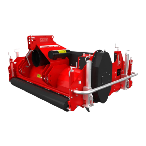
- Page 1 User manual MULTIVATOR 1800 Translation of the original user manual 2305 English 915.120.210 EN Kwekerijweg 8 | 3709JA | Zeist | The Netherlands | T: +31 (0)306 933 227 redexim@redexim.com www.redexim.com...
- Page 2 EU – DECLARATION OF CONFORMITY Redexim Handel- en Exploitatie Maatschappij B.V. Kwekerijweg 8 3709 JA Zeist, The Netherlands declare that this “EU - DECLARATION OF CONFORMITY” is issued under our sole responsibility and belongs to the following product: CARRIER WITH MACHINE NUMBER AS INDICATED ON THE MACHINE AND IN THIS MANUAL,...
- Page 3 UK – DECLARATION OF CONFORMITY Redexim Handel- en Exploitatie Maatschappij B.V. Kwekerijweg 8 3709 JA Zeist, The Netherlands declare that this “UK - DECLARATION OF CONFORMITY” is issued under our sole responsibility and belongs to the following product: CARRIER WITH MACHINE NUMBER AS INDICATED ON THE MACHINE AND IN THIS MANUAL, to which this declaration refers, complies with stipulation of: S.I.
-
Page 4: Foreword
THIS MACHINE IS COVERED BY A WARRANTY AGAINST DEFECTS IN MATERIALS. THIS WARRANTY IS VALID FOR A PERIOD OF 12 MONTHS FROM THE DATE OF PURCHASE. REDEXIM WARRANTIES ARE SUBJECT TO THE ‘GENERAL CONDITIONS FOR SUPPLY OF PLANT AND MACHINERY FOR EXPORT, NUMBER 188’, PUBLISHED UNDER THE AUSPICES OR THE UNITED NATIONS ECONOMIC COMMISSION FOR EUROPE. -
Page 5: Table Of Contents
TABLE OF CONTENTS FOREWORD ..........................4 WARRANTY CONDITIONS ....................4 REGISTRATION CARD ......................4 SAFETY INSTRUCTIONS ..................6 1.1. User's obligations ......................6 1.2. Maintenance, repair and adjustment ................7 1.3. Use of the machine ......................7 TECHNICAL DATA ....................8 GENERAL DESCRIPTION ..................8 SAFETY STICKERS....................9 FIRST INSTALLATION .................... -
Page 6: Safety Instructions
1. SAFETY INSTRUCTIONS This machine is designed for safe use. Safe use is only possible if the safety instructions described in this manual are fully adhered to. Read and understand the manual before you start using this machine. Failure to use the machine as described in the manual may result in personal injury and/or damage to the machine. -
Page 7: Maintenance, Repair And Adjustment
Use, maintenance or repair of the machine by incompetent persons may result in a risk of injury to both the user and third parties. This must be prevented! Use only original Redexim replacement parts for maintenance or repair, in the interest of the safety of the machine and user. -
Page 8: Technical Data
2. TECHNICAL DATA Model 1800 1.80 m (70.9”) Working width Max 140 mm (5.5”) Working depth PTO speed 540 rpm Machine weight 1050 kg (2315 lbs)( base machine) 1225 kg (2700 lbs) (base machine plus hydraulic rearbrush) Number of blades 10 mm (0.4”) Blade thickness Working speed... -
Page 9: Safety Stickers
4. SAFETY STICKERS Safety stickers are present on both sides of the machine. These safety stickers must always be clearly visible and legible and, if damaged, must be replaced (Fig. 1) Fig. 1 During maintenance, adjustment and repairs, the engine of the towing vehicle and the PTO must ALWAYS be switched off. -
Page 10: First Installation
5. FIRST INSTALLATION Ensure that the cable/crane/lift can lift at least 2x the weight of the machine. For the weight, see chapter 2 ‘Technical data’. Carry out this work on a flat, firm surface with sufficient free space. The machine must be prepared for use as follows: (Fig. 2 and 3) 1. -
Page 11: The Pto Shaft
6. THE PTO SHAFT The PTO shaft is a very important part. It provides the drive from the tractor to the machine. The PTO shaft, when properly maintained and installed, ensures safe operation of the machine. The PTO shaft has its own CE certification and manual. These are found with the PTO shaft. For specific adjustments, see the details given on the PTO page in the parts manual. -
Page 12: Use Of The Pto Shaft
4. Both the ends of the yokes and the halves of the safety shield must be shortened: (B-A) + 125 mm (4.9”). 5. Deburr all the parts and reassemble. Apply grease during assembly. 6. Fit the PTO shaft with the slip clutch on the machine end. 7. -
Page 13: Connecting The Machine
7.1. Connecting the machine Before connecting, check the machine as follows: Check that the machine is not damaged and that it can be safely connected and used. Check for loose parts and secure them firmly again. Check that all safety stickers are present on the machine and that they are undamaged and clearly legible. -
Page 14: Disconnecting The Machine
7.2. Disconnecting the machine The machine must be disconnected as follows: (Fig. 7) Drive to the location where you want to disconnect the machine. Lift the machine high enough so you can lower the support legs. Lower the support legs. Make sure the storage area has a stable surface and that the machine cannot sink in. -
Page 15: Putting The Machine Into Operation
Fig. 8 9. PUTTING THE MACHINE INTO OPERATION 9.1. Safety Check the following before using the machine: 1. Are there loose objects in the field? Remove them first. 2. Are there inclines? The maximum incline on which work may be performed with this machine is 20 degrees. -
Page 16: Working Speed
9.2. Working speed The maximum working speed of the machine depends on soil conditions, working depth, gearbox settings and the desired result. The maximum working speed is limited to 3 km/h (1.9 mph). Faster speeds are not recommended due to excessive wear and potential damage to the machine. If hard objects are to be expected, the working speed must be reduced. -
Page 17: Technical Information
TECHNICAL INFORMATION Generally speaking, the Multivator is not a complicated machine. A number of technical matters will be explained. If you still have questions thereafter, contact your dealer, who will be happy to assist you. 10.1. Adjusting the working depth of the rotor The working depth can be adjusted by adjusting the support rollers, as follows: (Fig. -
Page 18: Adjusting The Working Depth Of The Blade Roller
10.2. Adjusting the working depth of the blade roller The cutting roller depth can be adjusted independently of the rotor, but the cutting roller depth depends on how the support rollers are set. If these are adjusted, the cutting roller depth will change too. -
Page 19: Opening Machine Access Hatches
10.3. Opening machine access hatches The Multivator is fitted with access hatches for access to the inside of the machine, for cleaning and replacing blades, etc. These hatches must be opened as shown below (fig. 11): !! Shut off the tractor’s engine and disengage the PTO before stepping out!! !! Make sure the tractor and machine cannot move unintentionally!! 1. -
Page 20: Options
11. OPTIONS The following options are available for the Multivator: 11.1. Hydraulic rear brush A hydraulic rear roller is available for aerating the loosened soil for faster drying. Part number: 215,180,002 The set includes all necessary materials. See parts manual for the contents. The rear brush is hydraulically driven and hydraulically liftable and is mounted on the inside of the rear roller for depth adjustment. -
Page 21: Pre-Cutting Roller
11.2. Pre-cutting roller In some circumstances it is better to pre-cut the turf prior to slicing the trenches; a pre-cutting roller is available for this purpose. Part number: 215,180,204 This pre-cutting roller replaces the normal front roller; a matching scraper is supplied in the set. See parts manual for the contents. -
Page 22: Maintenance
MAINTENANCE 12.1. Maintenance schedule Time schedule Check point Work activities Before each use Check for loose parts. Secure the loose parts in the proper manner. General inspection Connect the machine to the tractor and let the machine run for five minutes. Look and listen for abnormal movements and noises. -
Page 23: Fitting Or Replacing The Blades
12.2. Fitting or replacing the blades The machine comes new with a set of unmounted blades. To fit or replace the blades, proceed as follows: (Fig. 14) Fig. 14 1. Disconnect the machine from the tractor as described in section 7.2. 2. -
Page 24: Cleaning
12.3. Cleaning When using a pressure washer to clean the machine, observe the following rules: • Do not use aggressive cleaning products that may damage the machine. • Maximum water pressure: 70 bar (1015 psi) • Maximum water temperature: 50 °C (122 °F) •... -
Page 25: Replacing Grease In Drive Unit
12.5. Replacing grease in drive unit 1. Place the machine on the support legs on a flat, stable surface. Grease level Above rotor shaft Fig. 16 !! Shut off the tractor’s engine and PTO before stepping out!! !! Make sure the tractor and machine cannot move unintentionally!! !! Never crawl under the machine!! 2. -
Page 26: Tensioning Chain
12.6. Tensioning chain Wear causes the chain to stretch, and therefore it must be re-tensioned. Preferably, do this in combination with refilling/replacing the grease in the drive unit (section 12.5). Proceed as follows: !! Never crawl under the machine!! Check the grease level in the drive unit and, if necessary, remove some of the grease prior to tensioning. -
Page 27: Troubleshooting
TROUBLESHOOTING Problem Possible cause Solution Machine vibrates Obstacles in the ground. Lift the machine to above the depth at which they are located and, after driving further, lower it to the desired working depth again. Remove the obstacle. Obstacle between the blades. Twist the top link until the machine is Angles of PTO universal joints horizontal. - Page 28 Problem Possible cause Solution Rotor shaft does not Gearbox output shaft does not turn. Repair or replace gearbox. turn with PTO engaged. Replace chain. Chain broken. Check entire driveline and replace Gears slipping on shafts. parts as necessary. Check entire driveline and replace Other cause.
Need help?
Do you have a question about the MULTIVATOR 1800 and is the answer not in the manual?
Questions and answers