Advertisement
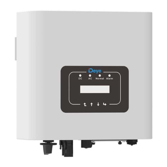
Grid-connected PV Inverter
SUN-�K-G��P�-EU-AM�
SUN-1.5K-G04P1-EU-AM1
SUN-�K-G��P�-EU-AM�
SUN-�K-G��P�-EU-AM�
SUN-�K-G��P�-EU-AM�
User Manual
The manual mainly describes the product information
same to series SUN-(1-4)K-G04P1
SUN-1K-G04-P
SUN-2K-G04-P
SUN-3K-G04-P
SUN-4K-G04-P
SUN-1.5K-G04-P
SUN2.5K-G04-P
SUN-3.6K-G04-P
R
SUN-�.�K-G��P�-EU-AM�
SUN-�.�K-G��P�-EU-AM�
SUN-�.�K-G��P�-EU-AM�
Advertisement
Table of Contents


Need help?
Do you have a question about the SUN-1K-G04P1-EU-AM1 and is the answer not in the manual?
Questions and answers