Table of Contents
Advertisement
Quick Links
Photovoltaic Grid-connected
Microinverter (Built-in WIFI-G3)
Installation/User Manual
SUN300G3-EU-230, SUN500G3-EU-230, SUN600G3-EU-230, SUN800G3-EU-230,
SUN1000G3-EU-230, SUN1300G3-EU-230, SUN1600G3-EU-230,
SUN1800G3-EU-230, SUN2000G3-EU-230
Global Tech China Ltd, 3 Floor, Wai Yip Industrial Building.171 Wai Yip Street,
Kwun Tong, Kowloon, Hong Kong.
Tel: +852 2884 4318 Fax: +8522884 4816
www.sunsynk.com / sales@globaltech-china.com / www.globaltechhk.com
Version 1.2 (12/08/2020)
Advertisement
Table of Contents
Troubleshooting

Related Manuals for SunSynk SUN300G3-EU-230

Summary of Contents for SunSynk SUN300G3-EU-230
- Page 1 Photovoltaic Grid-connected Microinverter (Built-in WIFI-G3) Installation/User Manual SUN300G3-EU-230, SUN500G3-EU-230, SUN600G3-EU-230, SUN800G3-EU-230, SUN1000G3-EU-230, SUN1300G3-EU-230, SUN1600G3-EU-230, SUN1800G3-EU-230, SUN2000G3-EU-230 Global Tech China Ltd, 3 Floor, Wai Yip Industrial Building.171 Wai Yip Street, Kwun Tong, Kowloon, Hong Kong. Tel: +852 2884 4318 Fax: +8522884 4816 www.sunsynk.com / sales@globaltech-china.com / www.globaltechhk.com...
-
Page 2: Table Of Contents
INDEX 1. IMPORTANT SAFETY INSTRUCTIONS ....................4 1.1. RADIO INTERFERENCE STATEMENT ......................5 1.2. SYMBOLS..............................5 2. MICROINVERTER SYSTEM INTRODUCTION ..................6 2.1. MICROINVERTERS MAXIMIZE PV ENERGY PRODUCTION ................7 2.2. MORE RELIABLE THAN CENTRALIZED OR STRING INVERTERS ..............7 2.3. INSTALLATION - SIMPLICITY ........................8 3. MICROINVERTER INTRODUCTION ......................8 4. - Page 3 LIST OF FIGURES 1 - 300G3/500G3/600G3/800G3/1000G3 ..............6 IGURE MODELS 2 - 1300G3/1600G3/1800G3/2000G3..................7 IGURE 3 - I ..............9 IGURE NSTALLING THE BRANCH CIRCUIT JUNCTION BOX 4 - 300G3/500G3 (1MPPT) 600G3/800G3/1000G3 (2MPPT) ......10 IGURE MOUNTING 5 - 1300G3/1600G3/2000G3 (4MPPT) .
-
Page 4: Important Safety Instructions
DC connections. When disconnecting, disconnect the AC by opening the branch circuit breaker first but maintain the protective earthing conductor in the branch circuit breaker connect to the inverter, then disconnect the DC inputs. Website: www.sunsynk.com E-mail: sales@globaltech-china.com... -
Page 5: Radio Interference Statement
Consult the dealer or an experienced radio / TV technician for help. Changes or modifications not expressly approved by the party responsible for compliance may void the user's authority to operate the equipment. 1.2. SYMBOLS Website: www.sunsynk.com E-mail: sales@globaltech-china.com... -
Page 6: Microinverter System Introduction
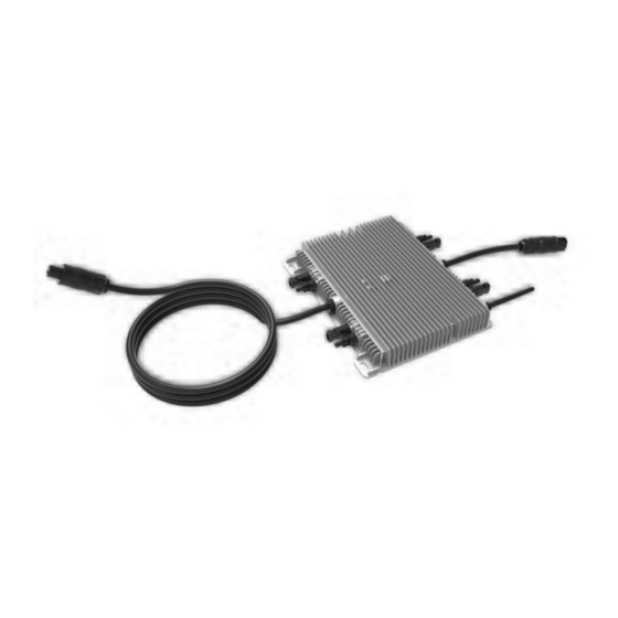
2. MICROINVERTER SYSTEM INTRODUCTION The Microinverter is used in utility-interactive grid-tied applications and it is comprised of two key elements: the Microinverter and the router. Figure 1 - 300G3/500G3/600G3/800G3/1000G3 models. Website: www.sunsynk.com E-mail: sales@globaltech-china.com... -
Page 7: Microinverters Maximize Pv Energy Production
The distributed Microinverter system ensures that no single point of system failure exists across the PV system. Microinverters are designed to operate at full power at ambient outdoor temperatures of up to 149℉ (65℃). The inverter housing is designed for outdoor installation and complies with the IP65 environmental enclosure rating Website: www.sunsynk.com E-mail: sales@globaltech-china.com... -
Page 8: Installation - Simplicity
For more information, please see the Technical Data page (P17~20) of this manual. Model Number AC Grid Max. # Per Branch SUN300G3-EU-230 50/60Hz, 230 V 17 for 45A breaker SUN500G3-EU-230 50/60Hz, 230 V... -
Page 9: Additional Installation Components
Continuous grounding conductor and grounding washers ◼ A Phillips screwdriver ◼ A torque wrench 5. INSTALLATION PROCEDURES Step 1 – Install the AC branch circuit junction box Figure 3 - Installing the AC branch circuit junction box. Website: www.sunsynk.com E-mail: sales@globaltech-china.com... - Page 10 Mark the location of the Microinverter on the rack, with respect to the PV module junction box or any other obstructions. b) Mount one Microinverter at each of these locations using hardware recommended by your module racking vendor. Figure 4 - 300G3/500G3 (1MPPT) and 600G3/800G3/1000G3 (2MPPT) mounting. Figure 5 - 1300G3/1600G3/2000G3 (4MPPT) mounting. Website: www.sunsynk.com E-mail: sales@globaltech-china.com...
- Page 11 Check the Microinverter technical data in Page 5 for the maximum allowable number of Microinverters on each AC branch circuit. b) Plug the male AC connector of the Microinverter into the female connector to get it connected.AC connector interface as follows. Website: www.sunsynk.com E-mail: sales@globaltech-china.com...
- Page 12 Step 4 – Install an AC cable protective end cap at the end of the AC cable Figure 9 - Installing AC protective end cap. Step 5 – Connect the microinverter to the PV modules Figure 10 - Connecting the microinverter to the solar modules. Website: www.sunsynk.com E-mail: sales@globaltech-china.com...
-
Page 13: Microinverter System Operating Instructions
One minute after DC power is first applied to the Microinverter, one short red blink indicates a successful microinverter startup sequence, be equal or greater than two short red blinks after DC power is first applied to the microinverter indicate a failure during microinverter setup. Website: www.sunsynk.com E-mail: sales@globaltech-china.com... -
Page 14: Troubleshooting A Non-Operating Microinveter
2. Check the connection to the utility grid. Disconnect AC firstly, then disconnect DC and make sure the utility grid voltage can be measured at AC connector. Never disconnect the DC wires while the Microinverter is producing power. Re-connect the DC module connectors and watch for three short LED flashes. Website: www.sunsynk.com E-mail: sales@globaltech-china.com... -
Page 15: Replacement
You must match the DC operating voltage range of the PV module with the allowable input voltage range of the Microinverter. ◼ The maximum open-circuit voltage of the PV module must not exceed the specified maximum input voltage of the inverter. Website: www.sunsynk.com E-mail: sales@globaltech-china.com... - Page 16 300G3/500G3/600G3 Specification: Website: www.sunsynk.com E-mail: sales@globaltech-china.com...
- Page 17 800G3/1000G3 Specification: Website: www.sunsynk.com E-mail: sales@globaltech-china.com...
- Page 18 1000G3/1300G3/1600G3/1800G3/2000G3 Specification: Website: www.sunsynk.com E-mail: sales@globaltech-china.com...
-
Page 19: Wiring Diagrams
10. WIRING DIAGRAMS Website: www.sunsynk.com E-mail: sales@globaltech-china.com... - Page 20 Website: www.sunsynk.com E-mail: sales@globaltech-china.com...
- Page 21 Website: www.sunsynk.com E-mail: sales@globaltech-china.com...
- Page 22 Website: www.sunsynk.com E-mail: sales@globaltech-china.com...
-
Page 23: Monitoring Platform
-in WIFI Modular Microinverter WIFI Configuration ” Web monitoring address: https://pro.solarmanpv.com; (for Solarman distributor account) https://home.solarmanpv.com (for Solarman end-user account) For a mobile phone monitoring system, scan the QR code to download the APP. Also, you could find it “ ” Website: www.sunsynk.com E-mail: sales@globaltech-china.com... - Page 24 Global Tech China Ltd, 3 Floor, Wai Yip Industrial Building.171 Wai Yip Street, Kwun Tong, Kowloon, Hong Kong. Tel: +852 2884 4318 Fax: +8522884 4816 www.sunsynk.com / sales@globaltech-china.com / www.globaltechhk.com Website: www.sunsynk.com E-mail: sales@globaltech-china.com...
Need help?
Do you have a question about the SUN300G3-EU-230 and is the answer not in the manual?
Questions and answers