
Related Manuals for Daikin FXHQ32AVEB8


Summary of Contents for Daikin FXHQ32AVEB8
- Page 1 Installation and operation manual VRV system air conditioner FXHQ32AVEB8 Installation and operation manual FXHQ63AVEB8 English VRV system air conditioner FXHQ100AVEB8...
- Page 2 4P686644-7B...
- Page 3 4P686644-8B...
-
Page 4: Table Of Contents
Installation site requirements of the indoor unit ..12 12.2 Mounting the indoor unit............13 ▪ The full set of latest technical data is available on the Daikin 12.2.1 Guidelines when installing the indoor unit....13 Business Portal (authentication required). -
Page 5: For The User
3 User safety instructions Unit installation (see "12 Unit installation" [ 4 12]) WARNING ▪ If the power supply has a missing or wrong N-phase, CAUTION equipment might break down. Appliance NOT accessible to the general public, install it in ▪ Establish proper earthing. Do NOT earth the unit to a a secured area, protected from easy access. -
Page 6: Instructions For Safe Operation
3 User safety instructions WARNING ▪ In case of accidental refrigerant leaks, make sure there are no naked To prevent electrical shocks or fire: flames. The refrigerant itself is ▪ Do NOT rinse the unit. entirely safe, non-toxic and non- ▪... - Page 7 3 User safety instructions WARNING DANGER: RISK OF ELECTROCUTION NEVER touch the air outlet or the horizontal blades while the swing flap To clean the air conditioner or air filter, is in operation. Fingers may become be sure to stop operation and turn all caught or the unit may break down.
-
Page 8: About The System
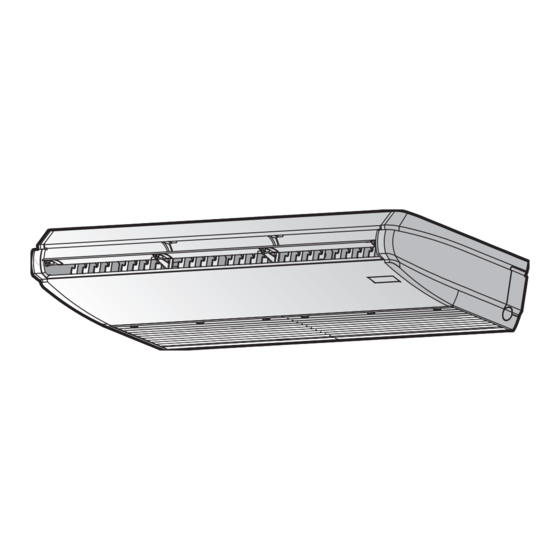
4 About the system Troubleshooting (see "8 Troubleshooting" [ 4 12]) User interface Suction air Discharge air WARNING Refrigerant piping + transmission cable Drain pipe Stop operation and shut OFF the Suction grille and air filter power if anything unusual occurs (burning smells etc.). User interface Leaving the unit running under such circumstances may cause breakage,... -
Page 9: Special Heating Operation Modes
6 Operation Up and down airflow direction setting Icon Operation mode Cooling. In this mode, cooling will be activated as INFORMATION required by the setpoint, or by Setback operation. For setting procedure of the airflow direction, see the reference guide or the manual of the used user interface. Heating. -
Page 10: To Operate The System
7 Maintenance and service To operate the system NOTICE When cleaning the heat exchanger, make sure to remove INFORMATION the electronic components above it. Water or detergent might deteriorate the insulation of electronic components For setting of the operation mode, airflow direction or other and result in burnout of these components. -
Page 11: To Clean The Suction Grille
7 Maintenance and service 1 Open the suction grille. Simultaneously slide all knobs (2 for class 32, 3 for class 63 and 100) in the direction of the arrow and carefully open the suction grille. Strap Knob 2 Remove the air filter. Push up the filter knobs at 2 places and take out the air filter. -
Page 12: Troubleshooting
Refer reference guide located https:// Stop operation and shut OFF the power if anything www.daikin.eu for more troubleshooting tips. Use the unusual occurs (burning smells etc.). search function to find your model. Leaving the unit running under such circumstances may If after checking all above items, it is impossible to fix the problem cause breakage, electrical shock or fire. -
Page 13: Mounting The Indoor Unit
12 Unit installation Front view ≥30 ≥30 (mm) (mm) Minimum and maximum distance to the floor: Top (ceiling) view ▪ Minimum: 2.5 m to avoid accidental touching. ▪ Maximum: Depends on the capacity class. See "17.1 Field setting" [ 4 20]. 4× (mm) Discharge (mm) -
Page 14: Guidelines When Installing The Drain Piping
12 Unit installation To open the indoor unit ▪ Remove the suction grille. Slide the fixing knobs to the back (2 for class 32, 3 for class 63~100), open the suction grille wide and hold the rear knob. Pull the suction grille to the front to remove it. 10 mm Hanger bracket fixing screw (M5) Hanger bracket installation bolt (M8) - Page 15 12 Unit installation ▪ Slope. Make sure the drain piping slopes down (at least 1/100) to prevent air from being trapped in the piping. Use hanging bars as shown. 1~1.5 m Hanging bar Allowed Rear left knockout part (sheet metal) Not allowed Rear left drain piping Putty or insulation (field supply)
-
Page 16: Piping Installation
13 Piping installation Drain piping connection Piping installation 13.1 Preparing refrigerant piping 13.1.1 Refrigerant piping requirements CAUTION Piping MUST be installed according to instructions given in installation" [ 4 16]. Only mechanical joints (e.g. "13 Piping braze+flare connections) that are compliant with the latest A-A' A-A' version of ISO14903 can be used. -
Page 17: Connecting The Refrigerant Piping
13 Piping installation If the temperature is higher than 30°C and the humidity is higher 1 Remove the top pipe port cover and cut out the holes for piping. than RH 80%, the thickness of the insulation materials should be at When cutting out the holes, make sure to avoid the knob part of least 20 ... -
Page 18: Electrical Installation
14 Electrical installation Components Power supply cable MUST comply with national wiring regulation. 3-core cable Wire size based on the current, but not less than 1.5 mm Transmission wiring Only use harmonised wire providing double insulation and suitable for applicable voltage Gas piping 2-core cable Liquid piping... - Page 19 14 Electrical installation 3 Install the 2 wiring fixtures with screws for wiring fixture (accessory). TO IN/D TO OUT/D 4 User interface cable: Route the cable through the large cut out hole and connect it to the terminal block (symbols P1, P2). 5 Transmission cable: Route the cable through the large cut out hole and connect it to the terminal block (make sure the symbols F1, F2 match with the symbols on the outdoor unit).
-
Page 20: Finishing The Indoor Unit Installation
NOTICE General commissioning checklist. Next commissioning instructions in this chapter, a general commissioning checklist is also available on the Daikin Configuration Business Portal (authentication required). The general commissioning checklist is complementary to 17.1 Field setting the instructions in this chapter and can be used as a... - Page 21 17 Configuration INFORMATION When the user interface thermostat Then sensor is… — ▪ The connection of optional accessories to the indoor unit might cause changes to some field settings. For Used in combination with indoor unit 10 (20) more information, see the installation manual of the thermistor optional accessory.
-
Page 22: Technical Data
▪ A subset of the latest technical data is available on the regional 0°C 12 (22) cooling 24°C/heating Daikin website (publicly accessible). 24°C ▪ The full set of latest technical data is available on the Daikin 1°C cooling 24°C/heating Business Portal (authentication required). 23°C 2°C cooling 24°C/heating... - Page 23 18 Technical data Symbol Meaning Symbol Meaning Connector (frame ground) Diode bridge, Insulated-gate bipolar transistor (IGBT) power Harness module H*P, LED*, V*L Pilot lamp, light emitting diode Wireless remote controller Light emitting diode (service Terminal monitor green) Terminal strip (block) HIGH VOLTAGE High voltage Electronic expansion valve coil...
- Page 24 3P668115-3E 2022.11 Verantwortung für Energie und Umwelt...
Need help?
Do you have a question about the FXHQ32AVEB8 and is the answer not in the manual?
Questions and answers