Table of Contents
Advertisement
Quick Links
Advertisement
Table of Contents

Subscribe to Our Youtube Channel
Related Manuals for Riello GUARD TOWER GTT 6000


Summary of Contents for Riello GUARD TOWER GTT 6000
- Page 1 GUARD TOWER GTT 6000 - 10000...
- Page 2 NTRODUCTION Congratulations on purchasing a UPS GTT Tower product and welcome to Riello UPS! To use the support service offered by Riello UPS, for USA, Canada and Mexico visit the site www.rielloupsamerica.com for other Countries www.riello-ups.com Our Company is a specialist in the design, development and manufacturing of uninterruptible power supplies (UPS).
-
Page 3: Table Of Contents
ONTENTS SAFETY AND EMC INSTRUCTIONS PRESENTATION UPS V IEWS RONT VIEW EAR VIEW ISPLAY PANEL VIEW ATTERY ABINET OPTIONAL PDU ( OPTIONAL INSTALLATION NITIAL CONTENT CHECK EMOVAL FROM THE PALLET NSTALLATION ENVIRONMENT LACEMENT ATTERY NSTALLATION ROCEDURE OWER ONNECTION NSTRUCTIONS FOR CONNECTION NTERNAL ROTECTIVE XTERNAL... - Page 4 CCESS TO THE SETTING PAGE UPS. R HERE ARE THREE PARAMETERS TO SET UP THE EFER TO FOLLOWING DIAGRAM DDITIONAL FUNCTIONS OFTWARE ONITORING AND CONTROL SOFTWARE ONFIGURATION OFTWARE OMMUNICATION PORTS RS232 CONNECTOR OMMUNICATION TROUBLESHOOTING TATUS LARM CODES TECHNICAL DATA ECHANICAL DIMENSION BATTERY CABINET...
-
Page 5: Safety And Emc Instructions
SAFETY AND EMC INSTRUCTIONS Please carefully read the following user manual and the safety instructions before installing the unit or operating the unit! IMPORTANT SAFETY INSTRUCTIONS SAVE THESE INSTRUCTIONS! 1-1. T RANSPORTATION AND TORAGE Please transport the UPS system only in the original packaging to protect against shock and impact. The UPS must be stored in a ventilated and dry location. - Page 6 1-4. C ONNECTION ARNINGS • In accordance with safety standard EN-IEC 62040-1, installation has to be provided with a back-feed Protection system, as for example a contractor, which will prevent the appearance of voltage or dangerous energy in the input mains during a mains fault. There is no standard back- feed protection inside of the UPS.
- Page 7 1-5. PERATION Do not disconnect the earth conductor cable on the UPS or the building wiring terminals since this would cancel the protective earth of the UPS system and of all connected loads. The UPS system features its own, internal current source (batteries). The UPS output may be electrically live even if the UPS system is not connected to the building wiring.
-
Page 8: Presentation
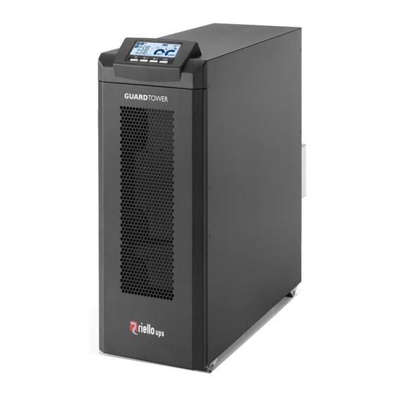
PRESENTATION GTT GUARD TOWER uses ON-LINE double conversion technology, the best solution for powering mission critical applications and electro-medical devices requiring maximum power reliability. Flexibility of installation and use (digital display, user-replaceable battery set), as well as the many communication options available, makes the GTT TOWER suitable for many different applications from IT to security. -
Page 9: Ups Views
UPS V IEWS RONT VIEW All models Display panel Removable front panel Ventilation grill... -
Page 10: Rear View
EAR VIEW Models 6 kVA Models 10 kVA Input / Output Terminal RS-232 communication port Input circuit breaker USB communication port Isolation transformer fan Emergency power off function connector (EPO Terminals cover panel (Refer to Input/Output connector) Terminal diagram for details) Share current ports External battery connector Parallel ports... -
Page 11: Display Panel View
ISPLAY PANEL VIEW “ON” button Stand-by / alarm “SEL1” button Input phase indicator “SEL2” button Measurement display area “STAND-BY” button Battery charge indicator Regular operation Configuration area Mains operation Maintenance request Battery operation Load level indicator Load powered by bypass Parallel mode indicator... -
Page 12: Battery Cabinet ( Optional )
ATTERY ABINET OPTIONAL The BATTERY CABINET, with the same dimensions and aesthetic appearance of the UPS, is an optional accessory. The BATTERY CABINET contains batteries which allow the operating time of the uninterruptible power supplies to be increased during extended blackouts. The number of batteries contained can vary according to the type of UPS for which the BATTERY CABINET is intended. -
Page 13: Pdu ( Optional )
PDU ( OPTIONAL The product is used as an external power distribution unit in conjunction with CGTT6K0GA0 / A3 or CGTT6K0GA0 / A5. C19 sockets NEMA sockets BREAKER... -
Page 14: Installation
INSTALLATION NITIAL CONTENT CHECK After opening the packaging, it is first necessary to check the contents. The UPS package must contain: User manual SNMP Card The Battery Cabinet (optional) package must contain: BATTERY CABINET Connection cable UPS - Battery Cabinet... -
Page 15: Removal From The Pallet
EMOVAL FROM THE PALLET This chapter describes the operations to remove the product from the pallet and prepare it for installation. 1. Cut the straps and open the cardboard box. 3. Remove the cardboard box by sliding it upwards and remove the side wood and PE- 2. - Page 16 6. Place the ramp in front of the pallet. Guide the product towards the front of the pallet in the direction of the ramp with caution. (*) If it will be difficult to remove the brackets, unhook the front panel pulling it from the edges; the front panel is hooked with a system of pins and springs, tools are not needed.
-
Page 17: Installation Environment
NSTALLATION ENVIRONMENT The UPS and the Battery Cabinet must be installed in ventilated, clean environments which are sheltered from bad weather. ” table. The ambient temperature and relative humidity must not exceed the maximum values shown in the "T ECHNICAL Avoid installation in locations exposed to direct sunlight or hot air. -
Page 18: Battery Installation Procedure
ATTERY NSTALLATION ROCEDURE (QUALIFIED SERVICE PERSONNEL ONLY) This UPS system does not have Hot-swappable batteries. The UPS system must be turned off to perform the Battery Installation Procedure. Remove the retaining screws for the front door (FIG. 1). Make sure the DC circuit breaker on the front panel of the UPS to the off position after removing cover. Remove the "B-L1 (6EA)"... - Page 19 5. Insert the battery according to the number (FIG. 3). 6. Install the battery cable according to the Drawing (FIG. 4).
- Page 20 7. Remove the insulating paper backing and align the edges according to the Drawing (FIG. 5). 8. Three stickers red line aligned with the edge of the insulating paper according to the Drawing (FIG. 5).
- Page 21 9. Insert the battery strip "B-L1 (6EA)" and then tighten the screws (FIG. 6). 10. Plug in the upper battery terminal and place it in the “B-L1 (6EA)” battery strip (FIG. 7). 11. Remove the "B-L2 (7EA)" screw and pull out the battery strip (FIG. 8).
- Page 22 12. Before installation, please inspect the unit. Be sure that nothing inside the package is damaged. You should have received the following items inside of package (B-L2 (7EA)). Insert the battery according to the number (FIG. 9). Install the battery cable according to the Drawing (FIG. 10). 15.
- Page 23 16. Three stickers red line aligned with the edge of the insulating paper according to the Drawing (FIG. 11). Insert the battery strip "B-L2 (7EA)" and then tighten the screws.
- Page 24 Remove the terminal fixture and plug in the left battery terminal. 19. Remove the "B-R (7EA)" screw and pull out the battery strip. 20. Before installation, please inspect the unit. Be sure that nothing inside the package is damaged. You should have received the following items inside of package (B-R (7EA)).
- Page 25 21. Insert the battery according to the number. 22. Install the battery cable according to the Drawing. Remove the insulating paper backing and align the edges according to the Drawing (FIG. 17). Three stickers red line aligned with the edge of the insulating paper according to the Drawing (FIG. 17)
- Page 26 Insert the battery strip "B-L2 (7EA)" and then tighten the screws. Plug in the right battery terminal and place the original seat terminal fixture. Install the front door and lock the set screws.
-
Page 27: Power Connection
OWER ONNECTION NSTRUCTIONS FOR CONNECTION Installation and wiring must be performed in accordance with the local electric codes/regulations by qualified service personnel. Make sure the mains wire and breakers in the building are rated appropriately for the capacity of UPS to avoid the hazards of electric shock or fire. -
Page 28: Internal Protective
Warning: ⚫ Make sure the Battery Pack DC breaker is in the OFF position before connecting the battery cable. ⚫ Pay attention to the rated battery voltage marked on the rear panel. The connection with wrong battery voltage may cause permanent damage of the UPS. Make sure the voltage of the battery pack is correct. ⚫... - Page 29 BACKFEED The UPS has internal protection against back-feed by software detection. In accordance with safety standard, installation must be provided with a Back-feed Protection system, as for example a contractor, which will prevent the appearance of voltage or dangerous energy in the input mains during a mains fault. There is no standard back-feed protection inside of the UPS.
-
Page 30: External Protective Devices
XTERNAL ROTECTIVE EVICES LINE PROTECTION: MAGNETOTHERMAL OR FUSE Within the UPS there are protection devices for output and internal faults. You must protect the input line (and the separate bypass line if present) with the appropriate protection devices. These devices must comply with the regulations of the country where the UPS is installed. -
Page 31: Connections
ONNECTIONS The first wire to be connected is the protective earth wire, which is to be inserted in the terminal marked PE. During operation the UPS must be connected to the earthing system Connect the cables to the terminals following the information provided on the label placed upon the UPS. In the images below there are some notes in relation to the installation: There are 2 sets of 120 V outputs. -
Page 32: Other Installation Modes
THER INSTALLATION MODES For more information regarding the parallel installation of the UPS, isolation transformers, accessories for maintenance Bypass and others, consult the website www.rielloupsamerica.com. ATTERY ABINET INSTALLATION ATTENTION: REFER TO THE UPS SPECIFICATION LABEL TO CONFIRM THAT THE VOLTAGE FROM THE BATTERY CABINET IS THE SAME AS THAT ALLOWED BY THE UPS. -
Page 33: Configuring The Rated Battery Capacity
ONFIGURING THE RATED BATTERY CAPACITY Before installing one or more Battery Cabinets, the UPS must be configured in order to update the rated capacity value (total Ah UPS's internal batteries + external batteries) using the dedicated configuration software. The Battery Cabinet must only be installed while the UPS is switched off and disconnected from the mains power supply. CAUTION: The connection cables cannot be extended by the user. -
Page 34: Use
WITCHING ON FOR THE FIRST TIME 1) Power on the UPS. 2) Turn on the mains input breaker and battery breaker in the back of the UPS. 3) After a few moments, the UPS will power on, the display will light up, there will be a beep and the icon will start to flash when bypass is disabled. -
Page 35: Display Panel Messages
ISPLAY PANEL MESSAGES This chapter describes, in detail, the various information that can be displayed on the LCD. STATUS MESSAGES ICON STATUS DESCRIPTION Fixed Indicates a Fault or a Lock happen Flashing The UPS is in stand-by mode Fixed Indicates regular operation when the UPS is on. Fixed The UPS is ON and operating from the mains The UPS is operating from the mains, but the output voltage is not... -
Page 36: Measurement Display Area
EASUREMENT DISPLAY AREA The front panel can be used to display important UPS operating information. When the UPS is switched-on, the display shows the main voltage value. To display a different measurement, press the “SEL1” button repeatedly until the desired measurement appears. Some measurements have more pages, press the “SEL2”... -
Page 37: Configuration Page
ONFIGURATION Access to the setting page: • To access the configuration area, hold down the “SEL1” button for at least 3 seconds, the buzzer beep once, then release the “SEL1” button, it goes to the setting page. • To change the parameters, press the “SEL1” or “SEL2” button for selecting up or down to different parameters. •... - Page 38 1. Output voltage Interface Setting Parameter 3: Output voltage You may choose the following output voltage in parameter 3: 208: Presents output voltage is 208Vac 220: Presents output voltage is 220Vac 230: Presents output voltage is 230Vac 240: Presents output voltage is 240Vac 2.
- Page 39 4. Frequency range for bypass Interface Setting Parameter 2 & 3: Setting acceptable frequency range for bypass mode. You have to set up the range by setting high and low points. When it shows “HLS” in parameter 2, please press “ON” key and it will show “HS” in parameter 2. Now, you can set up low point in parameter 3 by pressing “SEL 1”...
- Page 40 7. Frequency range for ECO mode Interface Setting Parameter 2 & 3: Setting acceptable frequency range for ECO mode. You must set up the range by setting high and low points. When it shows “HLS” in parameter 2, please press “ON” key and it will show “HS” in parameter 2. Now, you can set up low point in parameter 3 by pressing “SEL 1”...
- Page 41 12. Hot standby function enable/disable Interface Setting Parameter 2: YES.no Enable or disable Hot standby function. You may choose following two options in Parameter 2: YES: Hot standby function is enabled. It means that the current UPS is set to host of the hot standby function, and it will restart after AC recovery even without battery connected.
- Page 42 16. Output voltage adjustment Interface Setting After it shows “16” in parameter 1, please press “ON” key first. Then, you may choose Add or SUb to adjust output voltage in parameter 2 by pressing “SEL 1” or “SEL 2” key. After pressing “ON” key to confirm your selection, it will jump to parameter 3 to set up the value.
- Page 43 DDITIONAL FUNCTIONS MANUAL BYPASS Using the Manual Bypass feature, the UPS can be switched to bypass. In this condition the load is powered directly by the input mains, any disruption in the mains directly affects the load. CAUTION: BEFORE CARRYING OUT THE FOLLOWING SEQUENCE OF OPERATIONS, ENSURE THAT THE UPS’S INPUT AND OUTPUT FREQUENCY COINCIDE AND THAT THE UPS IS NOT OPERATING FROM THE BATTERY Attention: even when the UPS is switched on, the load is disconnected in the event of a mains blackout.
- Page 44 OFTWARE CAUTION: If the RS232 communication port is used, it is not possible to communicate with the USB port and vice versa. It is advisable to use a cable which is shorter than 10 ft / 3 m for communication with the UPS. To obtain additional communication ports with different functions, independent from the standard USB and RS232 ports on the UPS, various accessories are available which can be inserted into the communication card slot.
- Page 45 OMMUNICATION PORTS On the back of the UPS (see “UPS V ”), the following communication ports are present: IEWS • RS232 connector • EPO connector • USB connector • Expansion slot for additional communication cards RS232 CONNECTOR RS232 CONNECTOR PIN # SIGNAL NOTES For further information about interfacing with the UPS, refer to the...
- Page 46 TROUBLESHOOTING An irregular operation of the UPS is frequently not due to malfunctions, but to simple problems, inconveniences or distractions. Therefore, the user is advised to consult the table below providing useful information on how to solve the most common problems.
- Page 47 PROBLEM POSSIBLE CAUSE SOLUTION THE JUMPER IS MISSING THE DISPLAY SHOWS Assemble the jumper or make sure that it is inserted FROM THE R.E.P.O. THE FOLLOWING CODE: CONNECTOR OR IT IS NOT correctly. INSERTED CORRECTLY MAINTENANCE BYPASS Open the manual bypass switch (SWMB). SWITCH (SWMB) CLOSED THE DISPLAY SHOWS THE FOLLOWING CODE:...
- Page 48 PROBLEM POSSIBLE CAUSE SOLUTION Open the battery fuse holders (SWBATT) and insert the THE DISPLAY SHOWS maintenance bypass (SWMB) if present, turn the UPS off THE FOLLOWING CODE: BATTERY CHARGER FAULT completely. Turn the UPS back on and if the problem persists, contact the nearest service center Replace the fuses or close the battery fuse holder isolator BATTERY FUSES BLOWN OR...
- Page 49 TATUS LARM CODES By using a sophisticated self-diagnostic system, this UPS can check and indicate on the display panel its status and any error and/or fault occurred during operation. Whenever a problem arises, the UPS signals the event by showing the code and the corresponding alarm on the display.
- Page 50 ➢ Faults: These are more critical problems compared to the “Anomalies”, as if they persist they may bring the UPS to a halt even in a very short time. CODE DESCRIPTION Internal communication error BOOST stage anomaly Inverter stage anomaly Positive battery overvoltage Output overload Heat sink over temperature / Battery charger over temperature...
- Page 51 TECHNICAL DATA MODEL GTT 6000 GTT 10000 CAPACITY* 6000 VA / 6000 W 10000 VA / 10000 W INPUT 110 Vac(L-N) ± 3 % at 0-60% Load Low Line Loss 176 Vac(L-N) ± 3 % at 60%-100% Load Voltage Low Line Comeback Low Line Loss Voltage + 10V Range High Line Loss...
- Page 52 ECHANICAL DIMENSION BATTERY CABINET BATTERY CABINET MODEL BBX GTT xx Dimensions W x D x H [inches / mm] 9.82x24.80x30.98 / 250x630x787 Net Weight [lbs / Kg] 440.5 / 183.5...
- Page 53 Telephone +1-513-282-3777...
Need help?
Do you have a question about the GUARD TOWER GTT 6000 and is the answer not in the manual?
Questions and answers