Sign In
Upload
Download
Table of Contents
Contents
Add to my manuals
Delete from my manuals
Share
URL of this page:
HTML Link:
Bookmark this page
Add
Manual will be automatically added to "My Manuals"
Print this page
×
Bookmark added
×
Added to my manuals
Manuals
Brands
For-x Manuals
Amplifier
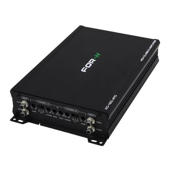
XC-160.4FD
User manual
For-x XC-160.4FD User Manual
Class d
Hide thumbs
1
2
3
4
5
6
7
8
9
10
11
12
13
14
15
page
of
15
Go
/
15
Contents
Table of Contents
Bookmarks
Table of Contents
Installation
Power Connection
Remote Control
Power Protection
Speaker Connection
Advertisement
Quick Links
Download this manual
C L A S S D A M F I
U S E R M A N U A L
XC-160.4FD
XC-250.4FD
XC-3000.1D
Table of
Contents
Previous
Page
Next
Page
1
2
3
4
5
Advertisement
Table of Contents
Need help?
Do you have a question about the XC-160.4FD and is the answer not in the manual?
Ask a question
Questions and answers
Related Manuals for For-x XC-160.4FD
Amplifier For-x XC Series Installation And Operation Manual
Competition amplifiers (12 pages)
Amplifier For-x XAQ-4.80SQ Owner's Manual
Pure rear stage power amplifie (9 pages)
Amplifier For-x XQ-48DSP User Manual
Special dsp (31 pages)
Amplifier For-x XD-180.2 User Manual
(3 pages)
Amplifier For-x XQ-500.1D Owner's Manual
(10 pages)
Amplifier For-x XQ-80.4D Owner's Manual
(10 pages)
Amplifier For-x XQ-125.4D Owner's Manual
(10 pages)
Amplifier For-x XQ-225.4D Owner's Manual
(10 pages)
Amplifier For-x XC-250.4FD User Manual
Class d (15 pages)
Amplifier For-x XAP-7000.1D Owner's Manual
High performance amplifier (25 pages)
Amplifier For-x X-9102A User Manual
(15 pages)
Amplifier For-x XAQ-1216DSD Owner's Manuel
Digital signal processor amplifier (30 pages)
Amplifier For-x XAP-200.4D Owner's Manual
High performance amplifier (25 pages)
Amplifier For-x XAD-2100.1D Owner's Manual
High performance amplifier (29 pages)
Amplifier For-x XM-300.4D Owner's Manual
Marine digital amplifier (25 pages)
Amplifier For-x XQ-4860DSP Owner's Manual
Digital signal processor amplifier (29 pages)
This manual is also suitable for:
Xc-250.4fd
Xc-3000.1d
Table of Contents
Print
Rename the bookmark
Delete bookmark?
Delete from my manuals?
Login
Sign In
OR
Sign in with Facebook
Sign in with Google
Upload manual
Upload from disk
Upload from URL


Need help?
Do you have a question about the XC-160.4FD and is the answer not in the manual?
Questions and answers