Sign In
Upload
Manuals
Brands
AND Manuals
Accessories
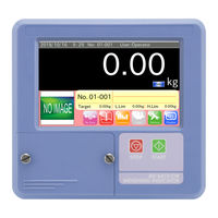
AD-4413-CW
AND AD-4413-CW Manuals
Manuals and User Guides for AND AD-4413-CW. We have
1
AND AD-4413-CW manual available for free PDF download: Instruction Manual
AND AD-4413-CW Instruction Manual (164 pages)
Weighing Indicator
Brand:
AND
| Category:
Accessories
| Size: 7 MB
Table of Contents
Table of Contents
3
Introduction
9
Features
9
Safety Precautions
10
Compliance
11
Parts Names
12
Front Panel
12
Rear Panel
13
Installing the Weighing Indicator
14
USB Flash Drive
14
Connecting USB Flash Drive
14
Removing USB Flash Drive
14
Installing Option Board
15
Mounting the Weighing Indicator on Panel
15
Panel Mount Kit ( AD-4412-10 )
16
Attachment Kit ( AD-4412-11 ) for Indicator Stand ( AD-4402-25 )
17
Connecting Load Cell Cables
18
Connecting Power Lines
19
Operation Window
20
Icon
20
Numerical Input
20
Pull down Menu
21
IP Address
21
Alphanumeric Input
22
Password Input
22
Basic Operations
23
Operation Outline
23
Turning on the Power
24
Turning off the Power
24
Weighing Operations
25
Changing the Indication of Weighing Value
25
Adjusting Zero Point (to Display Zero)
26
Starting and Stopping the Weighing Operation
26
Managing User Level for Logging in
27
Management Level of User
27
Changing User
28
Registering User
29
Changing User Information
30
Deleting User
31
Selection of Products and Detection Function
33
Registering Products
33
Settings of Threshold Values ( Target, Hihi Limit, Hi Limit, lo Limit, Lolo Limit )
35
Setting Product Length and Velocity
36
Setting the Digital Output (DO)
37
Setting the Delay Time and Holding Time
38
DO Test Function
39
Setting a Tare Value
39
The Selection of Weighing Product
40
The Registration of Product Image
40
Creating a Copy of Product Settings
41
Deleting Product Settings
42
Summary of Weighing Result
43
Weighing History
43
All Summary
44
OK Summary
44
Number of Samples Summary
45
Number of OK Samples Summary
46
Histogram
47
Control Chart
48
Control Chart
49
Adjustment Operations for the Indicator
50
Calibrating the Indicator Using a Weight
50
Settings for Date and Time
52
Setting up LAN Interface
53
Output of Weighing Results and Summary
54
Output to USB Flash Drive
54
Output of Weighing History
54
Example: Output File of Weighing History
55
PDF Output of Histogram, Control Chart and Summary
56
Output to the Postscript Printer
57
Output to Postscript Printer
57
Printing Sample of Histogram
58
Print Sample of Control Chart
59
Print Sample of Summary
60
Output to the Dump Printer
61
Print Samples
62
Peripherals
66
Format of USB Flash Drive
66
Connecting the LAN Interface
67
How to Connect to Network Using Wired LAN
67
How to Connect to Network Using Wireless LAN
67
Connecting the Postscript Printer
68
Remote Monitor
68
Replacing Product Using Serial Communication
69
The Details of Settings
70
Product Name and Product Code
74
Product Name
74
Product Code
74
Detect Basis
74
Reject Stage ( Count of Separation )
74
Target
74
Hihi Limit
74
Hi Limit
74
Lo Limit
75
Lolo Limit
75
Over Weight Exception
75
Consecutive Fail Stop
75
Consecutive Fail Num
75
Detect Parameter
76
Product Length
76
Speed
76
Weighing Mode
76
Conveyor Stop Timer
76
Product Detection
77
Near Zero Range
77
Auto Mode ( to Set Parameters)
77
DO Map (Digital Output Map)
78
DO Map Reference
78
Output Definition of DO Map
78
Control I/O (Part of Digital Output)
81
DO Behavior
81
Delay Time
81
Hold Time
81
Polarity
81
Statistics
82
Num of Samples
82
Sub Samples
82
Width of Section
82
Tare
83
Auto Zero
83
Auto Zero Range
83
Dead Zone Timer
83
Observation Timer
84
Averaging Time
84
Auto Zero Sample
84
Coe (Coefficient)
84
Comp. Value
84
Feedback Control (FC)
85
Feedback Control Target
86
Feedback Control Range
86
Feedback Control Step : [G/Sec.] or [Sec./G]
86
Feedback Control Sample
86
Feedback Control Waiting Time
86
Step Control
87
Control Target
87
Zone 1 to 4 of 10 Stage Control
88
Sample
88
Wait Time
88
Weighing
89
Unit
89
Decimal Point
89
Division
89
Capacity
89
Digital Filter
89
Zero Point Range
89
Power on Auto Zero Range
89
Zero Tracking Time
90
Zero Tracking Weight
90
Stability Time
90
Stability Weight
90
Cal (Calibration)
91
Weight
91
Zero Point
91
Span
91
Main Unit
92
Identification Name
92
Start up User Level
92
Conveyor Length
92
Unsplit Range
92
Conveyor Mode
92
Connect Device Priority
92
Curb Chattering
93
Photo Eye Sensor Polarity
93
Photo Eye Sensor Timeout
93
Random Check (to Input Data Previously)
93
Display
94
Language
94
Display Mode
94
Negative Weight
94
Display Data
94
Standby Mode
94
Brightness
94
Connection
94
Printer IP Address
94
DI Map (Digital Input Map)
95
Control I/O (Part of Digital Input)
95
Input Trigger
96
Configuration
98
Delay Time
101
Chattering
101
DI Indicator
102
Analog out
103
Data Types
103
Output Format
103
Low Voltage Standard
103
High Voltage Standard
103
Low Voltage Output
103
High Voltage Output
103
Low Current Standard
103
High Current Standard
103
Low Current Output
103
Device
104
Model Name
104
Serial Number
104
GUI Software Version
104
Weighing Software Version
104
Option Port 1 and 2
104
Date / Time
104
Date Set
104
Time Set
104
USB Flash Drive
104
Modbus
105
Slave Address
105
Output Format
106
Rs-232C
108
RS-232C Port
108
Output Mode
108
Baud Rate
108
Parity
108
Stop Bit
108
Data Bit
109
107
109
Port
109
Output Mode
109
Baud Rate
109
Parity
109
Stop Bit
109
Lan
110
CL IP Address
110
CL Subnet Mask
110
CL Default Gateway
110
WL Port
110
WL IP Address
110
WL Password
110
Monitor
111
Rs-232C
111
110
112
Control I/O
112
Relay Output
113
Parallel I/O
113
Analog Output
114
Modbus Communication
115
Using Modbus RTU
116
Using Modbus TCP
116
Communication Command of Modbus
117
Example of Reading Input Register
117
Example of Writing Holding Register
118
Example of Exception Response
119
Reference Number
120
Address
120
Communication Command of Modbus TCP
144
Protocol Layout
144
Example of Reading Input Register
144
Interface
145
Control I/O
145
Connection of Control I/O
145
Rs-232C
146
Connection of RS-232C
146
145
147
Connection of RS-485
147
Photo Eye Sensor
148
Connection of Photo Eye Sensor
148
Relay Output
148
Parallel Input / Output
150
Analog Output
152
The Way to Set Output Current
153
Additional Analog Output Module
153
Maintenance
154
Error Messages of Indicator
154
Error Message Table
154
Backup of System Data
155
Restoring System Data
156
Initialization to Factory Settings
158
Specifications
159
Dimensions
160
Ad-4412-Cw
160
Ad-4413-Cw
161
Advertisement
Advertisement
Related Products
AND AD-4412-CW
AND Multi Function Weighing Indicator AD-4402
AND Weighing Indicator AD-4401
AND Weighing Indicator AD-4407
AND AD-4430B
AND AD-4401A
AND AD-4406 OP-04
AND AD-4406 OP-07
AND AD-4406 OP-08
AND AD-4406 OP-11
AND Categories
Scales
Blood Pressure Monitor
Accessories
Measuring Instruments
Recording Equipment
More AND Manuals
Login
Sign In
OR
Sign in with Facebook
Sign in with Google
Upload manual
Upload from disk
Upload from URL