
Subscribe to Our Youtube Channel
Related Manuals for SKF FB


Summary of Contents for SKF FB
- Page 1 FB/FB-ATEX Assembly instructions acc. to EC Dir. 2006/42/EC for partly completed machinery with associated operating instructions Multiline pump units Operating instructions acc. to Dir. 2014/34/EC, Annex X Version 04...
- Page 2 Page 2 Notes Multiline pump units FB; FB ATEX Service Masthead © SKF Lubrication Systems Germany GmbH If you have technical questions, please contact These assembly instructions with associated This documentation is protected by copyright. the following addresses: operating instructions according to EC...
-
Page 3: Table Of Contents
11. Accessories Electronic and electrical devices 3. Overview 12. Spare parts General notes 4. Assembly 12.1 Spare parts list for FB multline Lifters Setup and attachment pump unit 4. Assembly 4.1.1 Assembly of the pumps FB 12.2 Spare parts list for FB-ATEX... - Page 4 EC Declaration of Incorporation EC Declaration of Incorporation according to Machinery Directive 2006/42/EC, Annex II Part 1 B The manufacturer SKF Lubrication Systems Germany GmbH Hockenheim Plant, 2. Industriestr. 4, DE - 68766 Hockenheim hereby declares that the partly completed machinery:...
- Page 5 EU Declaration of conformity EU Declaration of conformity following ATEX directive 2014/34/EU, annex X The manufacturer SKF Lubrication Systems Germany GmbH Hockenheim Plant, 2. Industriestr. 4, DE - 68766 Hockenheim hereby declares that the apparatus Designation: FB/FB-ATEX Multiline pump units Type: FB*D4128*;...
-
Page 6: Explanation Of Safety And Informational Symbols And Safety Signal Words
Page 6 Explanation of symbols Explanation of safety and informational symbols and safety signal words You will ind these symbols, which warn of Instructions placed directly on the machines/ speciic dangers to persons, material assets, or grease lubrication pump unit, such as: the environment, next to all safety instructions Arrow indicators in these operating instructions. -
Page 7: Safety Instructions
Note that the assembly instructions Pump units of SKF's FB series are used to supply described product is incorporated. Such per- form part of the product and must... -
Page 8: Electric Shock Hazard
Page 8 Assembly instructions Electric shock hazard Hydraulic pressure hazard Electrical connections for the described prod- Danger! The described product is pressurized during operation. The product must uct may only be established by qualified and The protective earth connector must therefore be depressurized before trained personnel authorized to do so by the always be connected. -
Page 9: Explosion Protection Information
Danger! The unit must be grounded via a ground connection. The customer must install expected. Only the FB pump models tested and adequate overload protection for the approved by SKF Lubrication Systems The lubricant’s ignition temperature has power consumption of the motor. -
Page 10: Lubricants
Regulation EC 1272/2008 may only be used manufacturer and/or the operator of the ma- chine/system in cooperation with the lubricant to fill SKF centralized lubrication systems and components and deliv-ered and/or distributed supplier. with the same after consulting with and re- When selecting a lubricant, the type of bear- ceiving written approval from SKF. -
Page 11: Approved Lubricants
The described product can be operated using You can request an overview of the lubricant lubricants that meet the specifications in the tests offered by SKF Lubrication Systems technical data. Depending on the product de- It is important to note that lubricants are envi-... -
Page 12: Lubricant Hazards
Page 12 Assembly instructions Lubricant hazards for information regarding transport, storage, Centralized lubrication systems must Lubricants are hazardous substances. The always be free of leaks. Leaking processing, and environmental hazards of the safety instructions on the lubricant's safety lubricant is hazardous due to the risk lubricant that will be used. -
Page 13: Overview
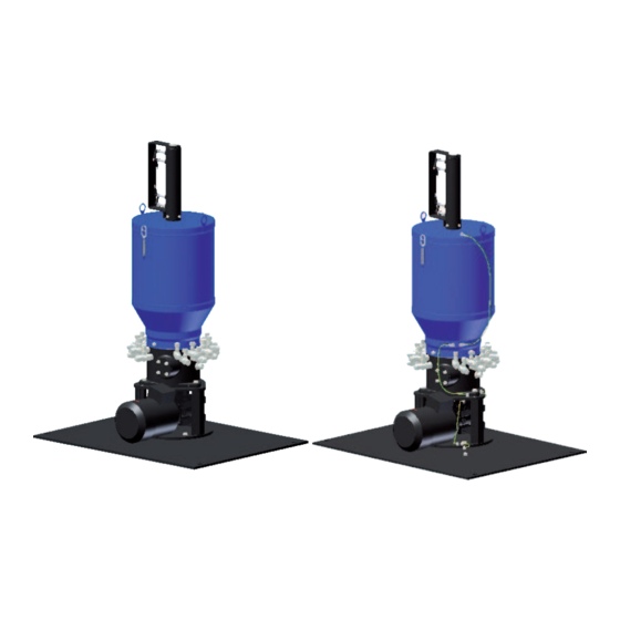
Page 13 Assembly instructions 3. Overview Components of the FB, FB-ATEX unit, Fig. 1 Components of the unit Item Description 1 Fill level switch, 4 switching points 2 Reservoir cover (with fill level control) 3 Lubricant reservoir 4 Grease follower plate... -
Page 14: Assembly
Pressure gauges, oil level glasses, temperature The number of pump elements can also be gauges and other visual monitoring equipment FB and FB-ATEX multiline pump units are al- changed later. The pump has to be shut done must be clearly visible. - Page 15 Gently tighten hexagon head screws (4x). Warning! Do not tilt or drop the FB multiline Align the mounting plate and tighten the pump unit! hexagon head screws with the following tightening torque:...
-
Page 16: Port Dimensions
Page 16 Assembly instructions Port dimensions 4.2.1 Assembly drawing for FB and FB-ATEX Assembly drawing for FB and FB-ATEX multiline pump unit, Fig. 2 Minimum mounting dimensions Dim. Min. install dimension [mm] 1400 FB ATEX Multiline pump unit Multiline pump unit... - Page 17 Page 17 Assembly instructions FB and FB-ATEX multiline pump unit, Fig. 3 second row t=10 rst row Ø 20 Baseplate 10 9 Maximum dimensions rst row second row...
-
Page 18: Electrical Motor Connection
Page 18 Assembly instructions Electrical motor connection +3/-5% frequency deviation). This applies es- Details regarding electrical connection of the Electric shock hazard pecially with regard to heating and deviations motor to the power supply, especially terminal Electrical connections for the product in operating parameters from the ratings on and connector pin assignment, can be taken may only be established by qualiied... -
Page 19: Fb Motor Ratings
Page 19 Assembly instructions 4.3.1 FB motor ratings Danger! FB motor ratings The protective earth connector must Synchron. Frequen- Rated power Rated voltage Rated current Order code always be connected. Ensure that the speed [kW] contact is secure and that the connec-... -
Page 20: Assembly Of The Electric Ill Level Switches
4.3.3 FB- Assembly of the electric ill level switches Fill level switch J Dimensions for fill level switch on FB multline pump unit, Fig. 4 Proximity switch (4x) Design ....PNP, XOR, short-circuit-proof, 1. -
Page 21: Fb-Atex Assembly Of The Electric Ill Level Switches
Page 21 Assembly instructions 4.3.4 FB-ATEX Assembly of the electric ill level switches Inductive proximity switch per Namur ATEX proximity switch Dimensions fill level switch on FB-ATEX, Fig. 5 DIN EN50227 Proximity switch (4x) Design ... . . inductive, per Namur . -
Page 22: Attaching Ground Connection To Fb-Atex
Page 22 Assembly instructions 4.3.5 Attaching ground connection to FB-ATEX Grounding the FB-ATEX multiline pump unit, Fig. 6 Warning! Step 1 The standard grounding cable pro- vided by the customer must have a minimum cross-section of 6 mm On the grounding bolt (1), loosen the mounting nut (2) (WAF 13). -
Page 23: Lubrication Line Connection
Tighten the union nut (2) with an open-end Legend to Figure 7 wrench. ized lubrication systems, SKF cutting-sleeve Item Description screw unions conforming to DIN 2353 can be Lubrication line, varying acc. to used. -
Page 24: Lubrication Line Arrangement
Page 24 Assembly instructions Lubrication line arrangement When arranging the main and secondary lu- In addition, the lubrication line system needs to The flow of lubricant in the lubrication lines bricant lines, observe the following instruc- be protected from excessive pressure by means should not be hindered by the installation of tions in order to ensure that the entire lubri- of a pressure-limiting valve. -
Page 25: Note On The Rating Plate
Page 25 Assembly instructions Note on the rating plate Warning! The rating plates on the multiline pump units Enter key data from rating plate in the Follow the safety instructions on the following table. provide important data such as the type des- lubricant's safety data sheet. - Page 27 FB/FB-ATEX Operating instructions associated Multiline pump units with assembly instructions according to EC Dir. 2006/42/EC for partly completed machinery...
-
Page 28: Operating Instructions
The safety instructions listed in Chapter 1, Caused by the installation of non-original SKF components or SKF spare parts "Safety instructions," of the assembly instruc- tions also apply without restrictions to these Caused by inappropriate usage operating instructions. -
Page 29: Transport, Delivery, And Storage
3. Transport, delivery, and storage Page 29 3. Transport, delivery, and storage Lubrication units Notes SKF Lubrication Systems Germany GmbH products are packaged in accordance with Ambient conditions: dry and dust-free The component(s) can be enveloped in surroundings, storage in well ventilated dry... -
Page 30: Lifters
Lifters Transport device, Fig. 1 Four lifting lugs are attached to the baseplate of FB and FB-ATEX multiline pumps for trans- port purposes. These are color coded. FB and FB-ATEX multiline pump units with baseplate may only be lifted and transported using these lifting lugs. -
Page 31: Assembly
Information on assembly 4.2 4.2 Assembly of FB multiline pump Dismantling and disposal units The assembly procedure for the FB and FB- Warning! ATEX multiline pump units is described in de- Assembly must be performed in accordance The applicable national environmen-... -
Page 32: Design And Function
The customer evaluates the signals. The eccentric movement of the cam discs (4) FB multiline pump units are filled exclusively (5) forcibly moves the attached delivery pis- through the filler socket attached to the pump tons of the pump elements, which ensures a housing (16). -
Page 33: Pump Element Operation
5. Design and function Page 33 Pump element operation The delivery piston is forcibly actuated as de- The pump element is now prepared for the With the ATEX design, the screw plug is replaced by a pressure regulating valve. scribed in "Pump operation." In the suction next lubrication cycle. -
Page 34: Commissioning
Page 34 6. Commissioning 6. Commissioning Commissioning / recommissioning Observe the instructions from the ma- chine manufacturer regarding the See Figure 4. Filling with oil as described be- Switch on the grease lubrication pump lubricants that are to be used. low is only intended for the pump unit's briefly (for about 1 second) and check the venting procedure. -
Page 35: Varying Pump Displacement
6. Commissioning Page 35 Varying pump displacement Pump design, Fig. 4 Start (switch on) the grease lubrication The pump elements are factory-set to maxi- pump mum pump output. After commissioning, the output can be adjusted to meet output re- Allow pump to run until bubble-free quirements, as described in the following. - Page 36 Page 36 6. Commissioning Adjust the displacement Displacement chart, Fig. 5 Using the hexagon socket screw key, ad- See Figure 5 just the setting sleeve (2) for the required displacement (notches 1 to 8 - see dis- Place a hexagon socket screw key (WAF 6) placement chart).
-
Page 37: Shutdown And Disposal
Observe the local regula- tions and laws regarding the disposal of Notes Assembly instructions. lubricants. The product can also be returned to SKF Lubrication Systems Germany GmbH for dis- posal, in which case the customer is respon- sible for reimbursing the costs incurred. -
Page 38: Maintenance
If this occurs, before opening any of the product's please contact the Service department of SKF SKF Lubrication Systems Germany GmbH components. Lubrication Systems Germany GmbH for shall not be held liable for damages resulting assistance. -
Page 39: General Information
8. Maintenance Page 39 General information Visual inspection FB multiline pump units function without Visual inspection every 100 operating hours maintenance in principle. However, make sure that the grease level does not fall below the Item Component Check strainer, in order to prevent air being drawn into the pump elements. -
Page 40: Removing A Pump Element
Page 40 8. Maintenance Removing a pump element Sectional view of pump element, Fig. 7 See Figure 7 Release the union nut (1) on the ring piece (2) grease, remove it from the pump housing with tweezers or a magnet. Remove the lubrication line from the ring piece (2) Loosen the cap nut (5) and pull off the ring... -
Page 41: Installing A Pump Element
8. Maintenance Page 41 8.4 Installing a pump element Pump element disassembly, Fig. 8 See Figure 8 Fill the cylinder chamber of the screw-in cylinder (2) with (clean) grease. Warning! Pump elements must not be connected Carefully guide the delivery piston (1) into to the connection for the lubrication the cylinder chamber of the screw-in cylin- line. - Page 42 Page 42 8. Maintenance Screw-in cylinder installation, Fig. 9 Torques in Nm See Figure 9 Pump element with piston diameter of: Screw the screw-in cylinder (2) ) into the 6 mm pump housing and tighten. Screw-in cylinder (2) 80 Nm Screw socket 70 Nm See the "Torques"...
- Page 43 8. Maintenance Page 43 Installation of ring piece and cap nut, Fig. 10 See Figure 10 Put the screw plug (8) in position and tighten it using a hexagon socket screw key (WAF 8). Fit the ring piece (4) and cap nut (5 ) on the screw socket (3) and tighten by hand.
-
Page 44: Malfunctions
9. Malfunction The following tables provide an overview of Warning! possible malfunctions and their causes. Only original spare parts from SKF The hot surface of a motor may cause burns. Motor surfaces may only be Contact the Service department of SKF... -
Page 45: Commissioning Malfunctions
9. Malfunction Page 45 Commissioning malfunctions Commissioning malfunctions Malfunction Cause Remedy Displacement volume Air in the pump element Vent and fill as instructed in Chapter 6.1, "Commissioning" and/or delivery pressure too low without supply Driveshaft rotating in wrong direction Check electrical connections and voltage lines connected Driveshaft speed is too low Remove foreign substances if agitator or pump element is... -
Page 46: Operational Malfunctions
Page 46 9. Malfunction Operational malfunctions Operational malfunctions, Table 1 of 2 Malfunction Cause Remedy Displacement Air in the pump element Vent and fill as instructed in Chapter 6.1. volume or deliv- ery pressure too Pump element is clogged Malfunction „No delivery“ low without lines connected Driveshaft speed is too low... - Page 47 9. Malfunction Page 47 Operational malfunctions, Table 2 of 2 Malfunction Cause Remedy No delivery Pump element is defective Replacing the pump element Vent and fill as instructed in Chapter 6.1. Spring pressure, delivery piston breaking loose Install the pump element as instructed in Chapter 8.4 Guide ring for the pump element piston heads is Replace the guide ring, and vent the pump as instruc- ted in Chapter 6.1 - Commissioning...
-
Page 48: Malfunctions On Ill Level Control
Page 48 9. Malfunction 9.3 Malfunctions on ill level control Fill level control malfunctions Malfunction Cause Remedy Lubricant over grease fol- Seal on the grease follower plate is leaking Replace the seal lower plate Lubricant comes out of the No signal Check the cable connection;... -
Page 49: Technical Data
Weight... . . Approx. 51 kg Operating pressure for pump elements (FB multiline pump unit with foot guard, with 2) Other specifications available on request. piston Ø 6 . . . max. 350 bar monitoring, without pump elements) piston Ø... -
Page 50: Accessories
Page 50 11.Accessories 11. Accessories Pressure regulating valves for grease (for insertion into pump elements) Pressure regulating valve Set pressure Weight Order No. [bar] [kg/each] 0.13 24-2103-2273 0.13 24-2103-2344 0.13 24-2103-2345 0.13 24-2103-2342 0.13 24-2103-2272 0.13 24-2103-2346 SW24 0.13 24-2103-2271 Pump element with ring piece (for installing a pump element) Pump element Description... - Page 51 11.Accessories Page 51 Screw plug Screw plug (for closing unused pump outlets) Design Weight kg/each Order No. M20x1.5 0.037 95-1520-0908 Threaded socket for grease recirculation Threaded socket (in place of a pump element to recirculate grease into pump housing) Design Order No.
-
Page 52: Spare Parts
Page 52 12. Spare parts 12. Spare parts 12.1 Spare parts list for FB multline pump unit Spare parts for FB multiline pump unit 0019 0005 0006 43, 44 13...16... - Page 53 12. Spare parts Page 53 Spare parts for FB multiline pump unit Item Quantity Description Order number Pump element, piston Ø 6 mm 24-1557-3680 Pump element, piston Ø 8 mm 24-1557-3681 Pump element, piston Ø 10 mm 24-1557-3683 Ring piece for pipe connection Ø 8 mm...
-
Page 54: Spare Parts List For Fb-Atex Multiline Pump Unit
Page 54 12. Spare parts 12.2 Spare parts list for FB-ATEX multiline pump unit Spare parts for FB-ATEX multiline pump unit 0019 0005 0006 43, 44 13...16... - Page 55 12. Spare parts Page 55 Spare parts for FB multiline pump unit Item Quantity Description Order number Pump element, piston Ø 6 mm 24-1557-3680 Pump element, piston Ø 8 mm 24-1557-3681 Pump element, piston Ø 10 mm 24-1557-3683 Ring piece for pipe connection Ø 8 mm...
- Page 56 All SKF products may be used only for their intended purpose as described in these assembly instructions with associated operating instructions. If assembly/operating in- structions are supplied together with the products, they must be read and followed.
Need help?
Do you have a question about the FB and is the answer not in the manual?
Questions and answers