SKF FlowMaster II User And Maintenance Instructions
B cat branded rotary driven hydraulic pump
Hide thumbs
Also See for FlowMaster II:
- User and maintenance instructions (24 pages) ,
- Manual (88 pages) ,
- User and maintenance instructions (24 pages)

Subscribe to Our Youtube Channel
Related Manuals for SKF FlowMaster II


Summary of Contents for SKF FlowMaster II
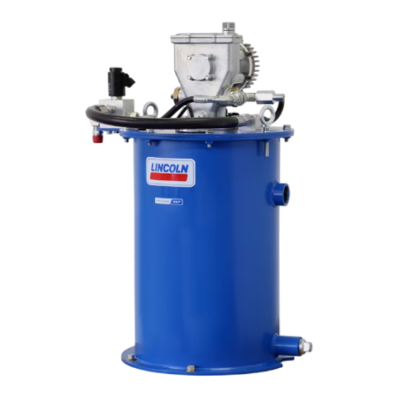
- Page 1 User and maintenance instructions FlowMaster II rotary driven hydraulic pump Models 85705 and 85705MSO, series “B” CAT branded Date of issue January 2021 Form number 404581 Version...
-
Page 2: Table Of Contents
Contents Explanation of Safety safety signals Read and carefully observe these installation instructions before installing, Explanation of safety signals ..operating or troubleshooting assembly. NOTE Safety ......Assembly must be installed, maintained and Emphasizes useful hints and Description. -
Page 3: Description
(24 V ) “on” and “off” valve. When lubrication cycle has completed, FlowMaster II pump is fully automatic pressure rises in system to actuate pressure when used with a controller and pressure switch. When pressure switch actuates, switch. -
Page 4: Pump Assembly
Pump assembly Maintenance Outlet check and repair inspection and Refer to manual 404582 for repair bare pump assembly (35) General maintenance (Fig. 2, page 7). • Keep area around pump clean. Clean off Before starting this procedure, refer to filling port area prior to filling reservoir. Troubleshooting, page 11, to determine if Clean area around filler after filling as outlet check valve is cause of failure. -
Page 5: Vent Valve Service
Vent valve service ○ Is sensor body (38) securely NOTE fastened to drum cover (32) Install elbow (24) facing down and rotate approximately 30° toward vent hose to (Fig. IPB 1, page 7). prevent excessive rubbing of hydraulic hose Before starting this procedure, refer to ○... -
Page 6: Mechanical Shut-Off Valve
Fig. 1 85705MSO only All ports are in NPTF. Apply two drops of 242 Loctite, 180° apart. Torque from 30 to 35 ft-lbf (41 to 47 Nm). Mechanical shut-off valve Mechanical shut-off valve automatically shuts off filling of reservoir without power applied to system. - Page 7 Fig. 2 18.9 in (479 mm) 22.5° 15 / in (384 mm) 13 / in (352 mm) / in (13 mm) 29.2 in (741 mm)
-
Page 8: Illustrated Parts Breakdown
Fig. IPB 1 Fig. IPB 2 Outlet check assembly (3) Vent valve (23) / NPTF Fig. IPB 3 Fig. IPB 4 Float switch (38) Cover plug... - Page 9 Fig. IPB 5 Follower assembly (39)
-
Page 10: Service Parts
Service parts Item Description Quantity Part no. Item Description Quantity Part no. Elbow, NPTF 277439 Steel ball, 66001 Adapter 12213 Outlet connector 90860 Outlet check assembly 81938 Cylinder 241807 Vent hose 270726 Piston and u-cup assembly 244673 1) 2) Elbow connector, #4 ORB x #6 ORFS 273100 Needle 14722... -
Page 11: Troubleshooting
Troubleshooting Condition Possible cause Corrective action Pump does not operate. No hydraulic power to pump. Turn on or connect hydraulic supply to pump. No pressure on gauge: • Closed supply line shut off valve. Open shut-off valve. • No power to solenoid valve. Correct electrical fault. -
Page 12: Warranty
® SKF and Lincoln are registered trademarks of the SKF Group. © SKF Group 2021 The contents of this publication are the copyright of the publisher and may not be reproduced (even extracts) unless prior written permission is granted. Every care has been taken to ensure the accuracy of the information contained in this publication but no liability can be accepted for any loss or damage whether direct, indirect or consequential arising out of the use of the information contained herein.
Need help?
Do you have a question about the FlowMaster II and is the answer not in the manual?
Questions and answers