Table of Contents
Advertisement
Quick Links
Advertisement
Table of Contents

Related Manuals for Wohler M 603


Summary of Contents for Wohler M 603
- Page 1 Operating Manual Pressure Meter Part 1 Wöhler M 603 The Measure of Technology...
-
Page 2: Table Of Contents
Charging the battery ........19 Leak tightness test ........20 Starting the unit ........20 Connecting the Wöhler M 603 to one or more Wöhler SC 660 units ....21 Connection via the settings menu ....22 Connection during live measurement ..23 Connection prior to pressure testing with water .............. - Page 3 General information Leak tightness test on gas pipes ....30 Usability measurement on gas pipes ... 34 8.3.1 Usability testing, volume flow measurement 35 8.3.2 Usability testing, pressure drop method ..44 Pipe volume measurement ......51 8.4.1 Pipe volume measurement, automatic ..51 8.4.2 Pipe volume measurement, manual ....
-
Page 4: General Information
Information about this This operating manual enables you to work safely with the Wöhler M 603. Keep this manual in a safe operating manual place so you can refer to it when needed. The Wöhler M 603 Pressure Meter is intended to be used solely by trained professionals and must only be used for its intended purpose. -
Page 5: Components
2018 - G 600) Measurement of flow pressure, installation pres- sure, standing pressure, jet pressure Components Product Items supplied Wöhler M 603 Pressure meter Control report Measuring hose (1.7 m) with quick-release connector USB A / USB C cable USB power supply unit... -
Page 6: Manufacturer
Important information Manufacturer Wöhler Technik GmbH Wöhler-Platz 1 D-33181 Bad Wünnenberg Tel.: +49 2953 73-100 Fax: +49 2953 73-250 E-mail: info@woehler-international.com Important information WARNING! Due to the compressibility of gases, for technical safety reasons the relevant accident prevention regulations (Germany: “Arbeiten an Gasanlagen” / Work on Gas Systems and Equipment) and the set of rules “Technische Regeln für Gasinstallationen DVGW- TRGI”... -
Page 7: Specification
Specification Specification Measured values Differential pressure measurement Description Reading (temperature-compensated piezo bridge) Measuring range ± 3,000 hPa Permissible overload ± 3,200 hPa Accuracy < 3% of the measured value; in the range < ± 2 hPa better than ± 0.06 hPa Resolution 0.01 Pa in the range from... - Page 8 Specification External temperature measure- Description Reading ment Measuring range 2 channels, -20.0°C to (optional, e.g. with a temperature +800.0°C clamp probe or surface tempera- ture sensor) Accuracy < ± 1°C in the range from -20°C to 67°C, otherwise 1.5% of the measured value, in acc.
-
Page 9: Calculated Values
Specification Calculated values Calculated Calculation parameter Pressure units Conversion to hPa, Pa, O, PSI, in , bar, mbar in accordance with the gen- erally accepted conversion guidelines. Temperature Conversion from °C to °F in units accordance with the general- ly accepted conversion guidelines. -
Page 10: Logger Function
Specification Logger function Description Reading Scope 9999 measurements, each with measured values for pressure and humidity, as well as three measured val- ues for temperature (with external sensors connected) with freely selectable scanning intervals ranging from 1 second to 24 h can be saved in the inter- nal memory. -
Page 11: Technical Data
Specification Technical data Description Reading Display 5” Power supply Lithium-ion rechargeable battery 3.7 V, 6700 mAh, charged via USB Battery life: approx. 17 h (depending on the operating sta- tus and brightness of the display) Charging time: approx. 7 h Battery charging cy- After 500 charging cycles at least 70% of the battery's ca- cles... -
Page 12: Layout And Functions
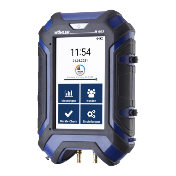
Layout and functions Layout and functions Basic device Fig. 2: Wöhler M 603 Pressure Meter Connector panel Fig. 3: Wöhler M 603 Pressure Meter: connector panel... - Page 13 Layout and functions Number Function ON/OFF button USB C port / charging connection Color display Fastening lugs for carrying strap Connector panel Gas bellows connection (for usability testing with gas) 7 Pressure connection Main connection for measurement of gas leakage amount 8 Pressure connection (-- Reference connection for differential pressure meas-...
-
Page 14: Protective Covers
NOTE! Refer to and comply with accident prevention regu- lation BGR 500, section 2.31 “Work on gas pipes.” Fig. 5: Connection of the Wöhler M 603 for automatic usability measurement with filled gas bellows Connect the gas bellows at the opening be- •... - Page 15 Layout and functions Connection fittings for performance of a stress test (manually) Fig. 7: Connection fittings for manual inflation Connections of the Wöhler leak tightness testing set for gas pipes: 1 Valve block 2 Connecting hose to the pressure meter 3 Connecting hose to the air pump 4 Connecting hose to the gas pipe Connections for differential pressure measurement...
- Page 16 Then connect the 10 cm hose sections to the • burner connection. Now switch on the Wöhler M 603 and read off • the differential pressure in the live measure- ment (see part 2 of the operating manual).
-
Page 17: Touch Display
Layout and functions Touch display Active buttons have a blue or white background. Inactive buttons have a gray background. If a bar can be seen on the right-hand edge of the display, this means that you can also scroll the dis- play by dragging it up or down with your finger. - Page 18 Layout and functions Bluetooth symbols in the header NOTE! The Bluetooth function can be enabled and disa- bled in the settings menu – refer to part 2 of the operating manual. Bluetooth disabled Searching for Smart Connect sensor Bluetooth connection established Battery charge indicator in the header Battery is fully charged Battery is completely empty...
-
Page 19: Prior To Use
Prior to use Prior to use Charging the battery NOTE! The battery is permanently installed in the device and cannot be removed by the operator. When the unit is switched on, the battery charge status is indicated at the top right of the display. When the battery is fully charged, the battery icon is completely filled. -
Page 20: Leak Tightness Test
Starting the unit the unit via the USB C charging port (see Fig. 1) and then connect the power supply to the mains. Leak tightness test • Perform a leak tightness test in accordance with part 2 of the operating manual, section 4.2. -
Page 21: Connecting The Wöhler M 603 To One Or More Wöhler Sc 660 Units
So that the Wöhler M 603 unit can connect with the Wöhler SC 660, the Bluetooth func- tion must be enabled in the Wöhler M 603 – refer to the device settings in part 2 of the operating manual. Once this function is enabled, after it is switched on the Wöhler M 603 will automatically search for “known”... -
Page 22: Connection Via The Settings Menu
Connecting the Wöhler M 603 to one or more Wöhler SC 660 units Connection via the set- In the settings menu select “Smart Connects.” • tings menu Tap the + icon. • Fig. 15: Connection via Smart Connects... -
Page 23: Connection During Live Measurement
Connecting the Wöhler M 603 to one or more Wöhler SC 660 units After searching briefly for available units, the Wöh- ler M 603 connects to the Wöhler SC 660 that is in range. The connected device is displayed under Settings >... -
Page 24: Connection Prior To Pressure Testing With Water
Connecting the Wöhler M 603 to one or more Wöhler SC 660 units Connection prior to Check whether the Bluetooth icon is enabled • in the header of the display on the Wöhler M pressure testing with 603. water In the measurement menu select Water >... -
Page 25: Measurements On Gas Pipes
In the measurement menu tap on “Gas”. • Fig. 18: Measurement menu The Wöhler M 603 Pressure Meter can be used to carry out all tests on gas pipes in accordance with DVGW-TRGI 2018 and ÖVGW, as well as a measurement of the pipe volume and a test of the regulator. -
Page 26: Stress Test On Gas Pipes
Measurements on gas pipes Stress test on gas pipes A stress test in accordance with DVGW-TRGI 2018 is used to test the strength of the connection after a new installation on pipes with an operating pressure of up to 100 hPa. Since the test pressure is considerably higher than the operating pres- sure, air must be fed to the gas pipe via an exter- nal compressed air connection (manual air pump... - Page 27 Measurements on gas pipes The currently measured differential pressure is now shown on the display. • Tap the field “Differential pr.” if you wish to zero the pressure sensor. The preset test pressure, stabilization time, and measuring time are now displayed. The user can individually adjust the presets by tapping the blue or white fields.
- Page 28 Measurements on gas pipes Afterwards the Wöhler Pressure Meter starts the measurement automatically. During the meas- urement (duration: 10 minutes) the pressure curve is displayed as a graphic on the display. Tap the exit button in the footer if you would •...
- Page 29 Measurements on gas pipes The test result is OK if the following conditions are satisfied: The start pressure is greater than or equal to the set test pressure. The measuring time was observed. The pressure drop during the measurement is less than 100 hPa (minimum resolution ac- cording to TRGI).
-
Page 30: Leak Tightness Test On Gas Pipes
Measurements on gas pipes Leak tightness test on Leak tightness testing in accordance with DVGW- TRGI 2018 is carried out after the stress test or gas pipes any time changes are made to the gas pipe. The test is performed without gas devices and with the fittings/valves closed. - Page 31 Measurements on gas pipes The preset test pressure, stabilization time, and measuring time are now displayed. • Tap the field “Differential pr.” if you wish to zero the pressure sensor. The user can individually adjust all presets by tapping the white fields. Tap the blue fields Stab.
- Page 32 Measurements on gas pipes After the end of the stabilization time the meas- urement starts automatically. The current pressure values can be seen in a graphic. The remaining measuring time is dis- played above the graphic. Only tap the exit button in the footer if you •...
- Page 33 Measurements on gas pipes The measurement results are then displayed. The test result is OK if the following conditions are satisfied: The start pressure is greater than or equal to the set test pressure. The measuring time was observed. The pressure drop during the measurement is less than 0.1 hPa (minimum resolution ac- cording to TRGI).
-
Page 34: Usability Measurement On Gas Pipes
G 5952. NOTE! The Wöhler M 603 unit can be used to perform usability assessments that are compli- ant with both the German guidelines DVGW-TRGI G 600 and also the Austrian guide- lines ÖVGW G K63. The user can select DVGW or ÖVGW under Settings > Device >... -
Page 35: Usability Testing, Volume Flow Measurement
Usability testing, volume flow measurement Usability testing, volume flow measurement, with gas bellows Measuring principle The Wöhler M 603 Pressure Meter determines the gas leakage amount by re-supplying a defined volume into the gas pipe to maintain constant pres- sure. (Class V, DVGW G 5952) Constant pressure is maintained at operating pres- sure. - Page 36 2 minutes: Pressure fluctuations < 0.5 mbar; leakage amount fluctuations < 0.2 l/h. After the start of the measurement the Wöhler M 603 checks whether the requirements are met. If they are, then it shortens the stabilization time auto-...
- Page 37 Measurements on gas pipes To disable automatic shortening of the stabili- • zation time, tap Stab. time > Shortened. • Proceed in the same way for the measuring time. Operating gas: Natural gas, Air, Town gas, Pro- pane, Butane, LPG, and Hydrogen. Here you can select the gas used to operate •...
- Page 38 The unit pumps up to the preset test pressure • and the stabilization time starts. After the end of the stabilization time the Wöhler M 603 au- tomatically starts the usability measurement. NOTE! By tapping the skip button in the footer, the user can move to the next measuring step before the defined time has elapsed.
- Page 39 Measurements on gas pipes During the measurement, the current meas- • urement results and the remaining measuring time are displayed. Fig. 32: Display during the measurement When the end of the measuring time is reached, or if you stop the measurement early, the skip button appears under the graphic.
- Page 40 Measurements on gas pipes After the end of the measuring time the measure- ment results and an evaluation are displayed. NOTE! The displayed results have the following signifi- cance based on the requirements set out in the TRGI guidelines: Unrestricted usability: Leakage rate 0 - 0.9 l/h Reduced usability: Leakage rate 1.0 - 4.9 l/h Not usable: Leakage rate ≥...
- Page 41 Measurements on gas pipes In the measurement data menu of the customer (see part 2 of the operating manual) a tick symbol now appears after the subpoint “Usability meas- urement / volume flow” to show that this meas- urement has already been performed. Fig.
- Page 42 Usability testing, volume flow measurement, with direct gas infeed On gas pipes with an operating pressure of up to 100 hPa, the Wöhler M 603 Pressure Meter can be used to measure the leakage rate with direct gas infeed, i.e. without con- necting gas bellows.
- Page 43 Measurements on gas pipes • Dismantle the gas meter and connect a single Connection pipe meter cap or two plugs in its place (de- pending on the system). Switch on the Wöhler Pressure Meter. • Wait for the unit to complete the zeroing •...
-
Page 44: Usability Testing, Pressure Drop Method
Measurements on gas pipes 8.3.2 Usability testing, pressure drop method Using the Wöhler M 603, it is also possible to perform the usability measurement manu- ally using the pressure drop method. Measuring principle of the pressure The calculation of the leakage rate in a manu-... - Page 45 Measurements on gas pipes Performance of the measurement NOTE! If the user wishes to perform inflation manually, he/she will require a compressed air pump (possi- bly an electric compressor), the Wöhler valve block from the leak tightness testing set, and con- necting hoses.
- Page 46 Measurements on gas pipes Stab. time or Measuring time. These times must be taken into account during the measurement. Tap Stab. time. An information table opens up • based on DVGW G 5952. Shortened: According to DVGW guideline G 5952, the stabilization time can be shortened if, during the adaptation time, the following stability criteria are met for a period of 2 minutes: Pressure fluctuations <...
- Page 47 Measurements on gas pipes NOTE! In accordance with the TRGI guidelines, the test pressure depends on the operating pressure. • Tap the test pressure or operating pressure. An information table opens up containing the TRGI requirements. Select the correct test pressure for your •...
- Page 48 Measurements on gas pipes During the measurement, the display shows a graphic with the current measurement results and the remaining measuring time. Only tap the exit button in the footer if you • want to stop the measurement before the end of the measuring time.
- Page 49 Measurements on gas pipes When the end of the measuring time is reached, or if you stop the measurement early, the skip button appears under the graphic. Tap the skip button to go to the results display • screen. NOTE! Once you call up the results display screen it is no longer possible to display the graphic anymore.
- Page 50 Measurements on gas pipes Tap the printer icon if you would like to print • out the measurement result on the Wöhler thermal printer. A print preview will then appear on the display. Tap the printer icon again to start data transfer •...
-
Page 51: Pipe Volume Measurement
Measurements on gas pipes Pipe volume measure- In the measurement menu select Gas > Vol- • ume test ment 8.4.1 Pipe volume measure- Select “Measurement: Automatic.” • ment, The automatic volume measurement function can be used to determine the volume of pipes up to automatic 100 l. -
Page 52: Pipe Volume Measurement, Manual
Measurements on gas pipes Once the test pressure has been reached, the volume, absolute pressure, and pipe pressure are displayed as results. • When the values have stabilized, tap the play button in the footer to go to the final results. Fig. - Page 53 Measurements on gas pipes the internal air pressure sensor The pressure difference ∆p is measured. In order to obtain a sufficiently accurate measuring result, the measured pressure difference ∆p should be at least 200 Pa. It follows from this that the sample volume V extracted with the soot test pump Sample...
- Page 54 • and a single pipe meter cap. Fig. 44: Manual volume measurement NOTE! with a Wöhler M 603 and a soot test If you are using the Wöhler leak tightness testing pump set for gas pipes, when making the connections please refer to the operating manual for the Wöh-...
- Page 55 Measurements on gas pipes Select Measurement: Manual. • Estimate the pipe volume and enter a suitable • sample volume. Tap the play button in the footer to start the • measurement. Fig. 46: Determination of the pipe volume, manual Fig. 45: Determination of the pipe vol- ume, manual You will then be prompted to extract the preset sample volume.
-
Page 56: Regulator Test
Close the inlet valve (main shut-off valve). • Close the outlet valve at the gas meter. • Connect the Wöhler M 603 via the flexible • adapter with the gas regulator . (Depending on the mounting conditions, screw the threaded extension onto the gas regulator or onto the flexible adapter.) - Page 57 Measurements on gas pipes Tap the buttons for rest pressure and flow • pressure to apply the relevant measured value in each case. Fig. 49: Regulator test with meas- ured rest pressure...
- Page 58 Measurements on gas pipes The closing pressure of a safety shut-off valve is checked by increasing the pressure on the low pressure side of the safety shut-off valve until the valve is tripped. Tap the field “Closing pres. 1” • The pressure is now applied via the integrated pumps of the Wöhler Pressure Meter.
- Page 59 Measurements on gas pipes In the results display, enter the regulator num- • ber shown on the regulator. Select whether the result is “OK” or “Not OK.” • To do this, tap the white field next to “Result”. Fig. 51: Results display for the regulator test Tap the printer icon if you would like to print •...
-
Page 60: Measurements On Water Pipes
Measurements on water pipes Measurements on water pipes The tests can be carried out on the complete length of the pipe or one after the other on sections of the pipe. WARNING! Due to the compressibility of gases, for physical and technical safety reasons the rele- vant accident prevention regulations (Germany: “Arbeiten an Gasanlagen”... -
Page 61: Preparations For The Measurement
Measurements on water pipes 9.1.1 Preparations for the measurement The leak tightness test is performed with a test pressure of 150 hPa before the stress test. WARNING! When testing with air, never apply a test pressure > 0.3 MPa (3 bar) to the pipeline. Otherwise poor pipe connections could slide apart. - Page 62 Measurements on water pipes Tap the field “Differential pr.” if you wish to • zero the pressure sensor. If the ambient temperature and water temperature are also to be stated in the test report, proceed as follows: Connect a temperature clamp probe to tem- •...
- Page 63 Measurements on water pipes made in the same way as for the stress test. This is followed by the stabilization time. After the end of the stabilization time the meas- urement starts automatically. The current pressure values can be seen in a graphic.
- Page 64 Measurements on water pipes The measurement results are then displayed. The test result is OK if the following conditions are satisfied: The start pressure is greater than or equal to the set test pressure. The measuring time was observed. The pressure drop during the measurement is less than 1 hPa.
-
Page 65: Stress Tests Performed With Air On Drinking Water Pipes
Measurements on water pipes In the measurement data menu of the customer (see part 2 of the operating manual) a padlock symbol now appears after the subpoint “Leak tightness test” to show that this measurement has already been performed. Fig. 57: Measurement data menu Stress tests performed with air on drinking water pipes After the leak tightness test the stress test is per- formed. - Page 66 Measurements on water pipes plugs are required for the stress test. We recom- mend using the Wöhler leak tightness testing set.
- Page 67 Seal the pipe and insert a suitable test plug. • WARNING! Due to the high test pressure, the pipe must al- ways be sealed with a stepped high-pressure plug. Switch on the Wöhler M 603. • • In the measurement menu select: Water > Stress test (air) •...
- Page 68 Measurements on water pipes The preset test pressure, stabilization time, and measuring time are now displayed. The user can individually adjust the presets by tapping the white fields. Tap the blue field “Test pressure” if you would • like to view the test pressure requirements from DIN EN 806-4 again.
- Page 69 A prompt appears asking you to inflate to the pre- set test pressure. • Use the air pump to keep pumping air into the pipe until the Wöhler M 603 displays the re- quired test pressure. CAUTION! As soon as a pressure of more than 3.2 bar is ap- plied to the pressure sensor the message “Cau-...
- Page 70 Measurements on water pipes When the end of the measuring time is reached, or if you stop the measurement early, the skip button appears under the graphic. • Tap the skip button to go to the results display screen. NOTE! Once you call up the results display screen it is no longer possible to display the graphic anymore.
-
Page 71: Pressure Testing With Water On Water Pipes
Due to the high pressure of 11 bar, under no circumstances is it permitted to connect the Wöhler M 603 to the pipe while the test is being performed. Switch on the Wöhler M 603 and the Wöhler •... - Page 72 Wöhler SC 660. Use the temperature clamp probe to measure • the temperature of the water pipe. On the display of the Wöhler M 603, tap the • blue field “Water temp.” to apply the measured temperature value.
- Page 73 • ler M 603 to start the measurement. A prompt appears to build up the required test pressure. Open the water tap until the Wöhler M 603 • unit displays the required test pressure. NOTE! The stabilization phase starts as soon as the test pressure is reached.
- Page 74 Measurements on water pipes NOTE! Once you call up the results display screen it is no longer possible to display the graphic anymore. The test result is OK if the following conditions are satisfied: The start pressure is greater than or equal to the set test pressure.
-
Page 75: Leak Tightness Testing Of Wastewater Pipes In Accordance With Din En 1610
According to DIN EN 1610, leak tightness testing of pipes is to be performed either with water or air. With the Wöhler M 603 it is possible to perform this testing with air. To do this, the pressure drop is... -
Page 76: Sealing The Pipe Section
Measurements on water pipes 9.4.3 Sealing the pipe sec- tion NOTE! For sealing you will need an inflatable sealing bladder without gas feedthrough, a test bladder with gas feedthrough, a valve block, a fiberglass push rod, a steel rope, and various hoses. We rec- ommend the Wöhler leak tightness testing set for wastewater pipes. - Page 77 Measurements on water pipes Fig. 69: Inserting the inflatable sealing bladder into the wastewater pipe Inflatable sealing bladder with pushing device (fiberglass push rod) Hand pump V1-3 Valves 1-3 Hose Push rod Steel rope...
- Page 78 Measurements on water pipes Connect a connecting hose (2) to the inflata- • ble sealing bladder. Attach the steel rope (3) to the eyelet of the • clamping device of the inflatable sealing blad- der. Connect the push rod (1) to the inflatable •...
- Page 79 NOTE! After the measurement, the adjustment valve can be opened by rotating it in order to vent the blad- der. Connect the Wöhler M 603 to the valve block. • Connect the hose that is connected to the • sealing bladder to the middle connection of the valve block (V2) and the air pump to the connection (V1).
- Page 80 Switch on the Wöhler M 603 and select • “Wastewater (EN 1610)” in the measurement menu. The Wöhler M 603 displays the pressure of the sealing bladder on the parameter input screen. Fig. 73: Settings for the wastewater leak test •...
- Page 81 Measurements on water pipes Steel rope Fig. 75: Positioning the test bladder Now insert a test bladder with a gas feed- • through. To do this, proceed as follows: Disconnect the connecting hose from the • valve and connect it to the test bladder (on the blind plug).
-
Page 82: Presets
9.4.4 Presets Switch on the Wöhler M 603. • In the measurement menu of the M 603 se- • lect: Wastewater (EN 1610). The window opposite opens with the presets for the measurement. - Page 83 Enter the pipe diameter. • Diameter Enter the pipe length. • Length The Wöhler M 603 automatically calculates the Volume pipe volume from its diameter and length. Select whether the wall is wet or dry. • Wall Specified in accordance with DIN EN 1610 Test pressure, Max.
-
Page 84: Measurement
Measurements on water pipes 9.4.5 Measurement Tap the play button in the footer to start the • test. Setting: “Inflate – Automatic.” The unit inflates • up to the preset test pressure and the stabili- zation time starts. Afterwards the Wöhler Pressure Meter starts the measurement au- tomatically. - Page 85 Measurements on water pipes When the end of the measuring time is reached, or if you stop the measurement early, the skip button appears under the graphic. • Tap the skip button to go to the results display screen. NOTE! Once you call up the results display screen it is no longer possible to display the graphic anymore.
- Page 86 Measurements on water pipes The menu item “Logger measurement” enables Logger measurement continuous recording and graphical representation of measurement data in the Wöhler Pressure Me- ter. The following measured values are logged: Differential pressure, internal temperature, tem- perature 1 and 2 (only if an external temperature sensor is connected), absolute pressure, relative humidity In the measurement menu select “Logger...
- Page 87 Measurements on water pipes An input window opens in which the active field is shown with a light blue background. Use the number field to input your entry. Here, • the existing entries are automatically overwrit- ten. Tap an input field to activate or deactivate it. Fig.
- Page 88 Measurements on water pipes Tap the play button in the footer to start the • logger measurement. NOTE! On longer measurements make sure that the unit is plugged into the mains. The display shows a graphic with the representa- tion of the recorded values. With the aid of the arrow buttons next to the cur- rent measured value you can switch between the measured variables.
-
Page 89: Live Measurement
Both the measured data of the Wöhler M 603 and the measured data of connected Wöhler SC 660 units are displayed. To connect a Wöhler SC 660 to the Wöhler M 603, Fig. 84: Display of the current proceed as described in section 7. - Page 90 Live measurement With the measurement stopped, tap in the • footer Fig. 85: Stopped live measurement on the printer icon to view the print preview • and then start the printout on the thermal printer; on the play button to continue the live meas- •...
- Page 91 Live measurement Display configuration Here the user can configure the measurement display to suit his/her requirements. Tap “Modify” to access the screen shown • opposite. In the left-hand column (Display), tap the • button with the measured variable you no longer want to see at this position in the dis- play.
-
Page 92: Pipe Location
By using the Wöhler M 603 in combination with a Wöhler L 200 Locator it is possible to locate a pipe made of metal. To do this, the Wöhler M 603 outputs a sinusoidal signal with a frequency of 9.2 kHz onto the pipe. -
Page 93: 11.1.1 Preparations
So that the pipe can be located, it needs to be part of an electrical circuit between the two locating cables of the Wöhler M 603. To enlarge the circuit, on grounded pipelines the protective conductor of the in-house electrical installation can also be used. - Page 94 If the pipe is properly grounded, proceed as fol- lows (see Fig. 86): Connect the locating cable to the USB C port • of the Wöhler M 603. Connect the two free ends of the locating • cable with the large contact clamp.
-
Page 95: Pipe Location
If the pipe is not grounded, proceed as follows: • Connect the locating cable to the USB C port of the Wöhler M 603. • Connect each of the two free ends of the locating cable to separate large contact clamps.
Need help?
Do you have a question about the M 603 and is the answer not in the manual?
Questions and answers