Alliance Laundry Systems HSA030N Installation Manual
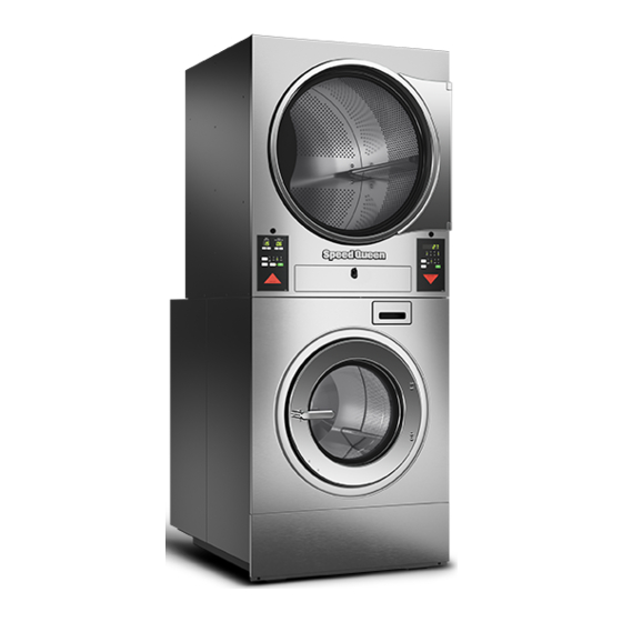
Stacked washer-extractor/ tumble dryer
Hide thumbs
Also See for HSA030N:
- Original instructions manual (64 pages) ,
- Re)programming manual (55 pages) ,
- Programming manual (54 pages)
Table of Contents
Advertisement
Stacked Washer-Extractor/
Stacked 30 Pound (13/13 Kilogram) Capacity
Stacked 50 Pound (22/22 Kilogram) Capacity
Original Instructions
Keep These Instructions for Future Reference.
CAUTION: Read the instructions before using the machine.
(If this machine changes ownership, this manual must accompany machine.)
Refer to Page 15 for Model Identification
www.alliancelaundry.com
Tumble Dryer
Designs 1 and 2
STX1C_SVG
Part No. F8690001ENR7
December 2021
Advertisement
Table of Contents

Related Manuals for Alliance Laundry Systems HSA030N

Summary of Contents for Alliance Laundry Systems HSA030N
- Page 1 Stacked Washer-Extractor/ Tumble Dryer Stacked 30 Pound (13/13 Kilogram) Capacity Stacked 50 Pound (22/22 Kilogram) Capacity Designs 1 and 2 Refer to Page 15 for Model Identification STX1C_SVG Original Instructions Keep These Instructions for Future Reference. CAUTION: Read the instructions before using the machine. (If this machine changes ownership, this manual must accompany machine.) Part No.
- Page 3 IMPORTANT: The tumble dryer is not to be used if in- dustrial chemicals have been used for cleaning. Units are IPx4 when enclosed per these instructions. © Copyright, Alliance Laundry Systems LLC - Part No. F8690001ENR7 DO NOT COPY or TRANSMIT...
- Page 4 DO NOT let children play on or in the dryer. W931 To reduce the risk of serious injury: Avoid contact with hot surfaces. In Australia and New Zealand: W927 © Copyright, Alliance Laundry Systems LLC - Part No. F8690001ENR7 DO NOT COPY or TRANSMIT...
- Page 5 Users of this product are cautioned not to make modifications or This device contains license-exempt transmitter(s)/receiver(s) changes that are not approved by Alliance Laundry Systems, that comply with Innovation, Science and Economic Develop- LLC. Doing so may void the compliance of this product with ap- ment Canada’s license-exempt RSS(s) standards.
- Page 6 Conformity which is available upon request. thorized to the radio or the antenna of the approved device. Alliance Laundry Systems products comply with the requirement TAIWAN of Article 12 as it can be operated in at least one Member State as...
- Page 7 The wash program recommended in this manual is for a nominal load at rated load capacity. Refer to programming manual for de- tails of wash program. © Copyright, Alliance Laundry Systems LLC - Part No. F8690001ENR7 DO NOT COPY or TRANSMIT...
- Page 8 NOTE: The referenced Environmental Protection Use Period Marking was determined according to normal oper- ating use conditions of the product such as temperature and humidity. This product under normal use, durable years of environmental protection is 15 years. © Copyright, Alliance Laundry Systems LLC - Part No. F8690001ENR7 DO NOT COPY or TRANSMIT...
-
Page 9: Safety Information
Save These Instructions continuously supervised. • Do not reach into the tumble dryer if the cylinder is revolving. • Read all instructions before using the tumble dryer. © Copyright, Alliance Laundry Systems LLC - Part No. F8690001ENR7 DO NOT COPY or TRANSMIT... -
Page 10: Important Safety Instructions (Washer-Extractor)
DOES NOT remove all elec- free from flammable and combustible products. Do not add trical power from tumble dryer. the following substances or textiles containing traces of the © Copyright, Alliance Laundry Systems LLC - Part No. F8690001ENR7 DO NOT COPY or TRANSMIT... - Page 11 Be sure water connections have a shut-off valve and that fill hose connections are tight. CLOSE the shut-off valves at the end of each wash day. © Copyright, Alliance Laundry Systems LLC - Part No. F8690001ENR7 DO NOT COPY or TRANSMIT...
-
Page 12: Safety Decals
3. Do not attempt to operate the machine if any of the following conditions are present: a. The door does not remain securely locked during the en- tire cycle. © Copyright, Alliance Laundry Systems LLC - Part No. F8690001ENR7 DO NOT COPY or TRANSMIT... -
Page 13: Table Of Contents
Required for IEC Models Only (Tumble Dryer)........... 55 © Copyright 2021, Alliance Laundry Systems LLC All rights reserved. No part of the contents of this book may be reproduced or transmitted in any form or by any means without the expressed written consent of the publisher. - Page 14 Thermal Overload Protector............... 85 Adjustments - Tumble Dryer..............86 Adjustments....................86 Gas Burner Air Shutter.................. 86 Airflow Switch .................... 87 Loading Door Switch..................87 Door Strike....................88 © Copyright, Alliance Laundry Systems LLC - Part No. F8690001ENR7 DO NOT COPY or TRANSMIT...
- Page 15 Manual Resettable Thermostat............... 88 Before You Call for Service..............89 Removing Machine from Service............90 Disposal of Unit..................91 © Copyright, Alliance Laundry Systems LLC - Part No. F8690001ENR7 DO NOT COPY or TRANSMIT...
-
Page 16: Introduction
VC - Touch Control, Single Coin Drop E - Electronic Coin Drop VX - Touch Control, Prep for Coin L - Prep for Central Pay Y - Prep for Card © Copyright, Alliance Laundry Systems LLC - Part No. F8690001ENR7 DO NOT COPY or TRANSMIT... -
Page 17: Contact Information
Alliance Laun- Alliance Laundry Systems dry Systems at +1 (920) 748-3950 for the name and address of Shepard Street the nearest authorized parts distributor. © Copyright, Alliance Laundry Systems LLC - Part No. F8690001ENR7 DO NOT COPY or TRANSMIT... - Page 18 Introduction P.O. Box 990 Ripon, WI 54971-0990 U.S.A. www.alliancelaundry.com Phone: +1 (920) 748-3121 Ripon, Wisconsin © Copyright, Alliance Laundry Systems LLC - Part No. F8690001ENR7 DO NOT COPY or TRANSMIT...
-
Page 19: Specifications And Dimensions
Tumble Dryer TUMBLE DRYER Cylinder Information Cylinder Size: 30.0 x 26.0 [762 x 660] 33.0 x 30.0 [838 x 762] Inch [mm] Table 1 continues... © Copyright, Alliance Laundry Systems LLC - Part No. F8690001ENR7 DO NOT COPY or TRANSMIT... - Page 20 3 Phase - 21 Not Applicable 1 Phase - 9 WASHER-EXTRACTOR Wash Cylinder Information Cylinder diameter, in. [mm] 24.0 [610] 26.3 [668] Table 1 continues... © Copyright, Alliance Laundry Systems LLC - Part No. F8690001ENR7 DO NOT COPY or TRANSMIT...
- Page 21 766 [200] 733 [200] Table 1 NOTE: All IEC machines are shipped with an adapter to convert the gas connection threads to BSPT (from NPT). © Copyright, Alliance Laundry Systems LLC - Part No. F8690001ENR7 DO NOT COPY or TRANSMIT...
-
Page 22: Cabinet Dimensions
Models 36.2 [920] 45.5 [1152] 2.5 [63] 23.9 [606] 31.4 [797] 79.7 [2023] 41.5 [1053] 51.3 [1302] 2.8 [70] 28.5 [724] 34.4 [875] 84.3 [2141] © Copyright, Alliance Laundry Systems LLC - Part No. F8690001ENR7 DO NOT COPY or TRANSMIT... -
Page 23: Front Machine Dimensions
Machine Dimensions, in. [mm] Models 64.0 [1625] 24.0 [610] 18.2 [462] 26.4 [669] 42.0 [1068] 67.0 [1703] 26.0 [660] 19.5 [496] 28.5 [724] 44.1 [1120] Table 3 © Copyright, Alliance Laundry Systems LLC - Part No. F8690001ENR7 DO NOT COPY or TRANSMIT... -
Page 24: Rear Machine Dimensions
8. Electric Models Machine Dimensions, in. [mm] Models 31.3 [794] 38.8 [986] 4.3 [108] 10.5 [267] 33.1 [841] 40.7 [1033] 4.5 [115] 10.7 [271] Table 4 © Copyright, Alliance Laundry Systems LLC - Part No. F8690001ENR7 DO NOT COPY or TRANSMIT... - Page 25 Specifications and Dimensions Models 36.1 [917] 38.1 [968] 69.1 [1755] 77.0 [1955] 38.2 [970] 40.2 [1021] 72.2 [1834] Not Applicable © Copyright, Alliance Laundry Systems LLC - Part No. F8690001ENR7 DO NOT COPY or TRANSMIT...
-
Page 26: Exhaust And Gas Connection Locations
83.6 [2123] 69.1 [1755] 68.3 [1735] Table 5 Models 1.7 [44] 37.5 [951] 4.2 [107] 36.8 [935] 4.1 [104] 43.6 [1108] 5.2 [132] 42.9 [1089] © Copyright, Alliance Laundry Systems LLC - Part No. F8690001ENR7 DO NOT COPY or TRANSMIT... -
Page 27: Mounting Bolt Hole Locations
Specifications and Dimensions Mounting Bolt Hole Locations Refer to Table 6 STX11N_SVG 1. Front of Mounting Bolt Template Figure 2 © Copyright, Alliance Laundry Systems LLC - Part No. F8690001ENR7 DO NOT COPY or TRANSMIT... - Page 28 10.5 [267] 12.5 [318] 23.5 [597] 23.626 [600] 0.188 [5] 1.187 [30] 28.938 [735] 32.5 [826] 29.69 [754] 33.54 [852] 0.641 [16] 0.641 [16] Table 6 © Copyright, Alliance Laundry Systems LLC - Part No. F8690001ENR7 DO NOT COPY or TRANSMIT...
-
Page 29: Floor Mounting Layout
Distance of machine base to edge of pad 4 [102] 3.99 [101] (minimum) Distance of machine base to edge of pad 1.27 [32] 0.95 [24] (minimum) Table 7 © Copyright, Alliance Laundry Systems LLC - Part No. F8690001ENR7 DO NOT COPY or TRANSMIT... - Page 30 Dimensional Clearances - Side-by-Side Mount, in. [mm] Description Distance to wall (minimum) 36.4 [925] 37.2 [945] Mounted without bases (minimum) 7.55 [192] 8.35 [212] Table 8 © Copyright, Alliance Laundry Systems LLC - Part No. F8690001ENR7 DO NOT COPY or TRANSMIT...
-
Page 31: Installation
If rear of machine or water supply is located in an area where it will be exposed to cold/freezing temperatures, provisions must be made to protect these water lines from freezing. © Copyright, Alliance Laundry Systems LLC - Part No. F8690001ENR7 DO NOT COPY or TRANSMIT... -
Page 32: Removing Dryer
[129 kg] and S50 models weighs335 lbs. [152 kg]. 1. Remove lint drawer. Refer to Figure 6 . STX13N 1. Lint Drawer Figure 6 © Copyright, Alliance Laundry Systems LLC - Part No. F8690001ENR7 DO NOT COPY or TRANSMIT... - Page 33 If you have trouble with Step 8, you may need to cut the tie and give slack to the harness. Refer to Figure 12 . © Copyright, Alliance Laundry Systems LLC - Part No. F8690001ENR7 DO NOT COPY or TRANSMIT...
- Page 34 Figure 14 9. Work strain relief out of oblong hole in top rear center pan. Set aside for reinstallation later. Refer to Figure 15 . © Copyright, Alliance Laundry Systems LLC - Part No. F8690001ENR7 DO NOT COPY or TRANSMIT...
- Page 35 STX30N Figure 19 13. Feed one or two tumble dryer harnesses up and out through holes in rear pan. Refer to Figure 20 . © Copyright, Alliance Laundry Systems LLC - Part No. F8690001ENR7 DO NOT COPY or TRANSMIT...
- Page 36 Reattach fill valve to valve panel and reattach valve panel onto back of machine. f. Reinstall all hardware: two L-brackets at rear of machine and two screws in lint compartment. © Copyright, Alliance Laundry Systems LLC - Part No. F8690001ENR7 DO NOT COPY or TRANSMIT...
-
Page 37: Single Machine Foundation Requirements
Thoroughness of detail must be stressed with all foundation work stallation based on consultations with a structural en- to ensure a stable unit installation, eliminating possibilities of ex- gineer. Alliance Laundry Systems stands behind all in- cessive vibration during extract. stallations meeting these specifications. For alternate... -
Page 38: Machine Mounting And Grouting
Distance between reinforcing bars (minimum) 12 [305] 12 [305] Length of reinforcing bar extending into existing 2.5 [64] 2.5 [64] floor (minimum) Table 10 Machine Mounting and Grouting © Copyright, Alliance Laundry Systems LLC - Part No. F8690001ENR7 DO NOT COPY or TRANSMIT... - Page 39 WARNING Crush hazard. To avoid personal injury and/or property damage, do not tip the machine more than 20 degrees in any direction. W1062 © Copyright, Alliance Laundry Systems LLC - Part No. F8690001ENR7 DO NOT COPY or TRANSMIT...
- Page 40 Cast-in-place Anchors (refer to Table 11 ) CHM2438N_SVG 1. Machine Frame Base 2. Grout 3. Anchor Bolt (minimum Grade 5 SAE rating) 4. Concrete 5. Edge of Pad Figure 28 © Copyright, Alliance Laundry Systems LLC - Part No. F8690001ENR7 DO NOT COPY or TRANSMIT...
-
Page 41: Drain Connection Requirements
A surge tank along with a sump pump should be used All drain systems must be vented to prevent an air lock or siphon- when gravity drainage is not possible. ing. © Copyright, Alliance Laundry Systems LLC - Part No. F8690001ENR7 DO NOT COPY or TRANSMIT... - Page 42 * Drain line must be vented to meet local plumbing codes. 1. Drain Hose 2. Drain Valve 3. Drain Tee 4. Overflow Hose 5. Vent Pipe* 6. Trap (as required by local codes) Figure 30 © Copyright, Alliance Laundry Systems LLC - Part No. F8690001ENR7 DO NOT COPY or TRANSMIT...
-
Page 43: Water Connection Requirements
AS/NZS 3500.I. Water Supply Information Specification Requirement Water inlet connection size, in. Thread pitch, GHT [BSPP] 3/4 x 11-1/2 [3/4 x Table 14 continues... © Copyright, Alliance Laundry Systems LLC - Part No. F8690001ENR7 DO NOT COPY or TRANSMIT... -
Page 44: Connect Inlet Hoses
Table 15 Suitable air cushions (risers) should be installed in supply lines to prevent “hammering.” Refer to Figure 31 . Alliance Laundry Systems, LLC ranges of front loading commer- PHM831N_SVG cial clothes washing machines have solenoid valves at the inlets. - Page 45 If additional hose lengths are needed or using hoses other than those supplied by manufacturer, flexible hoses with screen filters are required. © Copyright, Alliance Laundry Systems LLC - Part No. F8690001ENR7 DO NOT COPY or TRANSMIT...
-
Page 46: Plumbing Diagrams
Installation Plumbing Diagrams Side View (refer to Table 16 ) STX9N_SVG Figure 35 © Copyright, Alliance Laundry Systems LLC - Part No. F8690001ENR7 DO NOT COPY or TRANSMIT... - Page 47 Installation Rear View (refer to Table 16 ) STX10N_SVG 1. Vacuum Breaker Overflow Figure 36 © Copyright, Alliance Laundry Systems LLC - Part No. F8690001ENR7 DO NOT COPY or TRANSMIT...
-
Page 48: Chemical Injection Supply System
IMPORTANT: Water pressure must not exceed 40 psi [275 kPa]. Table 17 1. Drill through the ports on the chemical supply connector as needed for the external supply hoses. © Copyright, Alliance Laundry Systems LLC - Part No. F8690001ENR7 DO NOT COPY or TRANSMIT... - Page 49 Connection for Chemical Supply Hoses (refer to Figure 38 for detail of chemical supply connector) CHM2658N_SVG 1. Chemical Supply Connector 2. External Liquid Supply Connection Ports (13) Figure 37 © Copyright, Alliance Laundry Systems LLC - Part No. F8690001ENR7 DO NOT COPY or TRANSMIT...
- Page 50 Installation External Liquid Supply Connection Ports CHM2659_SVG 1. 3/8 inch port, O.D. 2. 1/2 inch port, O.D. Figure 38 © Copyright, Alliance Laundry Systems LLC - Part No. F8690001ENR7 DO NOT COPY or TRANSMIT...
-
Page 51: External Supplies
© Copyright, Alliance Laundry Systems LLC - Part No. F8690001ENR7 DO NOT COPY or TRANSMIT... -
Page 52: Chemical Injection Using External Ac Power Source
NOTE: An External AC Power Source is NOT provided by Alliance Laundry Systems. NOTE: Power for external supplies must not be derived from the high-voltage main power connection point. © Copyright, Alliance Laundry Systems LLC - Part No. F8690001ENR7 DO NOT COPY or TRANSMIT... -
Page 53: External Supply Signals
Figure 45 control. Refer to Figure 45 for Internal Supply Connection or and Figure 47 for External AC Connection. © Copyright, Alliance Laundry Systems LLC - Part No. F8690001ENR7 DO NOT COPY or TRANSMIT... -
Page 54: Before Placing Tumble Dryer Into Service
IMPORTANT: Remove tape from the lint panel safety switch before proceeding to the next step. Before Placing Tumble Dryer into Service 1. Ensure all panels and guards are in place. © Copyright, Alliance Laundry Systems LLC - Part No. F8690001ENR7 DO NOT COPY or TRANSMIT... -
Page 55: Required For Iec Models Only (Tumble Dryer)
• On front panel at the periphery of cylinder access opening • On electrical box cover(s) • On rear panel © Copyright, Alliance Laundry Systems LLC - Part No. F8690001ENR7 DO NOT COPY or TRANSMIT... -
Page 56: Exhaust Requirements - Tumble Dryer
Proper sized exhaust ducts are essential for proper operation. All elbows should be sweep type. Exhaust ducts must be assembled so the interior surfaces are smooth, so the joints do not permit the © Copyright, Alliance Laundry Systems LLC - Part No. F8690001ENR7 DO NOT COPY or TRANSMIT... -
Page 57: Individual Venting
NOTE: Inside of duct must be smooth. Do not use For maximum efficiency and performance, it is preferred to ex- sheet metal screws to join sections. haust tumble dryer(s) individually to the outdoors. © Copyright, Alliance Laundry Systems LLC - Part No. F8690001ENR7 DO NOT COPY or TRANSMIT... -
Page 58: Manifold Venting
= 14 ft. [4.3 m] + (2) 90° elbows T438i_SVG = 14 ft. [4.3 m] + 14 ft. [4.3 m] + 14 ft. [4.3 m] = 42 ft. [12.8 m] Figure 49 © Copyright, Alliance Laundry Systems LLC - Part No. F8690001ENR7 DO NOT COPY or TRANSMIT... - Page 59 NOTE: Table 19 represents tumble dryers with the same NOTE: Duct clean-out recommended every 6 feet [0.18 vent size. If multiple vent sizes are used, consult a lo- cal HVAC specialist. © Copyright, Alliance Laundry Systems LLC - Part No. F8690001ENR7 DO NOT COPY or TRANSMIT...
- Page 60 1. Outlet duct diameter = combined largest duct diameter of both sides 2. 45° typical Figure 51 Refer to Table 19 for measurements for each manifold. © Copyright, Alliance Laundry Systems LLC - Part No. F8690001ENR7 DO NOT COPY or TRANSMIT...
-
Page 61: Gas Requirements - Tumble Dryer
Use the individual man- ual shut-off valve from the gas supply piping system to protect the gas valve. © Copyright, Alliance Laundry Systems LLC - Part No. F8690001ENR7 DO NOT COPY or TRANSMIT... - Page 62 (tumble dryers, water heat- ers, space heaters, furnace, etc.): Maximum 13 in. w.c. Refer to Table Recommend- 11 in. w.c. Minimum 10 in. w.c. © Copyright, Alliance Laundry Systems LLC - Part No. F8690001ENR7 DO NOT COPY or TRANSMIT...
- Page 63 3B/P 42.5 57.5 27.5 2E(r) 2E(r)3+ 2E(r) 12.0 3+ (30/37) Bu- 30 (28-30) tane 3+ (30/37) Propane 12.0 2L3B/P 3B/P 30 (28-30) Table 20 continues... © Copyright, Alliance Laundry Systems LLC - Part No. F8690001ENR7 DO NOT COPY or TRANSMIT...
-
Page 64: How To Change Burner Orifice Size
If in doubt, the installer shall contact the supplier. Figure 52 How to Change Burner Orifice Size © Copyright, Alliance Laundry Systems LLC - Part No. F8690001ENR7 DO NOT COPY or TRANSMIT... - Page 65 1. Gas Shut-Off Valve (Ahead of pressure tap) (Shown in open position) (Not Supplied) 2. Pressure Tap 3. Gas Shut-Off Valve (Shown in closed position) (Not Supplied) 4. Specified Local Inlet Pressure Figure 53 © Copyright, Alliance Laundry Systems LLC - Part No. F8690001ENR7 DO NOT COPY or TRANSMIT...
-
Page 66: How To Adjust Gas Valve Governor/Regulator
Tumble Dryers are supplied from the factory for operation with natural gas categories 2H, 2E, 2L, 2E(LL), 2E(r), © Copyright, Alliance Laundry Systems LLC - Part No. F8690001ENR7 DO NOT COPY or TRANSMIT... -
Page 67: Adjusting Manifold Pressure For Natural Gas G20 Or G25
W924 3. Verify manifold pressure. Refer to How to Adjust Gas Valve Governor/Regulator and adjust as necessary. Adjusting Supply Pressure for L.P.G. G30 or G31 © Copyright, Alliance Laundry Systems LLC - Part No. F8690001ENR7 DO NOT COPY or TRANSMIT... -
Page 68: Gas Supply Pipe Sizing And Looping
Other gas using appli- ances should be connected upstream from loop. © Copyright, Alliance Laundry Systems LLC - Part No. F8690001ENR7 DO NOT COPY or TRANSMIT... -
Page 69: Low Pressure Gas Pipe Sizes
2-1/2 2-1/2 2-1/2 1,300,000 2-1/2 2-1/2 2-1/2 2-1/2 1,400,000 2-1/2 2-1/2 2-1/2 2-1/2 1,500,000 2-1/2 2-1/2 2-1/2 2-1/2 1,600,000 2-1/2 2-1/2 2-1/2 Table 21 continues... © Copyright, Alliance Laundry Systems LLC - Part No. F8690001ENR7 DO NOT COPY or TRANSMIT... - Page 70 3-1/2 For L.P. Gas, correct the total Btu/hr by multiplying it by 0.6. The answer is the equivalent Btu on the above chart. Table 21 © Copyright, Alliance Laundry Systems LLC - Part No. F8690001ENR7 DO NOT COPY or TRANSMIT...
-
Page 71: High Pressure Gas Pipe Sizes
140,000 160,000 180,000 200,000 300,000 400,000 500,000 600,000 700,000 800,000 900,000 1,000,000 1,100,000 1,200,000 1,300,000 1-1/4 1,400,000 1-1/2 1,500,000 1-1/4 1,600,000 1-1/4 Table 22 continues... © Copyright, Alliance Laundry Systems LLC - Part No. F8690001ENR7 DO NOT COPY or TRANSMIT... -
Page 72: High Altitude Burner Orifice Sizing
For proper operation at altitudes above 2,000 feet [610 m], the For IEC models, consult local gas supplier. gas burner orifice size must be reduced to ensure complete com- © Copyright, Alliance Laundry Systems LLC - Part No. F8690001ENR7 DO NOT COPY or TRANSMIT... - Page 73 2,001-4,000 0.0820 M401027 [610-1,220] [2.08] 4,001-6,000 0.0810 M401003 [ 1,221-1,830] [2.06] 6,001-8,000 0.0760 M401001 [ 1,831-2,440] [1.93] 8,001-10,000 0.0730 M401018 [ 2,441-3,050] [1.85] Table 23 © Copyright, Alliance Laundry Systems LLC - Part No. F8690001ENR7 DO NOT COPY or TRANSMIT...
- Page 74 M403017 [610-1,220] [2.37] 4,001-6,000 2.3 mm 0.0906 70070905 [ 1,221-1,830] [2.30] 6,001-8,000 0.0890 M406184 [ 1,831-2,440] [2.26] 8,001-10,000 0.0860 M401011 [ 2,441-3,050] [2.18] Table 24 © Copyright, Alliance Laundry Systems LLC - Part No. F8690001ENR7 DO NOT COPY or TRANSMIT...
-
Page 75: Electrical Requirements
The appliance must not be supplied through an ex- ternal switching device, such as a timer, or connect- ed to a circuit that is regularly switched on and off by a utility. W943 © Copyright, Alliance Laundry Systems LLC - Part No. F8690001ENR7 DO NOT COPY or TRANSMIT... -
Page 76: Wiring Diagram
All control types will consider a pulse valid if it is between 10 IMPORTANT: Alliance Laundry Systems warranty does and 1000 milliseconds in length, with a minimum of 25 millisec- not cover components that fail as a result of improper onds between pulses. -
Page 77: Service/Ground Location (Tumble Dryer)
Never attempt to connect a live circuit. W409R1 Service/Ground Location (Tumble Dryer) Model Heat Source Ground and Terminal Block Locations TMB2616N_SVG 1. Ground 2. Power Distribution Block Table continues... © Copyright, Alliance Laundry Systems LLC - Part No. F8690001ENR7 DO NOT COPY or TRANSMIT... -
Page 78: Grounding (Washer-Extractor)
“single phasing” and causing premature failure of the motor(s). • Electrical service must be connected using the appropriate permanent rigid metal conduit system. • Service conductors must be copper only. © Copyright, Alliance Laundry Systems LLC - Part No. F8690001ENR7 DO NOT COPY or TRANSMIT... -
Page 79: Electrical Specifications
Figure 58 NOTE: Electrical specifications below are subject to change without notice. Always refer to product serial plate for most current specifications of product being installed. © Copyright, Alliance Laundry Systems LLC - Part No. F8690001ENR7 DO NOT COPY or TRANSMIT... - Page 80 200-240 50-60 Refer to Fig- 14 [2.5] ure 58 L1, L2, L3 and ground 380-415 50-60 L1, L2, L3 and 14 [2.5] ground Table 26 © Copyright, Alliance Laundry Systems LLC - Part No. F8690001ENR7 DO NOT COPY or TRANSMIT...
- Page 81 14 [2.5] ure 58 F-speed 6 L1, L2, L3 and ground P ** 380-415 50-60 L1, L2, L3 14 [2.5] and ground Table 28 continues... © Copyright, Alliance Laundry Systems LLC - Part No. F8690001ENR7 DO NOT COPY or TRANSMIT...
- Page 82 58 F-speed 7 L1, L2, L3 V-speed 5 and ground F-speed 380-415 50-60 L1, L2, L3 V-speed 4 14 [2.5] and ground F-speed Table 29 © Copyright, Alliance Laundry Systems LLC - Part No. F8690001ENR7 DO NOT COPY or TRANSMIT...
-
Page 83: Input Power Conditioning
Refer to Electrical Specifications section for model-specific circuit break- er requirements. © Copyright, Alliance Laundry Systems LLC - Part No. F8690001ENR7 DO NOT COPY or TRANSMIT... -
Page 84: Single-Phase Connections
GFCI must be rated for 30mA or higher. Single-Phase Connections For single-phase input, connect L1, L2 and Ground and cap neu- tral as shown in Figure 60 . © Copyright, Alliance Laundry Systems LLC - Part No. F8690001ENR7 DO NOT COPY or TRANSMIT... -
Page 85: Phase Adder
IMPORTANT: Do not use a phase adder on any ma- chine. Thermal Overload Protector The inverter drive provides overload protection for the drive mo- tor. © Copyright, Alliance Laundry Systems LLC - Part No. F8690001ENR7 DO NOT COPY or TRANSMIT... -
Page 86: Adjustments - Tumble Dryer
5. After air shutter is adjusted for proper flame, tighten air shut- lows: ter adjusting screw securely. Refer to Figure 62 . 1. Remove the burner inspection hole plate. © Copyright, Alliance Laundry Systems LLC - Part No. F8690001ENR7 DO NOT COPY or TRANSMIT... -
Page 87: Airflow Switch
3. No Airflow to achieve proper actuation. 4. Air Shutter Adjusting Screw 5. Burner Inspection Hole Figure 63 © Copyright, Alliance Laundry Systems LLC - Part No. F8690001ENR7 DO NOT COPY or TRANSMIT... -
Page 88: Door Strike
1. To adjust, open door, loosen acorn nut, and turn door strike screw in or out as required. 2. Retighten acorn nut. TMB2677N_SVG 1. Door Strike Screw 2. Acorn Nut Figure 65 © Copyright, Alliance Laundry Systems LLC - Part No. F8690001ENR7 DO NOT COPY or TRANSMIT... -
Page 89: Before You Call For Service
Tumble dryer is in Cool Down Mode. • • Lint screen clogged. Clean lint screen. • • Exhaust duct to outside is blocked. Clean out. © Copyright, Alliance Laundry Systems LLC - Part No. F8690001ENR7 DO NOT COPY or TRANSMIT... -
Page 90: Removing Machine From Service
4. Turn off manual gas shut-off valve on machine. 5. Turn off steam supply external to machine. 6. Remove all electric, gas and steam connections. © Copyright, Alliance Laundry Systems LLC - Part No. F8690001ENR7 DO NOT COPY or TRANSMIT... -
Page 91: Disposal Of Unit
MIX1N_SVG Figure 66 © Copyright, Alliance Laundry Systems LLC - Part No. F8690001ENR7 DO NOT COPY or TRANSMIT...
Need help?
Do you have a question about the HSA030N and is the answer not in the manual?
Questions and answers
error code "EF-TS"