Belmont Medical Technologies CritiCool Service Manual
Thermoregulation
Hide thumbs
Also See for CritiCool:
- User manual (125 pages) ,
- Operational training (79 pages) ,
- User manual (115 pages)
Table of Contents
Advertisement
Advertisement
Table of Contents

Related Manuals for Belmont Medical Technologies CritiCool


Summary of Contents for Belmont Medical Technologies CritiCool
- Page 1 ® CritiCool Thermoregulation Service Manual FDT-200-000 Rev J English...
- Page 2 2514 AP The Hague The Netherlands Switzerland Authorized Representative: Medenvoy Switzerland Gotthardstrasse 28 6302 ZUG Switzerland © by Belmont Medical Technologies. All RIGHTS RESERVED. Registered trademarks are the intellectual property of their respective holders. BELMONT MEDICAL TECHNOLOGIES FDT-200-000 Rev J...
-
Page 3: Table Of Contents
Side View ...........................20 Rear Panel .........................20 Accessories ...........................22 Pre-installation Requirements ....................23 Space and Environmental Requirements ................23 Electrical Requirements .....................23 Inspection Prior to Unpacking ....................23 Unpacking the CritiCool Device .....................24 Assembling the Handle ......................25 Accessory Kits ........................26 BELMONT MEDICAL TECHNOLOGIES FDT-200-000 Rev J... - Page 4 TEC Controller Parts ......................51 Human Sensors (HS) Board ....................52 Removing the Human Sensors Board ................53 Human Sensors Board Parts....................54 Man-Machine (User) Interface (MMI) ..................55 FP Board ..........................56 Removing the FP Board .....................57 FP Board Parts ........................57 BELMONT MEDICAL TECHNOLOGIES FDT-200-000 Rev J...
- Page 5 Pump Parts ........................71 Pump Block Diagram ......................72 Pump Block Parts ......................72 Solenoid Bypass Valve ......................73 Water-In and Water-Out Connectors ..................73 Removing the Water-In and Water-Out Connectors ............73 Water Connector Parts .......................74 Self-Test on System Startup ....................75 BELMONT MEDICAL TECHNOLOGIES FDT-200-000 Rev J...
- Page 6 Calibration Tool Set: Verification and Calibration Units ............105 Temperature Calibration Unit (Part Number 017-00284) ............. 106 Digital Pressure Gauge (Part Number 017-00290) .............. 106 Installing the Digital Pressure Gauge ................107 TEC Verification Unit (Part Number 017-00189) ..............108 BELMONT MEDICAL TECHNOLOGIES FDT-200-000 Rev J...
- Page 7 CritiCool – Targeted Temperature Management ..............111 CritiCool Spare Parts List ....................112 Downloading Software to a PC .................... 127 Downloading Software to the CritiCool Device ..............127 Downloading the Color Display Panel Software ..............129 Instructions for Recycling..................... 132...
- Page 8 ® CritiCool Service Manual LIST OF FIGURES Figure 1: Labels on CritiCool Device ..................15 Figure 2: CritiCool device: Front View ..................19 Figure 3: CritiCool device: Side View ..................20 Figure 4: CritiCool device: Rear Panel ..................21 Figure 5: Unpacking the CritiCool Device ..................24 Figure 6: Assembling the Handle ....................25...
- Page 9 Figure 57: Surface Calibration Cable ..................108 Figure 58: Thermostat Verification Tool................... 109 Figure 59: PCB Extraction Tool ....................109 Figure 60: CritiCool Control Unit ..................... 111 Figure 61: Download Complete Message................128 Figure 62: CRC Number ......................129 Figure 63: Color Display Panel Software Download ..............129 Figure 64: Display Loader Window ..................
- Page 10 Table 2: Accessories .........................22 Table 3: 200-00300 CritiCool Adult Accessory Kit with Reusable Probes ........26 Table 4: 200-00310 CritiCool Adult Accessory Kit for Use With Disposable Temperature Probes ..............................26 Table 5: 200-00320 CritiCool Infant Accessory Kit with Reusable Probes .........27 Table 6: 200-00330 CritiCool Infant Accessory Kit for Use With Disposable Temperature Probes ............................27...
-
Page 11: Definitions
The system shuts down (halts) if any elements of the control mechanism fail. End of Service Life Policy Belmont Medical Technologies is committed to providing parts and service for all its medical equipment purchased from Belmont for 7 full years from original date of manufacture. -
Page 12: Intended Use
Testing After Servicing the System As a result of service or maintenance to CritiCool, the steps detailed in Chapter 9 PERIODIC MAINTENANCE should be performed in order to ensure that the system is operating normally. If the system is not due for full Periodic Maintenance, the steps related to thermal disinfection and water filter replacement may be omitted, since these steps do not test system performance. -
Page 13: Precautions
For details, see Chapter 10. Do not block the CritiCool device ventilation grilles. Air must be able to flow • freely in and out in order to keep the device cool. -
Page 14: Emc Safety
Service Manual EMC Safety ® For safe use of the CritiCool system, it is required to keep the CritiCool system at a safe distance from devices emitting radio frequency (RF). Improper Use WARNING! Improper use of the CritiCool system can lead to skin lesions, electrical hazards, and severe changes in body temperature. -
Page 15: Labels
This section provides details about the labels and symbols located on the exterior of the CritiCool device. CritiCool Device Labels Figure 1 shows the label and its location on the CritiCool device. Figure 1: Labels on CritiCool Device BELMONT MEDICAL TECHNOLOGIES... -
Page 16: Symbols
Table 1: Symbols Symbol Description CE mark of conformity AC Voltage Fuse The serial number for this product Catalogue number European Authorized Representative Switzerland Authorized Representative Caution Type BF equipment Recycle for WEEE Date of manufacture BELMONT MEDICAL TECHNOLOGIES FDT-200-000 Rev J... - Page 17 ® CritiCool Service Manual Symbol Description Name of manufacturer Do not push Refer to instruction manual Prescription use only BELMONT MEDICAL TECHNOLOGIES FDT-200-000 Rev J...
-
Page 18: Criticool System
The CritiCool system is composed of two elements: CritiCool device • The CritiCool device functions as a control unit and a cooling/heating pump which ® circulates water to a connected wrap applied to the patient called CureWrap The control unit constantly monitors the patient’s core temperature through specific sensors using a software driven temperature control algorithm to reach the desired set point temperature. -
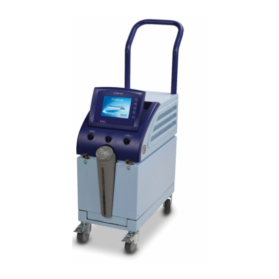
Page 19: External Features
CritiCool Service Manual External Features ® This section provides images of the front view, side view, and rear panel of the CritiCool device. Front View Figure 2 shows the front view of the CritiCool device with callouts of key components. -
Page 20: Side View
® CritiCool Service Manual Side View ® Figure 3 shows the side view of the CritiCool device with callouts of key components. Figure 3: CritiCool device: Side View Rear Panel ® Figure 4 shows the rear panel of the CritiCool device with callouts of key components. -
Page 21: Figure 4: Criticool Device: Rear Panel
® CritiCool Service Manual Figure 4: CritiCool device: Rear Panel BELMONT MEDICAL TECHNOLOGIES FDT-200-000 Rev J... -
Page 22: Accessories
The tubes are supplied as a paired unit with two male Quick Coupling 200-00147 CureWrap Connectors at the CritiCool device end and with three female Quick (2x3 way) Coupling Connectors at the wrap end. These connecting tubes are needed for the 500-03500 model CureWrap. -
Page 23: Pre-Installation Requirements
Space and Environmental Requirements The CritiCool device is supplied on a trolley as a mobile unit for user convenience. Locate the CritiCool device no less than 5 cm (2") from other objects to avoid impairing its ventilation. Consider the following dimensions when positioning the CritiCool device: 260 mm Wide x 625 mm Deep x 940 mm High / (10.23"... -
Page 24: Unpacking The Criticool Device
® CritiCool Service Manual Unpacking the CritiCool Device Figure 5 shows the proper sequence for unpacking the CritiCool. Figure 5: Unpacking the CritiCool Device BELMONT MEDICAL TECHNOLOGIES FDT-200-000 Rev J... -
Page 25: Assembling The Handle
(see Figure 6). 3. Press in and tighten the four captive thumb screws by hand (do not use force when tightening) to secure the handle and the top cover. Figure 6: Assembling the Handle BELMONT MEDICAL TECHNOLOGIES FDT-200-000 Rev J... -
Page 26: Accessory Kits
CritiCool Service Manual Accessory Kits ® NOTE: Refer to User's Manual for the equipment list specific to the CritiCool model. The CritiCool system includes one of the following accessories kits listed in the tables below. Reusable accessory kits 200-00300 and 200-00320 as well as reusable probes 014- 00005, 014-00020 and 014-00021 are not available in all parts of the world. -
Page 27: Moving The Unit
® CritiCool Service Manual Table 5: 200-00320 CritiCool Infant Accessory Kit with Reusable Probes Part Number Description Quantity 007-00169 Cork Ball Chain 0.25 meter 007-00170 Chain Connector Clear 4.5mm 014-00005 Reusable Core Temperature Sensor, Infant (10 FR) 014-00021 Reusable Surface Temperature Sensor 099-00065 Sensors Labels –... -
Page 28: Locking And Unlocking The Trolley Wheels
When the unit is stationary, the brakes must be in the locked position. Release the brakes only when transporting the unit. Storage Environment Store the CritiCool device in a clean and dry area according to the specifications in the CritiCool User Manual. NOTE: Disconnect connecting tubes and sensors when the device is not in use after draining the water.Packing Instructions for Transport... -
Page 29: Covers Assembly
® CritiCool Service Manual PANELS AND COVERS This chapter provides: ® Which elements of the CritiCool device can be accessed by each cover • The instructions for removal and re-assembly of each cover • Covers Assembly Key to the numbered items in Figure 8 on page 30:... -
Page 30: Figure 8: Removing Criticool Covers
® CritiCool Service Manual Figure 8: Removing CritiCool Covers BELMONT MEDICAL TECHNOLOGIES FDT-200-000 Rev J... -
Page 31: Removing The Covers And Handle
A drainage tube by means of a gutter that drains any fluids spilled on the MMI. • The fluid flows down through the drainage tube and exits at the bottom of the unit. Figure 9: MMI (Man-Machine (User) Interface) Cover BELMONT MEDICAL TECHNOLOGIES FDT-200-000 Rev J... -
Page 32: Figure 10: J4 On Controller Board
2. Screw the three hexagonal nuts and tighten with a torque of 80–90 Ncm. 3. Screw the two Allen head screws located behind the moving panel. 4. Re-assemble the top cover. 5. Re-assemble the handl J4 with ribbon cable attached Figure 10: J4 on Controller Board BELMONT MEDICAL TECHNOLOGIES FDT-200-000 Rev J... -
Page 33: Removing The Left And Ride Side Covers
The right side cover provides access to the following components: HCU (Heating Cooling Unit) • Water-out temperature and thermostat sensors • Solenoid by-pass valve • Figure 11: Removing the Left and Right Side Covers BELMONT MEDICAL TECHNOLOGIES FDT-200-000 Rev J... -
Page 34: Removing The Rear Cover
To re-assemble the rear cover: 1. Insert the lip at the top of the cover into the unit. 2. Tighten the two screws at the bottom of the cover. 3. Insert and tighten the self-tapping screw. BELMONT MEDICAL TECHNOLOGIES FDT-200-000 Rev J... -
Page 35: Removing The Bottom Front Cover
Phillips-head screws that secure the bottom front cover. 4. Unscrew the two 2mm Allen screws, one on each side of the cover. 5. Carefully place the CritiCool device on its side. 6. Unscrew the M4x8 Phillips-head screw (located at the bottom front edge of the trolley). -
Page 36: Removing The Handle
Removing the Handle The handle is shown in Figure 8 as callout 7. The handle (Figure 13) allows transport of the CritiCool device. It must be removed to enable removal of the top cover. Figure 13: Removing the Handle ... -
Page 37: Removing The Trolley
To remove the trolley: 1. Empty the water tank. See Draining the Water Tank on page 67. 2. Place the CritiCool device on its side carefully. 3. Unscrew the six Phillips-head screws and washers that secure the trolley to the main chassis. - Page 38 Service Manual ELECTRICAL SYSTEM This chapter describes the electric and electronic systems that control the functioning of the CritiCool system. WARNING! Detach the power cable before performing any maintenance or replacement procedures. Failure to do so could result in severe personal injury.
-
Page 39: Release Of Pcb Spacer Supports
After attaching the flat cable connector to the PCB, slide the bracket to lock the connectors together. To release the connectors, slide the bracket in the opposite direction. BELMONT MEDICAL TECHNOLOGIES FDT-200-000 Rev J... -
Page 40: Power Supply Transformer Assembly
1. Remove the handle and the top cover (see Chapter 5). 2. Remove the two Phillips-head screws above the ON/OFF switch panel in the rear of the CritiCool device. 3. Remove the controller board (see page 47). 4. Remove the four Phillips-head screws and washers. -
Page 41: Power Supply Transformer Assembly Parts
Table 8: Power Supply Transformer Assembly Parts Item No. Part No. Description Quantity 200-00059 (230/115V) or Power Supply Transformer Assembly 200-01100 (100V) 009-00006 Screw M4x8 Pan Phillips Stainless Steel 010-00013 Spring Washer M4 Stainless Steel BELMONT MEDICAL TECHNOLOGIES FDT-200-000 Rev J... -
Page 42: Controller Board
The controller board incorporates the power distribution circuit. Power from the transformer is rectified on the controller board and supplied to the: • FP Board • Human Sensors Board • The TEC control has its own power-rectifying circuit. BELMONT MEDICAL TECHNOLOGIES FDT-200-000 Rev J... -
Page 43: Table 9: Controller Board - Power On Leds On The Controller
Voltage RS 232 indication Com 5v LED 27 Communication LED 28 Communication LED 30 Indicates RS 232 cable connector Mloader LED 31 Indicates RS 232 Controller Loader cable Com IND LED D2 Fan Voltage type: CritiCool Green BELMONT MEDICAL TECHNOLOGIES FDT-200-000 Rev J... -
Page 44: Controller Board Connectors
Header 10 pin Power Supply Transformer Assembly connector Controller Board Fuses The CritiCool device controller board fuses are soldered to the controller board. You must replace a faulty board, including the fuses (instead of attempting to repair the board). BELMONT MEDICAL TECHNOLOGIES... -
Page 45: Controller Board Indicators
Controller Board Indicators Figure 19 and Figure 20 show the LEDs on the print side of the controller board and the components on the other side. Figure 19: Controller Board Component Placement - Print Side BELMONT MEDICAL TECHNOLOGIES FDT-200-000 Rev J... -
Page 46: Controller Board Status
The Controller Board function is controlled by two jumpers, JP10 and J11. JP11 controls the HCU fan speed and must be installed for proper CritiCool operation. JP10 is used to configure the board for either a color touch screen system when installed, or a monochrome system, non-touch screen when not installed. -
Page 47: Removing The Controller Board
3. With the extraction tool, release all seven PCB spacer supports. To remove the controller board, slide it out from the left side. NOTE: To reassemble the controller board, follow the procedure above in reverse order. BELMONT MEDICAL TECHNOLOGIES FDT-200-000 Rev J... -
Page 48: Controller Board Parts
® CritiCool Service Manual Controller Board Parts Table 12 lists the part numbers, description, and quantity for ordering controller board parts. Table 12: CritiCool Controller Board Parts Item Part No. Description Quantity Controller Board 300-00318 Color, Version 6.3 Assembly 004-00029... -
Page 49: Table 14: Tec Control Board - Connectors
Power to TECs on Right Side Controller JTAG Left Side, used in production. No active Molex 9 pin connection when installed in CritiCool. Controller JTAG Right Side used in production. No active Molex 9 pin connection when installed in CritiCool. -
Page 50: Removing Tec Control Board
® CritiCool Service Manual Removing TEC Control Board Figure 22 shows the components on each side of the TEC control board. Figure 22: TEC Control Board Components BELMONT MEDICAL TECHNOLOGIES FDT-200-000 Rev J... -
Page 51: Tec Controller Parts
Figure 23: TEC Controller Assembly Table 16 lists the part numbers for the TEC Controller. Table 16: TEC Controller Parts Item No. Qty. Part No. Description 300-R0017 TEC Controller Assembly 004-00030 PCB Spacer Support ECC-5 BELMONT MEDICAL TECHNOLOGIES FDT-200-000 Rev J... -
Page 52: Human Sensors (Hs) Board
All human sensor inputs are from thermistor temperature sensors. NOTE: Any faulty board must be replaced and not repaired. Figure 24 shows the human sensors board. Figure 24: Human Sensors Board BELMONT MEDICAL TECHNOLOGIES FDT-200-000 Rev J... -
Page 53: Removing The Human Sensors Board
0.25” stereo socket SURFACE input signal Header 2 Water-out temperature input signal Header 2 Water-in temperature input signal Header 2 Thermostat input signal Removing the Human Sensors Board Figure 25 shows the Human Sensors board assembly. BELMONT MEDICAL TECHNOLOGIES FDT-200-000 Rev J... -
Page 54: Human Sensors Board Parts
Human Sensors Board Parts Table 19 lists and describes the Human Sensors board parts. Table 19: Human Sensors Board Parts Item No. Qty. Part No. Description 300-R0016 Human Sensor Board Part of 300-R0016 Nut Sensor Socket BELMONT MEDICAL TECHNOLOGIES FDT-200-000 Rev J... -
Page 55: Man-Machine (User) Interface (Mmi)
Part No. Description CritiCool Top Panel Assembly (Display and Cover) 200-00240 (version 1.7) NOTE: Make sure to provide the desired language of the CritiCool Display to your Belmont Customer Service Representative when ordering 200-00240. BELMONT MEDICAL TECHNOLOGIES FDT-200-000 Rev J... -
Page 56: Fp Board
The Pressure Sensor is indicated in the Technician Mode screen as PresIn and the Pressor Sensors on the right is indicated in the Technician Mode screen as PresEx. Figure 27: FP Board BELMONT MEDICAL TECHNOLOGIES FDT-200-000 Rev J... -
Page 57: Removing The Fp Board
To re-assemble the FP board, follow the above directions in reverse order. FP Board Parts Table 21 lists the FB board parts. Table 21: FP Board Parts Item No. Qty. Part No. Description 300-R0015 FP Board 004-00031 PCB Spacer Support LCC-10 BELMONT MEDICAL TECHNOLOGIES FDT-200-000 Rev J... -
Page 58: Heating Cooling Unit (Hcu)
HCU. Figure 29 shows the HCU assembly and Table 22 lists its part number. Figure 29: HCU Assembly Table 22: HCU Assembly Part Number Item No. Qty. Part No. Description 200-R0054 HCU Assembly BELMONT MEDICAL TECHNOLOGIES FDT-200-000 Rev J... -
Page 59: Z Heat Exchanger
Service Manual Z Heat Exchanger There are four Z heat exchangers on each side of the CritiCool device. Water flows from the water tank, through the filter, through the pump, and through each set of the Z heat exchangers. The water is either heated or cooled in the Z heat exchanger by the thermal exchange units according to the demands of the system. -
Page 60: Fan
Figure 31: Removing the HCU To remove the HCU: NOTE: Before you start, place a cloth on a flat surface. Place the CritiCool device on its side on the cloth to prevent damage. 1. Remove the handle and the top cover (see Chapter 5). -
Page 61: Hcu Parts
Fast Acting fuse and a LED for the pump. The pump works on 12V (Machine Version 04, 05) and 10V (Machine Version 03). The pump operates at 1.8 bar for two minutes before being stopped at system halt. For instructions on removing the pump, see page 70. BELMONT MEDICAL TECHNOLOGIES FDT-200-000 Rev J... -
Page 62: Solenoid Bypass Valve
Disconnect the electrical control connection from the lower part of the solenoid with a bulldog Phillips screwdriver. Unscrew the two Phillips screws that secure the Solenoid Valve Bracket from the front of the CritiCool device. NOTE: To re-assemble the Solenoid Bypass Valve, follow the above directions in reverse order. -
Page 63: Thermistors
To reassemble the new Water-out thermostat thermistor: 1. Perform the same procedure in reverse order. 2. Fill the water tank and check for water leakage. 3. Replace the right side cover, top cover, and handle. BELMONT MEDICAL TECHNOLOGIES FDT-200-000 Rev J... -
Page 64: Replacing The Water-In Thermistor
During self-test and other cases: ADD WATER • After emptying the water tank: TANK IS EMPTY • Figure 34: Float Electrical Connections BELMONT MEDICAL TECHNOLOGIES FDT-200-000 Rev J... - Page 65 • procedures. Failure to do so could result in severe personal injury. This chapter describes the hydraulic system of the CritiCool device. The hydraulic system circulates water from the water tank through a filter, pump, heating/cooling elements, solenoid bypass valve, wrap, and back to the water tank.
-
Page 66: Figure 35: Hydraulic System
® CritiCool Service Manual The CritiCool device hydraulic system is pictured below in a block diagram. Figure 35 lists and describes the block diagram elements. Table 25 lists and describes the block diagram elements. Figure 35: Hydraulic System Table 25: Hydraulic System - Block Diagram Item No. -
Page 67: Water Tank Assembly
Water Out connecting tube (see Figure 36). Figure 36: Connecting Tubes and Special Male Connector 5. Allow the excess water to drain into a receptacle, pail or sink. 6. When the water finishes draining, turn the CritiCool device OFF. BELMONT MEDICAL TECHNOLOGIES FDT-200-000 Rev J... -
Page 68: Removing The Water Tank
Figure 37: Filter Replacing the Filter Replace the filter at least once per year. Filter replacement can be performed by the hospital personnel trained by Belmont Medical Technologies. NOTE: An additional filter is provided in the accessory box. BELMONT MEDICAL TECHNOLOGIES... -
Page 69: Removing The Filter
CritiCool Service Manual Removing the Filter Figure 38 shows the location and position of the filter in the CritiCool device. To remove the filter: 1. Drain the water tank (see page 67). 2. Remove the rear cover (see Chapter 5). -
Page 70: Pump
The pump is digitally controlled from the Controller board and is powered by 12VDC. Removing the Pump WARNING! You must drain the water tank before removing the pump. For instructions, see Draining the Water Tank on page 67. Figure 39: Removing the Pump BELMONT MEDICAL TECHNOLOGIES FDT-200-000 Rev J... -
Page 71: Pump Parts
5. Loosen the four pump screws leaving them in their rubber washers. These rubber washers are shock absorbers for the pump. 6. Slide the pump out of the CritiCool device. NOTE: To re-assemble the pump, follow the above procedure in reverse order. -
Page 72: Pump Block Diagram
Table 28 lists and describes the pump parts. Table 28: Pump Block Parts Item Part No. Description Qty. 200-00115 Pump Assembly 002-00027 Quick Angle Connector for Tube 8mm 005-00156 Connector Male 3-pin Crimp Panel Mount 005-00159 Pin Female Crimp 16 AWG BELMONT MEDICAL TECHNOLOGIES FDT-200-000 Rev J... -
Page 73: Solenoid Bypass Valve
Controller board. Water-In and Water-Out Connectors Removing the Water-In and Water-Out Connectors Figure 41 shows how to access and remove the connectors. Figure 41: Removing the Water-In and Water-Out Connectors BELMONT MEDICAL TECHNOLOGIES FDT-200-000 Rev J... -
Page 74: Water Connector Parts
3. Disconnect the 8mm flow tube from the back of the Water-Out connector (#3 in Figure 41). 4. Unscrew the two Phillips screws from the water bracket. 5. Remove the Water-Out connector from the CritiCool device. To remove the Water-In assembly: 1. Remove the handle and the top cover. -
Page 75: Self-Test On System Startup
This chapter provides information about the self-test that runs upon system startup, the CritiCool system’s safety algorithm, and the Technician mode error messages. Self-Test on System Startup On startup, the system performs a self-test to verify that the CritiCool device is functioning properly. The self-test includes the following: Screen and buzzer test •... -
Page 76: Halt Conditions
CritiCool Service Manual Halt Conditions Several conditions require you to disable the CritiCool device to prevent possible hazard to the patient or to the operator. Table 30 lists and describes the Halt messages. Halt messages provide information in cases that cause the system to shut down. - Page 77 5. Replace the FP board. 6. Replace Controller board. Halt 18 System detected a problem in Self- 1. Perform SW download Please Restart Test with Default data (memory of procedure. the system) 2. Replace Controller board. BELMONT MEDICAL TECHNOLOGIES FDT-200-000 Rev J...
-
Page 78: Technician Mode Error Messages
Check wrap (pressure is higher than 0.8 bar) 00000400 Connect core sensor to the CritiCool device 00000800 Wrong core sensor is inserted to the CritiCool device socket 00001000 Connect surface sensor to the CritiCool device 00002000 Wrong surface sensor is inserted to the CritiCool device socket... - Page 79 Electromagnetic interference in the water in sensor signal reading 01000000 Electromagnetic interference in the water out sensor signal reading 02000000 Core less than 30°C 04000000 Difference between SetPoint and Core more than 2°C 08000000 Difference between SetPoint and Core more than 0.8°C BELMONT MEDICAL TECHNOLOGIES FDT-200-000 Rev J...
-
Page 80: Overview Of The Periodic Maintenance Procedures
Technologies for calibration. Inform Belmont Medical Technologies of checkup inspections by providing: • ® o The serial number, model number and software version of the CritiCool device o Detailed maintenance report WARNINGS! The repair and servicing of the CritiCool system should be performed •... -
Page 81: Technician Mode
Service Manual Technician Mode Periodic Maintenance and System Tests are performed while the CritiCool is in Technician mode. This mode displays the readings of all the sensors, system parameters, pressure and Core out calibration, as well as device status information and error codes that are necessary in the analysis and correction of failure. -
Page 82: Table 32: Technician Mode Screen - Tab 1 Components
Denotes if the pump is operating Wrap: CritiCool device pumps water to the Garment WaterPass Tank: The CritiCool device is on bypass with no water flow to the garment. This function is used to switch OFF the heating/cooling elements TECs (On/Off) when checking water temperature sensors. -
Page 83: Figure 43: Technician Mode Screen - Tab 2
Software version number of machine and display Total time in hours and minutes since the last time the counter Total Work Time was reset. Software confirmation number (Cyclic Redundancy Check) indicating a successful download BELMONT MEDICAL TECHNOLOGIES FDT-200-000 Rev J... -
Page 84: Entering Technician Mode
Verification procedures listed in Chapter 9 are performed while the CritiCool device is in Technician Mode. To enter the Technician Mode on Color CritiCool Machine: 1. Turn the CritiCool device ON. 2. Wait for Self-Test to finish or skip to OPERATION by pressing the Operate button. -
Page 85: Performing Periodic Maintenance Verification Tests
Completing the Periodic Maintenance Form The top of the Periodic Maintenance Form is shown below. The following information is found on the back of the device on the CritiCool label. (See Figure 1 on page 15). P/N = Part Number (for example, 200-00236) •... -
Page 86: Water Filter And Air Intake Maintenance
The air inlet grilles are on the underside of the CritiCool. Be sure to clean both the right and left side. Use a vacuum, soft cloth, or soft brush to clear away any accumulated dirt. -
Page 87: Verifying Water Temperature Sensors
7. Enter the Technician screen with password 2223 and press OK. These settings are intended to simulate the patient temperature of 38.0°C on the CritiCool system and with the desired set point of 39.8°C. With these settings, the CritiCool device should heat at its full capacity. -
Page 88: Table 35: Verification Form - Water Temperature Sensors
Technician Mode screen in the Win and Wout columns on the report. 13. Turn the CritiCool device OFF. You have completed the Water Temperature sensors verification tests. Summarize the verification results and check to see that they are within the allowable tolerance (Table 35). -
Page 89: Verifying The Thermostat
(see Figure 45). Figure 45: Thermostat Socked on Human Sensors Board 4. If the CritiCool device remains in normal operation in this position after 30 seconds, disconnect the Thermostat Verification Tool (see Figure 46) from the Human Sensors board. -
Page 90: Verifying The Pressure
Perform the following test quickly after disconnecting connector J3. 6. Remove the cable connected to connector J3 (FUNK 2) on the Controller board located to the right of the RS-232 cable when facing the right side of the CritiCool device (refer to the Figure 20 on page 46). -
Page 91: Figure 47: Fp Pressure Board
Verification form. NOTE: If either Pressure is out of tolerance, you must replace the FP board. If the verification tests passed, proceed to Verifying the TECs Electrical Current on page BELMONT MEDICAL TECHNOLOGIES FDT-200-000 Rev J... -
Page 92: Verifying The Tecs Electrical Current
48) and with the Temperature Calibration Unit. WARNING! Turn the CritiCool device OFF before connecting or disconnecting cables to the TEC control board. Failure to do so can result in a severe electric shock. Figure 48: TEC Current Verification Unit... - Page 93 7. Connect the core sensor cable from the Temperature Calibration Unit to the Core sensor socket on the CritiCool device and set the calibration unit to 38°C. 8. Adjust the set-point temperature to 39.8°C. The system heats up to 40.8°C Water-out.
- Page 94 7. Connect the core sensor cable from the Temperature Calibration Unit to the Core sensor socket on the CritiCool device and set the calibration unit to 38°C. 8. Adjust the set-point temperature to 39.8°C. The system heats up to 40.8°C Water-out.
-
Page 95: Verifying Fan Function
With the unit powered on and the top cover removed, check for air movement exiting the top of both the Left and Right HCUs. Complete the section Fan’s Test on the Periodic Maintenance Form in Chapter 14 (shown below). BELMONT MEDICAL TECHNOLOGIES FDT-200-000 Rev J... -
Page 96: Performing A Self-Cleaning Procedure
® CritiCool Service Manual Performing a Self-Cleaning Procedure The purpose of the Self-Cleaning procedure is to remove biofilm in the CritiCool system using thermal disinfection. The procedure includes: 1. Water heating up to 70ºC 2. Water circulation internally and externally 3. -
Page 97: Performing The Self Cleaning Procedure
If there is any hot water leakage or burst, do not touch the machine. Disconnect the power cable from the wall and wait until the water reaches room temperature before trying to fix the problem. BELMONT MEDICAL TECHNOLOGIES FDT-200-000 Rev J... -
Page 98: Checking For Water Leakage
CritiCool Service Manual Checking for Water Leakage Dry the area around the CritiCool device. While running the system at high pressure, check all tubes for water leakage. Reinstall all covers. To test for leaks after Thermal Disinfection: 1. Remove the handle, top cover, left side cover and right side covers (see Chapter 2. -
Page 99: Figure 49: Leakage Test Equipment Connections
The external grounding may be placed in one of the following locations (Figure 50): RS232 Stud • On the metal side of the trolley wheel • On the stud of the rear cover • BELMONT MEDICAL TECHNOLOGIES FDT-200-000 Rev J... -
Page 100: Figure 50: Grounding Locations On Device
1. Connect the GND wire (from the red terminal) to the metal of the trolley wheel. 2. Press Print Header. 3. Press Protective Earth Resistance. 4. Verify that the test current is: 25A. NOTE: The Resistance limit should always be 0.1[Ohm]. The result should be under 0.1[Ohm]. BELMONT MEDICAL TECHNOLOGIES FDT-200-000 Rev J... -
Page 101: Halt Messages
Service Manual TROUBLESHOOTING This section provides information and instructions for troubleshooting system messages. WARNING! The repair, calibration, and servicing of the CritiCool System should be performed only by Belmont Medical Technologies or authorized agents of Belmont Medical Technologies. Halt Messages Halt messages provide information in case of problems that cause the system to shut down. - Page 102 Halt 8 Replace Water in thermistor Replace HS board Check for tubes kinked System detected Check pressure verification points overpressure Check FP harness Halt 13 Check/Replace FP board Check the Solenoid Valve Replace controller board BELMONT MEDICAL TECHNOLOGIES FDT-200-000 Rev J...
-
Page 103: Text Messages
Replace surface sensor with the one supplied with the system Use a new surface sensor Check HS board and harness CONNECT No core sensor detected Replace core sensor CORE SENSOR Check HS board and harness BELMONT MEDICAL TECHNOLOGIES FDT-200-000 Rev J... - Page 104 Replace MMI (see ELECTRICAL SYSTEM) Faulty controller board-MMI flat cable No display upon Faulty FP board Check fuse F6 on controller board startup FP board and MMI, sharing Replace FP board the same line Replace MMI BELMONT MEDICAL TECHNOLOGIES FDT-200-000 Rev J...
-
Page 105: Calibration Tool Set: Verification And Calibration Units
• in Chapter 9 Standard tools for normal maintenance • The calibration test for the Belmont Medical Technologies Temperature • Calibration Unit Calibration Tool Set: Verification and Calibration Units Verification is executed by means of the Calibration Toolset while operating in Technician mode. -
Page 106: Temperature Calibration Unit (Part Number 017-00284)
CritiCool Service Manual Temperature Calibration Unit (Part Number 017-00284) Belmont Medical Technologies supplies the TP400 (Figure 51). Figure 51: Temperature Simulator FOGG TP 400 (Part Number 017-00284) Digital Pressure Gauge (Part Number 017-00290) Belmont Medical Technologies supplies the Digital Pressure Gauge (Figure 52). -
Page 107: Installing The Digital Pressure Gauge
The labels on the panel indicate where to connect the tubes. Figure 53: Water-Out Connection (Left) and Water-In Connection (Right) Once connected, the pressure gauge is ready to use, as shown in Figure 54. Figure 54: Digital Pressure Gauge Connected BELMONT MEDICAL TECHNOLOGIES FDT-200-000 Rev J... -
Page 108: Tec Verification Unit (Part Number 017-00189)
The TEC Current Verification Unit (Figure 55) tests the current sent to the TECs on both sides of the CritiCool device from the TEC control board. The TEC Current Verification Unit has two cables. The cable with the plug is inserted to connectors J1 and J2L of the TEC current board. -
Page 109: Thermostat Verification Tool (Part Number 017-00229)
Service Manual Thermostat Verification Tool (Part Number 017-00229) The Thermostat Verification tool tests the tolerance of the thermostat in the CritiCool device. The tool has two sides, both with two-pin Molex connector. Each side is labeled on the main wire. -
Page 110: Standard Tools
® CritiCool Service Manual Standard Tools The following lists the standard tools needed to perform service procedures and tests on the CritiCool system: Crescent wrenches • Large long-nosed pliers • Small long-nosed pliers • Scissors • Retractable utility knife •... -
Page 111: Disclaimer
CritiCool Service Manual SPARE PARTS LIST This chapter lists and describes the spare parts for the CritiCool device. Disclaimer Due to continuing product innovation, the parts list is subject to change without notice. Spare parts pricing is provided by Belmont Medical Technologies Customer Service. -
Page 112: Criticool Spare Parts List
® CritiCool Service Manual CritiCool Spare Parts List Table 40 lists, describes, and shows a photo of the spare parts list for the CritiCool system. Table 40: CritiCool Spare Parts List Part Number Description Image 300-00318 CritiCool Controller Board, Version 6.3... - Page 113 ® CritiCool Service Manual Part Number Description Image 200-00145 CritiCool Top Cover 007-00352 CritiCool Front Lower Cover 200-00146 CritiCool Rear Cover 007-00365 CritiCool Handle 200-00141 CritiCool Trolley Assembly BELMONT MEDICAL TECHNOLOGIES FDT-200-000 Rev J...
- Page 114 CritiCool Service Manual Part Number Description Image 300-R0017 TEC Control Board (top and bottom shown in images) 300-R0016 Human Sensor Board (top and bottom shown in images) 300-R0015 Flow & Pressure Board 200-00115 Pump BELMONT MEDICAL TECHNOLOGIES FDT-200-000 Rev J...
- Page 115 ® CritiCool Service Manual Part Number Description Image 200-00078 Solenoid Valve Assembly 200-R0054 Heating & Cooling Unit Assembly (HCU) 200-00104 Water Tank Assembly Transformer Assembly 200-00059 230/115V 200-01100 100V BELMONT MEDICAL TECHNOLOGIES FDT-200-000 Rev J...
- Page 116 Part Number Description Image 200-R0130 Filter 006-00002 Power Entry Module (Line Filter) 300-R0098 Controller Board— TEC Control Board Harness X 2 300-00102 Transformer—TEC Control Board Harness X 2 300-R0100 Controller Board— Human Sensor Board Harness BELMONT MEDICAL TECHNOLOGIES FDT-200-000 Rev J...
- Page 117 ® CritiCool Service Manual Part Number Description Image 300-R0099 Controller Board— Flow & Pressure Board Harness 300-R0101 Controller Board— RS-232 Connector Harness 300-R0050 Main Harness Right Side 300-R0051 Main Harness Left Side BELMONT MEDICAL TECHNOLOGIES FDT-200-000 Rev J...
- Page 118 ® CritiCool Service Manual Part Number Description Image 300-R0091 Level Sensor Harness 300-R0080 Controller Board— Pump Harness 007-00049 Trolley Front Wheel with Lock 007-00047 Trolley Rear Wheel BELMONT MEDICAL TECHNOLOGIES FDT-200-000 Rev J...
- Page 119 ® CritiCool Service Manual Part Number Description Image 200-00108 Level Switch Assembly 200-00097 Water Out/In Female Connector 200-00121 Service Set of Screws 200-00119 Service Tubing Kit BELMONT MEDICAL TECHNOLOGIES FDT-200-000 Rev J...
- Page 120 ® CritiCool Service Manual Part Number Description Image 200-00109 Connecting Water Tubes (2x2 Way) 200-00147 Connecting Water Tubes (2x3 Way) 200-00069 Buffer Tube 200-00181 Bypass Tube without Thermocouple 200-00096 Bypass Tube with Thermocouple BELMONT MEDICAL TECHNOLOGIES FDT-200-000 Rev J...
- Page 121 Quick Connector T- 8 x 6 x 8 014-00020 Reusable Core Temperature Sensor – Grey 014-00021 Reusable Surface Temperature Sensor – Green 014-00028 Core Sensor Adaptor Cable for Disposable Sensors 014-00129 Surface Sensor Adaptor Cable (RJ Green) for Disposable Sensors BELMONT MEDICAL TECHNOLOGIES FDT-200-000 Rev J...
- Page 122 ® CritiCool Service Manual Part Number Description Image 014-00005 Reusable Infant Core Sensor (Grey) 014-00116 Power Cord 115V 014-00117 Power Cord 230V EU 014-00019 Power Cord 100V BELMONT MEDICAL TECHNOLOGIES FDT-200-000 Rev J...
- Page 123 ® CritiCool Service Manual SERVICE CALL FORM To receive our current technical assistance / service request form, please email: techservice@belmontmedtech.com. BELMONT MEDICAL TECHNOLOGIES FDT-200-000 Rev J...
- Page 124 ® CritiCool Service Manual PERIODIC MAINTENANCE FORM This chapter provides the Periodic Maintenance form. BELMONT MEDICAL TECHNOLOGIES FDT-200-000 Rev J...
- Page 125 ® CritiCool Service Manual BELMONT MEDICAL TECHNOLOGIES FDT-200-000 Rev J...
- Page 126 ® CritiCool Service Manual BELMONT MEDICAL TECHNOLOGIES FDT-200-000 Rev J...
-
Page 127: Downloading Software To A Pc
Downloading the software requires the serial cable (300-00113) between the device and the host PC. To download the CritiCool software to the device: 1. Do NOT turn on the CritiCool until instructed to do so in Step 16. 2. Double-click My Computer. 3. Double-click local drive C: 4. -
Page 128: Figure 61: Download Complete Message
14. Click OK and verify that a File Download window is displayed. 15. Verify that download serial cable is connected between the PC and the machine. 16. Turn the CritiCool machine ON. 17. Click Start to start the download process. During the download, a progress indicator appears in the Download window. -
Page 129: Downloading The Color Display Panel Software
Downloading the Color Display Panel Software To download the Color Display Panel software: 1. Connect one side of the 300-00112 download cable to the CritiCool and the other side to the PC serial port, according to the following diagram. -
Page 130: Figure 64: Display Loader Window
6. Connect the serial cable "Display Loader Cable" from COM connector on PC to the RS- 232 connection on the back of the CritiCool. Please note the labels on the cable and take care to connect the correct cable ends to each device, the PC and the CritiCool serial port. - Page 131 ® CritiCool Service Manual At the end of the download process, the following message appears. NOTE: Versions reported may differ from figure below. Message should reference intended uploaded software version. BELMONT MEDICAL TECHNOLOGIES FDT-200-000 Rev J...
-
Page 132: Instructions For Recycling
The following table lists and describes the components in the CritiCool device that should be safely removed before recycling. It also includes their relative weight and recycling information. -
Page 133: Table 41: Recycling Information
CFCs [Refrigerator gases] External electric cables Accessories Circuit boards 960gr Liquid Crystal Displays 185gr The fluorescent coating in cathode ray tubes General Material – Not required to remove Plastics ABS/PC 2645gr Metal 30.3Kg Internal Cables 380gr BELMONT MEDICAL TECHNOLOGIES FDT-200-000 Rev J...
Need help?
Do you have a question about the CritiCool and is the answer not in the manual?
Questions and answers