Table of Contents
Advertisement
Quick Links
Advertisement
Table of Contents
Troubleshooting

Related Manuals for Belmont Medical Technologies HYPERTHERMIA PUMP


Summary of Contents for Belmont Medical Technologies HYPERTHERMIA PUMP
- Page 1 ™ HYPERTHERMIA PUMP OPERATOR’S MANUAL...
- Page 2 ™ HYPERTHERMIA PUMP OPERATOR’S MANUAL All service calls & questions should be directed to: 780 BOSTON ROAD BILLERICA, MA 01821, USA USA: 855.397.4547 T: 866.663.0212 Worldwide: +1.978.663.0212 F: 978.663.0214 TECHNICAL SUPPORT CAUTION: Federal law (USA) restricts this device to sale by USA: 855.397.4547...
-
Page 3: Table Of Contents
Page No. Chapter 1: Introduction – System Overview Introduction ........................1-1 Indications for Use ......................1-1 Contraindications ......................1-1 ™ Overview of the Hyperthermia Pump ................1-2 Control Panel: Display and Keys ..................1-4 Vacuum Regulator ......................1-4 Ordering Information ....................1-5 Chapter 2: Operation Introduction ........................2-1 Step-by-Step Operating Procedures ................2-2... - Page 4 Page No. Pressure Control ..................2-13 Vacuum Control ..................2-13 Automatic Air Purging ................2-13 End of Procedure .................... 2-13 Accidental Power Off ..................2-14 Battery Operation Screen ................2-14 CHAPTER 3: ALARMS AND TROUBLESHOOTING GUIDE Introduction ........................3-1 A. Operational Alarms ....................3-1 Air Detection .....................3-1 Door Open ......................3-2 Fluid Out ......................3-2...
- Page 5 Page No. B. Service and Preventive Maintenance Schedule ............4-5 Schedule 1 ......................4-5 Schedule 2 ......................4-5 C. Routine Maintenance ....................4-6 Clean and/or Disinfect Exterior ..............4-6 Fluid Out and In-Line Air Detectors ............4-6 Power Cord ...................4-6 Temperature Probes ................4-6 Fan Guards ...................4-6 Vacuum Trap ..................4-6 Seals .....................4-7 Instrument Door and Ceramic Disks ............4-7...
-
Page 6: Chapter 1: Introduction - System Overview
The other two (2) temperature probes are supplied as part of the Hyperthermia Pump™ Procedure Kit, (REF 902-00045) for optional use with the location to be determined by the physician. The use of temperature probes is optional. -
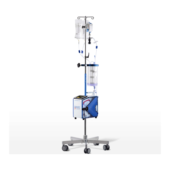
Page 7: Overview Of The Hyperthermia Pump
The complete system consists of the Control System, which is mounted on an IV pole, ™ and the System Disposable Set. The Hyperthermia Pump can be used only with the supplied disposables. The Disposable Set is preconnected and has a sterile fluid path. It is intended for single patient use only. -
Page 8: Control Panel: Display And Keys
Chapter 1: System Overview Three (3) disposable set options are available: Single Reservoir with Straight Inflow/Outflow (page 3), Single Reservoir with Straight Inflow/Bifurcated Outflow Patient Line (page 3), and Single Reservoir with two-Inflow and two-Outflow Patient Line (page 2). Single Reservoir, 4.4 Liter, with Straight Inflow/Straight Outflow Patient Line Single Reservoir, 4.4 Liter, with Straight Inflow/Bifurcated Outflow Patient Line CONTROL PANEL: DISPLAY AND KEYS The control panel consists of the touch screen display, which incorporates a bright... -
Page 9: Vacuum Regulator
Chapter 1: System Overview graphical display with touch pad keys. The display shows status and alarm messages at the top and middle and contains the touch keys at the bottom. CONTROL PANEL SUMMARY Status Display: Flow Rate in ml/min • Volume Infused, in liter •... -
Page 10: Ordering Information
• (1 set) Patient Line with Cannula & Temperature REF: 902-00048P • Temperature Probes ™ To order parts for the Hyperthermia Pump , call or write to the following: Belmont Medical Technologies 780 Boston Road Billerica, MA 01821, USA www.belmontmedtech.com USA: 855.397.4547... -
Page 11: Chapter 2: Operation
This chapter explains the procedure for setting up and initiating safe and effective ™ operation of the Hyperthermia Pump . To change screens’ language, select language at start-up or go to Chapter 4 “LANGUAGE SETUP” to setup your preferred language. -
Page 12: Iv Pole Mounting
Check that the system is locked in place before proceeding. Clamp the Reservoir Holder onto the IV pole approximately 9" above the Hyperthermia Pump ™ 4. Clamp the Vacuum Trap Holder a few inches above the Reservoir Holder. - Page 13 (1) Vacuum Regulator Assembly, REF 403-00341 Hospital supplied vacuum source capable of reaching -160 mmHg ™ 4.4 Liter Reservoir with two-Inflow and For Hyperthermia Pump Procedure Kit, REF 902- two-Outflow Patient Line Option 00045 (1) Power cord. Use only the supplied power cord.
- Page 14 Chapter 2: Operation INSTALLING DISPOSABLE SET 1. Open the door. Insert Heat Exchanger with red arrow pointing up (Red tinted tubing to red stripe on unit.) 2. Firmly position the Interlock Block into the fluid out detector. 3. Guide the curved piece of pump tubing (Blue tinted tubing) over...
- Page 15 Chapter 2: Operation INSTALL 4.4 LITER RESERVOIR AND THE 4.4 Liter Reservoir with Straight STRAIGHT INFLOW/OUTFLOW PATIENT Inflow/Outflow Patient Line Version LINE Place the reservoir into the holder. Assemble the reservoir, using aseptic Straight Inflow/Outflow Patient Line techniques, as follows: Configuration with 4.4 Liter Reservoir, Heat Exchanger and Vacuum Regulator Top of Reservoir: Remove all vented caps from...
-
Page 16: Patient Line Option
Chapter 2: Operation INSTALL 4.4 LITER RESERVOIR AND THE 4.4 Liter Reservoir with Straight Inflow/ STRAIGHT INFLOW/ BIFURCATED OUTFLOW Bifurcated Outflow Patient Line Version PATIENT LINE Place the reservoir into the holder. Assemble the reservoir, using aseptic techniques, as follows: Top of Reservoir: Remove all vented caps from top of reservoir and install these parts to the marked locations:... -
Page 17: Viaguards Patient Line
Chapter 2: Operation ™ INSTALL 4.4 LITER RESERVOIR AND THE The Hyperthermia Pump Procedure Kit STRAIGHT INFLOW/OUTFLOW WITH (2) SUMPS AND (2) VIAGUARDS PATIENT LINE Place the reservoir into the holder. Assemble the reservoir, using aseptic techniques, as follows: Top of Reservoir: Remove all vented caps from... - Page 18 Plug the external temperature interface If “Agree” is pressed, the screen will cables to the Hyperthermia Pump ™ , labeled display “Password” screen. Enter a T1, T2, T3 and T4, as needed. factory default password, 111111.
-
Page 19: Installing Fluid Bag
Chapter 2: Operation INSTALLING FLUID BAG AND PRIME Sterile normal saline, peritoneal dialysis Hang (1) 2-liter sterile fluid bag on the IV pole. solution, or other crystalloid solution per physician order. Completely close bag clamps, remove the bag spike cap on the line closest to the user. Spike fluid bag, pierce it fully to ensure that fluids flow freely. -
Page 20: Connect External Temperature Probes
Chapter 2: Operation PRIME THE PATIENT LINE To remove air from the patient line. Open the clamp, near the LUER end, and the ON/OFF pinch clamp on the patient line to the reservoir. Press PT. LINE PRIME. The system primes at 400 ml/min. -
Page 21: Initiating Hyperthermic Lavage
Chapter 2: Operation INITIATING HYPERTHERMIC LAVAGE Press PERFUSE to start infusing at 10 ml/min. WHEN PT. LINE PRIM ED PRESS STOP AND THEN PERFUSE. Press 1000 ML/MIN key to pump at 1000 ml/min or adjust flow rate, as needed, by pressing RATE ▲/RATE ▼... -
Page 22: Maintain Hyperthermic Lavage
Chapter 2: Operation MAINTAIN HYPERTHERMIC LAVAGE Routinely check patient and system parameters, on screen. Respond to and correct system alarms. Spike additional sterile crystalloid solution, as needed, per the surgeon. MAIN OPERATION SCREEN RATE The actual rate pumped. The actual volume pumped. The actual in-line pressure. -
Page 23: Pressure Control
Chapter 2: Operation Pressure Control The pressure status line flashes and periodically beeps while the system is under pressure control. Regulate the pump speed to keep line pressure under the user-set pressure Pressure control is due mainly to the small orifice of the limit. -
Page 24: Accidental Power Off
Chapter 2: Operation ACCIDENTAL POWER OFF If the circuit breaker was turned to the STANDBY position while the system is pumping, the system will stop pumping, alarm and display. This message is to protect the system from being accidentally powered down during a procedure. -
Page 25: Chapter 3: Alarms And Troubleshooting Guide
This chapter describes possible causes for alarm messages with suggestions for ™ corrective actions. When the Hyperthermia Pump recognizes a situation that is compromising effective infusing, it stops pumping, heating, moves the valve wand into recirculate position, displays alarm message, instructions for corrective measure, and sounds an audible alarm. -
Page 26: Door Open
Chapter 3: Alarms and Troubleshooting DOOR OPEN The door is open. Close the door to silence the alarm and resume. No magnet in the Check magnet in the door latch. door latch. If the door is opened while the system is pumping, the system will immediately stop heating and pumping. -
Page 27: High Pressure
Chapter 3: Alarms and Troubleshooting ALARM MESSAGE POSSIBLE OPERATOR ACTION CONDITION HIGH PRESSURE Patient line is Make certain that the flow path is kinked or not blocked. inadvertently clamped. Check that the recirculate line is not obstructed. Recirculate line is blocked. -
Page 28: Heating Alarms
Chapter 3: Alarms and Troubleshooting B. HEATING ALARMS: Heating alarms which may occur are: ALARM MESSAGE POSSIBLE CONDITION OPERATOR ACTION Wet, dirty or blocked Check disposable set and flow path for SYSTEM ERROR #101 disposable set windows. occlusions. Make certain the windows on the disposable set and the IR probes are CHECK TEMPERATURE... - Page 29 Chapter 3: Alarms and Troubleshooting ALARM MESSAGE POSSIBLE CONDITION OPERATOR ACTION SYSTEM ERROR #201 Air detector failure Power off and restart. Service machine if error persists. POWER OFF AND RESTART. SERVICE MACHINE IF ERROR PERSISTS. SYSTEM ERROR #202 Fluid out detector failure Power off and restart.
-
Page 30: System Error #208 (Valve Fault)
Chapter 3: Alarms and Troubleshooting ALARM MESSAGE POSSIBLE CONDITION OPERATOR ACTION SYSTEM ERROR #208 Valve failure Check that the valve is not blocked. CHECK VALVE FOR Valve position sensor Power off and restart. Service machine if BLOCKAGE. POWER malfunction error persists. OFF AND RESTART. -
Page 31: Troubleshooting Other Operational Difficulties
Chapter 3: Alarms and Troubleshooting TROUBLESHOOTING OTHER OPERATIONAL DIFFICULTIES Problems may occur that are outside the surveillance system due to improper setup, faulty accessory equipment, or internal failure of a component. Table below describes several of these potential problems, the alarm that might be generated (if any), and the corrective actions to take. - Page 32 Chapter 3: Alarms and Troubleshooting PROBLEM POSSIBLE CONDITION OPERATOR ACTION Pump is running too Roller pump is hitting the 1. Open the door and reinsert the pump loud door or pump tubing is not tubing. properly installed. Check to make sure that there is no blood or debris around the door hinges causing the door to lift up resulting in the roller pump hitting the door hub.
- Page 33 PARAMETERS SETTING, SERVICE, AND PREVENTIVE MAINTENANCE ™ The Hyperthermia Pump requires minimal service and care. Preventive maintenance should be performed regularly to optimize performance and reduce the likelihood of downtime. Listed below are routine maintenance (as needed), periodic maintenance (at least once a year), and parameters setting.
-
Page 34: Chapter 4: Parameters Setting And Preventive Maintenance
Chapter 4: Parameters Setting and Preventive Maintenance SYSTEM SETUP Changes in system setup can be made to: Date and time: Set the real time clock and date Key Rate: Set touch key sensitivity Pressure limits for High Pressure alarm: Set the maximum allowable in-line pressure. -
Page 35: Date/Time
Chapter 4: Parameters Setting and Preventive Maintenance Date/Time Press DATE TIME in the CALIBRATION/SET-UP screen to set the time and date. Press either the TIME or DATE key. Screen after pressing DATE TIME key A numerical keypad will be displayed. Enter the appropriate time or date information. -
Page 36: Display Brightness
Chapter 4: Parameters Setting and Preventive Maintenance Display Brightness There are four (4) levels of display brightness. Press DISPLAY BRIGHT to change the present level of brightness to the next level. Language Setup Press this key to set screens to your preferred language. Key Rate The key rate sets up the sensitivity of the touch keys. -
Page 37: Service And Preventive Maintenance Schedule
Chapter 4: Parameters Setting and Preventive Maintenance SERVICE AND PREVENTIVE MAINTENANCE SCHEDULE Schedule 1 To be performed by either the Clinical User or a Biomedical Technician (BMET). Interval Routine Maintenance Before or After Every Every 6 Each Use Month Months Clean and/or Disinfect Exterior, if necessary. -
Page 38: Routine Maintenance
Chapter 4: Parameters Setting and Preventive Maintenance ROUTINE MAINTENANCE Clean and/or Disinfect Exterior Clean the outside surfaces of the system and inside the door after each use. Turn the pump to STANDBY and unplug the power cord. Wipe the surface with a cloth moistened with water or isopropyl alcohol. Note: Avoid the use of acetone or other solvents that might damage the surface. -
Page 39: Seals
Chapter 4: Parameters Setting, Service and Preventive Maintenance Seals Inspect the seal around the unit to make certain it is in good condition. Check also the seal around the touch screen and ceramic disks. Use Dow Corning 732 multipurpose RTV sealant or equivalent if needed to maintain fluid resistance. Instrument Door and Ceramic Disks The instrument door must fit properly for the system to operate correctly. -
Page 40: Visual Inspection
Chapter 4: Parameters Setting, Service and Preventive Maintenance TEST/SYSTEM OPERATIONAL CHECK-OUT The device should be serviced periodically, in accordance to schedule 1 and 2, by a qualified technician. Material Required: 3-Spike Disposable Set, REF 903-00006 Safety Analyzer or equivalent ... -
Page 41: System Operational Checkout
Chapter 4: Parameters Setting, Service and Preventive Maintenance System Operational Check-Out Install 3-Spike Disposable set, REF 903-00006. Turn power switch ON and agree to accept full responsibility at start-up sequence. Wait for PRIME screen to appear. Close bag clamps. Hang and spike fluid bag. Open bag clamp(s). -
Page 42: Electrical Safety Test - Leakage Current
Install the disposable set and prime with saline and proceed to the Infuse screen. Press STOP to set the pump at 0 ml/min, not heating or pumping. ™ Repeat iii & iv with the Hyperthermia Pump in ON mode (power switch ON, infuse screen displayed, not pumping or heating). - Page 43 Make sure that the entire patient line including the cannula has been primed. ™ Repeat a.iii, and a.iv with the Hyperthermia Pump in the STANDBY, ON, and pumping at 750 ml/min modes. Maximum leakage allowable is as follows: With NORMAL NEUTRAL Normal Polarity - Grounded (10 μA)
- Page 44 Chapter 4: Parameters Setting, Service and Preventive Maintenance Hardware Verification Properly install and prime the 3-Spike disposable set, REF 903-00006, before beginning the Hardware Verification process. Hardware mode verifies: Valve operation Fluid Out and Air Detectors Battery voltage. Flow Rate (Pump speed) Input and Output Temperature Probes, and Pressure sensor.
- Page 45 Chapter 4: Parameters Setting, Service and Preventive Maintenance Hardware Status Screen Status Line Reading Pump Speed 0, 10, 100, 500, 750 and 1000 ml/min Input Temperature Temperature in °C, probe ambient reference in parentheses Output Temperature Temperature in °C, probe ambient reference in parentheses Pressure Pressure in mmHg Fluid Out Detector Status Air or Fluid...
-
Page 46: Hardware Verification
Chapter 4: Parameters Setting, Service and Preventive Maintenance Hardware Verification: Valve Press LEFT VALVE, confirm that the valve wand (valve pincher) moves to the left. Press OPEN VALVE, confirm that valve wand moves to the middle position. iii. Press RIGHT VALVE, confirm that the valve wand moves to the right. - Page 47 Chapter 4: Parameters Setting, Service and Preventive Maintenance iii. Press once more to change speed to 500 ml/min and repeat the measurement. The accepted tolerance is 500 ± 50 ml/min. Press once more to change speed to 750 ml/min and repeat the measurement.
- Page 48 Chapter 4: Parameters Setting, Service and Preventive Maintenance Pressure Transducer WARNING! Do not apply excessive pressure to the pressure chamber or pressure transducer. The pressure transducer is a precision electromechanical device and can be damaged with excessive force. Do not use the system if the pressure transducer is damaged.
-
Page 49: Clean The Pump Head
Chapter 4: Parameters Setting, Service and Preventive Maintenance Clean Pump Head Roller Pump Retaining Screw The pump head can be removed and cleaned if needed. Turn the pump to STANDBY and unplug the power cord. Unscrew the retaining screw that holds the pump head. Remove the pump head and clean with water and soap. -
Page 50: Checklist
Chapter 4: Parameters Setting, Service and Preventive Maintenance CHECKLIST ™ Tested By: Date: Hyperthermia Pump S/N: Equipment Safety Analyzer S/N: Cal Due Date: Used: Pressure Source S/N: Cal Due Date: Thermometer S/N: Cal Due Date: Tachometer S/N: Cal Due Date: Results 1. - Page 51 Chapter 4: Parameters Setting, Service and Preventive Maintenance Electrical Safety Test - Leakage Current Results Sheet Earth Leakage Currents (all measurements are in μA) Polarity - N; Polarity - R; Polarity - R; Polarity - N; Ground - N Ground - N Ground - O Ground - O Unit in STANDBY...
-
Page 52: Electromagnetic Compatibility
Chapter 4: Parameters Setting, Service and Preventive Maintenance ELECTROMAGNETIC COMPATIBILITY WARNING! Medical Electrical Equipment needs special precautions regarding EMC and needs to be installed and put into service according to the Electromagnetic Compatibility [EMC] information provided in the accompanying documents. WARNING! Portable and Mobile RF Communications Equipment can affect Medical Electrical Equipment. - Page 53 ™ The Hyperthermia Pump is intended for use in the electromagnetic environment specified below. The ™ customer or user of the Hyperthermia Pump should assure that it is used in such an environment. Emissions Test Compliance Electromagnetic Enforcement – guidance ™...
-
Page 54: Fuse
Chapter 4: Parameters Setting, Service and Preventive Maintenance FUSE The fuse on the AC/DC supply marked F1 is rated as 1.25A, 250V, fast acting, 5x20mm with interrupting rating (breaking capacity) of 35A@250VAC. CALL FOR SERVICE USA: 855.397.4547 Worldwide: 1.978.663.0212 Prior to returning any product, please obtain a Return Merchandise Authorization (RMA) number. -
Page 55: Chapter 5: Technical Specifications
Chapter 5: Technical Specifications ™ Technical Specifications of the Hyperthermia Pump DIMENSION Size 13.5" x 12" x 7.5" (34.29cm x 30.48cm x 19.05cm) Weight 28.5 lbs. (13.0 Kg) PORTABILITY Hand Carry Handle on top of unit for easy transport I.V Pole Mount I.V pole mountable or free standing. -
Page 56: Environmental
Chapter 5: Technical Specifications ENVIRONMENTAL Operating Temperature C to 32 C (50 F to 90 Storage Temperature C to 40 Relative Humidity 10% to 90% Pressure 49-103 kPa Shock and Vibration Meet MIL STD.810E method 514.4 (Basic Transportation) Electromagnetic Meet EN60601-1-2 (2007) and IEC 60601-1-2 Compliance (2007) OPERATING... -
Page 57: Safety And Monitoring
Chapter 5: Technical Specifications SAFETY AND MONITORING Infusate Temperature Via infra-red sensors at the input and output to the heat exchanger. Line Pressure A pressure transducer monitors the in-line pressure. If the pressure reaches the threshold set by the user, the pump will slow down until pressure falls below the threshold. -
Page 58: Classifications
Chapter 5: Technical Specifications SAFETY AGENCY APPROVALS & CLASSIFICATIONS Type of Protection Against Class I, or internally powered Electric Shock Degree of Protection CF defibrillator-proof at the end of patient line Against Electric Shock for applied part Degree of Protection IPX2, Drip proof Against Harmful Ingress of Water... -
Page 59: Symbols And Definitions
Chapter 5: Technical Specifications SYMBOLS AND DEFINITIONS Symbol Description Compliance to Medical Device Directive 93/42/EEC and 2011/65/EU Alternating current Equipotentiality Standby Caution Consult accompanying documents/refer to manual Defibrillator-proof type CF equipment IPX2 Protected against dripping water Serial Number Manufactured by Authorized European Representative...
Need help?
Do you have a question about the HYPERTHERMIA PUMP and is the answer not in the manual?
Questions and answers