Sign In
Upload
Manuals
Brands
Belmont Medical Technologies Manuals
Medical Equipment
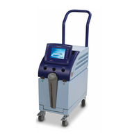
CritiCool
Belmont Medical Technologies CritiCool Manuals
Manuals and User Guides for Belmont Medical Technologies CritiCool. We have
6
Belmont Medical Technologies CritiCool manuals available for free PDF download: Service Manual, User Manual, Operational Training
Belmont Medical Technologies CritiCool Service Manual (133 pages)
Thermoregulation
Brand:
Belmont Medical Technologies
| Category:
Medical Equipment
| Size: 11 MB
Table of Contents
Table of Contents
3
Definitions
11
Applicable Systems
11
Essential Performance
11
End of Service Life Policy
11
Intended Use
12
Testing after Servicing the System
12
Warnings
12
Precautions
13
EMC Safety
14
Improper Use
14
Equipment Disposal and Recycling
14
Labels
15
Criticool Device Labels
15
Figure 1: Labels on Criticool Device
15
Symbols
16
Table 1: Symbols
16
Criticool System
18
External Features
19
Front View
19
Figure 2: Criticool Device: Front View
19
Side View
20
Rear Panel
20
Figure 3: Criticool Device: Side View
20
Figure 4: Criticool Device: Rear Panel
21
Accessories
22
Table 2: Accessories
22
Pre-Installation Requirements
23
Space and Environmental Requirements
23
Electrical Requirements
23
Inspection Prior to Unpacking
23
Unpacking the Criticool Device
24
Figure 5: Unpacking the Criticool Device
24
Assembling the Handle
25
Figure 6: Assembling the Handle
25
Accessory Kits
26
Table 3: 200-00300 Criticool Adult Accessory Kit with Reusable Probes
26
Table 4: 200-00310 Criticool Adult Accessory Kit for Use with Disposable Temperature Probes
26
Moving the Unit
27
Table 5: 200-00320 Criticool Infant Accessory Kit with Reusable Probes
27
Table 6: 200-00330 Criticool Infant Accessory Kit for Use with Disposable Temperature
27
Locking and Unlocking the Trolley Wheels
28
Storage Environment
28
Figure 7: Packing Instructions for Transport
28
Covers Assembly
29
Figure 8: Removing Criticool Covers
30
Removing the Covers and Handle
31
Removing the MMI (Man-Machine (User) Interface) Cover
31
Figure 9: MMI (Man-Machine (User) Interface) Cover
31
Figure 10: J4 on Controller Board
32
Removing the Left and Ride Side Covers
33
Figure 11: Removing the Left and Right Side Covers
33
Removing the Rear Cover
34
Removing the Bottom Front Cover
35
Removing the Top Cover
35
Figure 12: Removing the Bottom Front Cover
35
Removing the Handle
36
Figure 13: Removing the Handle
36
Removing the Trolley
37
Figure 14: Removing the Trolley
37
Table 7: Trolley Parts
37
Release of PCB Spacer Supports
39
Slide Lock Connector
39
Figure 15: Extraction Tool (from End)
39
Figure 16: Extraction Tool (from Side)
39
Power Supply Transformer Assembly
40
Removing the Power Supply Transformer Assembly
40
Figure 17: Slide Lock Connector
40
Power Supply Transformer Assembly Parts
41
Figure 18: Power Supply Transformer Assembly
41
Table 8: Power Supply Transformer Assembly Parts
41
Controller Board
42
Table 9: Controller Board - Power on Leds on the Controller
43
Controller Board Connectors
44
Controller Board Fuses
44
Table 10: Controller Board - Connectors
44
Controller Board Indicators
45
Figure 19: Controller Board Component Placement - Print Side
45
Controller Board Status
46
Figure 20: Controller Board Components
46
Table 11: Controller Board Status
46
Removing the Controller Board
47
Figure 21: Removing the Controller Board
47
Controller Board Parts
48
TEC (Thermo-Electric Components) Control Board
48
Table 12: Criticool Controller Board Parts
48
Table 13: TEC Control Board - Fuse List
48
Table 14: TEC Control Board - Connectors
49
Table 15: TEC Control Board LED Indicators
49
Removing TEC Control Board
50
Figure 22: TEC Control Board Components
50
TEC Controller Parts
51
Figure 23: TEC Controller Assembly
51
Table 16: TEC Controller Parts
51
Human Sensors (HS) Board
52
Figure 24: Human Sensors Board
52
Removing the Human Sensors Board
53
Table 17: Human Sensors Board - Input Signals
53
Table 18: Human Sensors Board - Connectors
53
Human Sensors Board Parts
54
Figure 25: Removing the Human Sensors Board
54
Table 19: Human Sensors Board Parts
54
Man-Machine (User) Interface (MMI)
55
Figure 26: Criticool Display
55
Table 20: MMI Criticool Display Part Number
55
FP Board
56
Figure 27: FP Board
56
Removing the FP Board
57
FP Board Parts
57
Figure 28: Removing the FP Board
57
Table 21: FP Board Parts
57
Heating Cooling Unit (HCU)
58
Figure 29: HCU Assembly
58
Table 22: HCU Assembly Part Number
58
Z Heat Exchanger
59
Thermal Exchange Components (Peltier)
59
Heat Sink
59
Figure 30: Z Heat Exchanger - Cross-Section
59
Fan
60
Removing the HCU
60
Figure 31: Removing the HCU
60
HCU Parts
61
Pump
61
Table 23: HCU Parts
61
Solenoid Bypass Valve
62
Removing the Solenoid Bypass Valve
62
Solenoid Bypass Valve Parts
62
Figure 32: Removing the Solenoid Bypass Valve
62
Table 24: Solenoid Bypass Valve Parts
62
Thermistors
63
Replacing the Water-Out and Thermostat Thermistor
63
Figure 33: Socket Location
63
Replacing the Water-In Thermistor
64
Float
64
Figure 34: Float Electrical Connections
64
Figure 35: Hydraulic System
66
Table 25: Hydraulic System - Block Diagram
66
Water Tank Assembly
67
Draining the Water Tank
67
Figure 36: Connecting Tubes and Special Male Connector
67
Removing the Water Tank
68
Water Tank Top Cover Assembly
68
Filter
68
Replacing the Filter
68
Figure 37: Filter
68
Removing the Filter
69
Installing the New Filter
69
Filter Parts
69
Figure 38: Filter Installation
69
Pump
70
Removing the Pump
70
Figure 39: Removing the Pump
70
Table 26: Filter Parts
70
Pump Parts
71
Table 27: Pump Parts
71
Pump Block Diagram
72
Pump Block Parts
72
Figure 40: Pump Block Diagram
72
Table 28: Pump Block Parts
72
Solenoid Bypass Valve
73
Water-In and Water-Out Connectors
73
Removing the Water-In and Water-Out Connectors
73
Figure 41: Removing the Water-In and Water-Out Connectors
73
Water Connector Parts
74
Table 29: Water Connector Parts
74
Self-Test on System Startup
75
Safety Algorithm
75
Halt Conditions
76
Table 30: HALT Conditions
76
Technician Mode Error Messages
78
Explanation of Error Messages
78
Table 31: Technician Mode Error Messages
78
Overview of the Periodic Maintenance Procedures
80
Technician Mode
81
Technician Mode Screens
81
Figure 42: Technician Mode Screen - Tab 1
81
Table 32: Technician Mode Screen - Tab 1 Components
82
Figure 43: Technician Mode Screen - Tab 2
83
Table 33: Technician Mode Screen - Tab 2 Components
83
Entering Technician Mode
84
Figure 44: Entering Technician Mode
84
Performing Periodic Maintenance Verification Tests
85
Completing the Periodic Maintenance Form
85
Removing the Covers
85
Water Filter and Air Intake Maintenance
86
Verifying Pump Life
86
Verifying Core and Surface (Human) Temperature Accuracy
86
Verifying Water Temperature Sensors
87
Table 34: Verification Form - Core and Surface Temperature Test Results
87
Table 35: Verification Form - Water Temperature Sensors
88
Verifying the Thermostat
89
Figure 45: Thermostat Socked on Human Sensors Board
89
Verifying the Pressure
90
Figure 46: Thermostat Verification Tool
90
Figure 47: FP Pressure Board
91
Table 36: Verification Form - Pressure
91
Verifying the Tecs Electrical Current
92
Figure 48: TEC Current Verification Unit
92
Verifying Fan Function
95
Performing a Self-Cleaning Procedure
96
Required Equipment
96
Performing the Self Cleaning Procedure
97
Checking for Water Leakage
98
Running the Self-Test
98
Leakage Current Test
98
Test System Organization
98
Figure 49: Leakage Test Equipment Connections
99
Figure 50: Grounding Locations on Device
100
Halt Messages
101
Table 37: Halt Messages - System Shutdown
101
Text Messages
103
Table 38: Text Messages
103
Calibration Tool Set: Verification and Calibration Units
105
Table 39: Calibration Toolset (Part Number 017-00210)
105
Temperature Calibration Unit (Part Number 017-00284)
106
Digital Pressure Gauge (Part Number 017-00290)
106
Figure 51: Temperature Simulator FOGG TP 400 (Part Number 017-00284)
106
Figure 52: Digital Pressure Gauge (Part Number 017-00290)
106
Installing the Digital Pressure Gauge
107
Figure 53: Water-Out Connection (Left) and Water-In Connection (Right)
107
Figure 54: Digital Pressure Gauge Connected
107
TEC Verification Unit (Part Number 017-00189)
108
Verification and Calibration Cables (Part Numbers 300-00093 and 300-00094)
108
Figure 55: TEC Verification Unit
108
Figure 56: Core Calibration Cable
108
Figure 57: Surface Calibration Cable
108
Thermostat Verification Tool (Part Number 017-00229)
109
PCB Extraction Tool (Part Number 017-00236)
109
Figure 58: Thermostat Verification Tool
109
Figure 59: PCB Extraction Tool
109
Standard Tools
110
Disclaimer
111
Criticool - Targeted Temperature Management
111
Figure 60: Criticool Control Unit
111
Criticool Spare Parts List
112
Table 40: Criticool Spare Parts List
112
Downloading Software to a PC
127
Downloading Software to the Criticool Device
127
Figure 61: Download Complete Message
128
Downloading the Color Display Panel Software
129
Figure 62: CRC Number
129
Figure 63: Color Display Panel Software Download
129
Figure 64: Display Loader Window
130
Instructions for Recycling
132
Table 41: Recycling Information
133
Advertisement
Belmont Medical Technologies CritiCool User Manual (125 pages)
Brand:
Belmont Medical Technologies
| Category:
Medical Equipment
| Size: 7 MB
Table of Contents
Table of Contents
5
Chapter 1: Safety Precautions
11
Definitions
11
Intended Use
11
Patient Target Group
11
Contraindications
11
Warnings
11
Precautions
12
EMC Safety
13
Improper Use
13
Labels
14
Figure 1: Label Placement for the Criticool Device
14
Label Symbols
15
Table 1: Key to Label Symbols
15
Chapter 2: System Description
17
General Description
17
Clinical Benefits
17
Criticool System
18
Criticool Device
18
External Features
19
Front View
19
Figure 2: Front View
19
Side View
20
Figure 3: Side View
20
Rear Panel
21
Figure 4: Rear View
21
Curewrap
22
Description and Intended Use
22
Wrap Material
22
Usage Duration
22
Risk of Reuse
22
Figure 5: Measurements
23
Selected Wrap Design
24
Accessories
24
Temperature Probes
24
Table 2: Curewrap
24
Figure 6: Disposable Core Temperature Probe Connection
26
Detachable Electric Power Cable & Plug
27
Connecting Tubes for Wrap
27
Figure 7: Disposable Surface Temperature Probe Connection
27
Table 3: Part Numbers: Disposable Temperature Probes and Associated Cables
27
Male Connector for Draining Water Tank
28
Spare Water Filter
28
Handle
28
Clinilogger (Optional)
28
Temperature Splitter (Optional)
29
System Specifications
29
Criticool Technical Specifications
30
Clinilogger ™ Technical Specifications
32
Chapter 3: Installation
33
Pre-Installation Requirements
33
Space and Environmental Requirements
33
Electrical Requirements
33
Equipment List
33
Unpacking and Inspection
34
Unpacking Criticool from the Box
34
Assembling the Handle
35
Moving the Unit
35
Preparation
35
Locking and Unlocking the Trolley Wheels
35
Figure 8: Handle Assembly
35
Packing Criticool for Shipment
36
Chapter 4: Operating Instructions
37
General
37
Criticool Functions
37
Controls, Functions, Indicators and Connections
38
Main Power Switch
38
Criticool ® Screen Controls
38
Table 4: Criticool Screen Keys
38
QCC- Quick Coupling Connectors
39
Temperature Probe Sockets
39
Patient Thermoregulation - Step by Step Operation
40
Operating the System
41
Figure 9: Self-Test Screen
41
Figure 10: Halt Error
42
Connecting the Water Hoses (Tubes) to Criticool
43
Inserting and Attaching Temperature Probes
44
Activating the System
45
Figure 11: Mode Select Upon Startup
45
Figure 12: Main Screen
45
Wrapping the Patient
46
The Control Panel
47
Figure 13: the Control Panel
47
Patient Mode
48
Figure 14: Settings Screen 1
49
Figure 15: Patient Mode Changed. Check Set Point
49
The Main Menu
52
Figure 16: Main Menu
52
Standby Mode
53
Figure 17: Standby Mode
53
Mode Select
54
Figure 18: Select Mode Panel
54
Temperature Graph
56
Figure 19: Temperature Graph
56
Figure 20: Temperature Graph
56
Settings
57
Figure 21: Settings Screen 1
57
Figure 22: Settings Screen 2
58
Figure 23: Settings Screen 3
58
Services
59
Figure 24: Settings Screen 4
59
Figure 25: Service Menu
59
Figure 26: Start Emptying Panel
60
Figure 27: Emptying Water - Performing Panel
61
Figure 28: Check Water Tubes
61
Modes of Operation
62
Figure 29: Select Mode Controlled Rewarming
66
Figure 30: Switching to Rewarming Message
66
Figure 31: Target Temperature Setting Panel
68
Figure 32: Holding Core Temp for First Step of Rewarming
69
Figure 33: Target Temperature Has Been Reached
70
Figure 34: Temperature Regulation Paused Message
71
Normothermia Management
73
Figure 35: Target Temperature Setting Panel
73
Figure 36: Normothermia Mode
74
Replacing the Wrap
75
Figure 37: out of Normothermia Range
75
Operation Panel Messages and Alerts
76
Figure 38: Adjustable Alarm Limits
76
TTM Mode Messages
77
Figure 39: Low Core Temperature Message
77
Figure 40: TTM Mode: Core Readout too Low Message
78
Figure 41: Thermoregulation Is Continuing Message
79
Controlled Rewarming Mode Messages
80
Figure 42: Controlled Rewarming Mode: Core Readout too Low Message
80
Figure 43: Thermoregulation Is Continuing Message
81
Chapter 5: Ordering Information
82
Equipment and Accessories
82
Available Wraps
82
Table 5: Wrap Information
82
Available Accessories
83
Table 6: Criticool Infant Reusable Accessory Kit (PN# 200-00320)
83
Table 7: Criticool Adult Reusable Accessory Kit (PN# 200-00300)
83
Table 8: Criticool Infant Disposable Accessory Kit (PN# 200-00330)
84
Table 9: Criticool Adult Disposable Accessory Kit (PN# 200-00310)
84
Table 10: Accessories
85
Chapter 6: Maintenance
86
Introduction
86
Service Information
86
Routine Maintenance
87
Table 11: Inspection and Maintenance Schedule
87
Routine Maintenance Overview
88
Before each Use
89
After each Use
89
Thermal Disinfection (Self-Cleaning)
90
System Check Service
91
Figure 44: Selecting System Check
91
Filter Replacement
92
Figure 45: System Check in Progress
92
Chapter 7: Troubleshooting
93
General
93
Troubleshooting Guide
93
Table 12: Criticool System Malfunction (no Message) Troubleshooting Guide
94
Table 13: Criticool Controlled Rewarming Mode Troubleshooting Guide
96
Figure 46: Male Draining Connector Attached to Connecting Water Hoses (for Emptying)
98
Table 14: Draining Criticool / Water Tank Overfilled
98
Table 15: Criticool System Technical Alarm Messages Troubleshooting Guide
99
Table 16: Criticool System Technical Alarm Messages Troubleshooting Guide
100
Table 17: Criticool System/Clinical Messages Troubleshooting Guide
101
Table 18: Criticool "Core Readout too Low" Safety Message Troubleshooting Guide
102
Table 19: Criticool System Messages (Notes) (V6.4 Only) Troubleshooting Guide
103
Table 20: Criticool Clinical Messages (Notes) Troubleshooting Guide
104
Table 21: Criticool Clinical Messages (Notes) Troubleshooting Guide
105
Chapter 8: Clinilogger Installation and Operating Instructions
106
Overview and Installation
106
Introduction
106
Using the Clinilogger Application
106
The Clinilogger ™ Software
106
Installing the Software
106
Figure 47: Clinilogger™ Initialization
107
Figure 48: Clinilogger Installation
107
Figure 49: Start Installation
108
Figure 50: Installation Progress
108
Figure 51: Installation Complete
109
Using the Clinilogger Viewer Application
110
Downloading Data
110
Figure 52: Clinilogger Application Window
110
Viewing Downloaded Data
111
Figure 53: Clinilogger Window
111
Figure 54: Choose Clinilogger
112
Figure 55: Complete Message
112
Clinilogger ™ Viewing Panel
113
Figure 56: Clinilogger™ Viewing Panel
113
Figure 57: Graphic Display Area
114
Figure 58: Example: Functional Status Area
115
Figure 59: Example: Modes and Errors Area
115
Table 22: Zoom Tool Buttons
117
Figure 60: Example of Modes and Error Area
119
Table 23: Clinilogger Mode Codes
119
Converting to Excel
120
Figure 61: Section of Excel Table
120
Ending a Viewing Session
121
Figure 62: Section of Graphic Chart
121
Appendix A
122
Belmont Medical Technologies CUSTOMER SERVICE REPRESENTATIVE
122
APPENDIX B: EMI / EMC Information
123
Table 24: Guidance and Manufacturer's Declaration - Emissions
123
Table 25: Guidance and Manufacturer's Declaration - Immunity
124
Appendix C: Waste Electrical & Electronic Equipment (Weee)
125
Belmont Medical Technologies CritiCool User Manual (121 pages)
Brand:
Belmont Medical Technologies
| Category:
Medical Equipment
| Size: 7 MB
Table of Contents
Table of Contents
5
Chapter 1: Safety Precautions
11
Definitions
11
Intended Use
11
Contraindications
11
Warnings
11
Precautions
12
EMC Safety
13
Improper Use
13
Labels
14
Figure 1: Label Placement for the Criticool Device
14
Label Symbols
15
Table 1: Key to Label Symbols
15
Chapter 2: System Description
17
General Description
17
Criticool System
18
Criticool Device
18
External Features
19
Front View
19
Figure 2: Front View
19
Side View
20
Figure 3: Side View
20
Rear Panel
21
Figure 4: Rear View
21
Curewrap
22
Description and Intended Use
22
Wrap Material
22
Usage Duration
22
Figure 5: Measurements
23
Selected Wrap Design
24
Accessories
24
Temperature Probes
24
Table 2: Curewrap
24
Figure 6: Disposable Temperature Probe Connections
26
Detachable Electric Power Cable & Plug
27
Connecting Tubes for Wrap
27
Male Connector for Draining Water Tank
27
Spare Water Filter
27
Handle
27
Clinilogger™ (Optional)
27
Table 3: Disposable Temperature Probes
27
Temperature Splitter (Optional)
28
System Specifications
28
Criticool ® Technical Specifications
29
Clinilogger™ Technical Specifications
31
Chapter 3: Installation
32
Pre-Installation Requirements
32
Space and Environmental Requirements
32
Electrical Requirements
32
Equipment List
32
Unpacking and Inspection
33
Unpacking Criticool from the Box
33
Assembling the Handle
34
Figure 7: Handle Assembly
34
Moving the Unit
35
Preparation
35
Locking and Unlocking the Trolley Wheels
35
Packing Criticool for Shipment
35
Chapter 4: Operating Instructions
36
General
36
Criticool Functions
37
Controls, Functions, Indicators and Connections
38
Main Power Switch
38
Criticool Screen Controls
38
Table 4: Criticool Screen Keys
38
QCC- Quick Coupling Connectors
39
Temperature Probe Sockets
40
Patient Thermoregulation - Step by Step Operation
40
Operating the System
40
Figure 8: Self-Test Screen
40
Inserting and Attaching Temperature Probes
42
Connecting the Water Hoses (Tubes) to Criticool
43
Activating the System
44
Figure 9: Mode Select Upon Startup
44
Figure 10: Main Screen
44
Wrapping the Patient
45
The Control Panel
45
Figure 11: the Control Panel
45
Patient Mode
46
The Main Menu
50
Figure 12: Main Menu
50
Standby Mode
51
Figure 13: Standby Mode
51
Mode Select
52
Figure 14: Select Mode Panel
52
Temperature Graph
54
Figure 15: Temperature Graph
54
Settings
55
Figure 16: Settings Screen 1
55
Figure 17: Settings Screen 2
56
Figure 18: Settings Screen 3
56
Figure 19: Settings Screen 4
57
Services
58
Figure 20: Start Emptying Panel
59
Figure 21: Emptying Water - Performing Panel
59
Modes of Operation
60
Figure 22: Core Readout too Low Message
61
Figure 23: Thermoregulation Is Continuing Message
62
Figure 24: Select Mode Controlled Rewarming
63
Figure 25: Switching to Rewarming Message
64
Figure 26: Controlled Rewarming Mode
64
Figure 27: Temperature Regulation Paused Message
65
Figure 28: Target Temperature Setting Panel
66
Normothermia Management
67
Figure 29: Normothermia Mode
68
Figure 30: out of Normothermia Message
69
Replacing the Wrap
70
Operation Panel Messages and Alerts
71
Figure 31: Adjustable Alarm Limits
71
Safety Messages and Alarms
72
Clinical Messages and Alarms
73
Table 5: Clinical Messages
73
Table 6: Clinical Messages
74
Technical Messages
75
Table 7: Technical Messages and Alarms
75
Table 8: Technical Messages and Alarms
76
Table 9: Technical Messages and Alarms
77
Informative Messages
78
TTM Mode Messages
79
Figure 32: Low Core Temperature Message
79
Figure 33: Temperature Regulation Paused Message
80
Figure 34: Thermoregulation Is Continuing Message
81
Controlled Rewarming Mode Messages
82
Figure 35: Core Readout too Low Message
82
Figure 36: Thermoregulation Is Continuing Message
83
Chapter 5: Ordering Information
84
Equipment and Accessories
84
Available Wraps
84
Table 10: Wrap Information
84
Available Accessories
85
Table 11: Criticool Infant Reusable Accessory Kit (PN# 200-00320)
85
Table 12: Criticool Adult Reusable Accessory Kit (PN# 200-00300)
85
Table 13: Criticool Infant Disposable Accessory Kit (PN# 200-00330)
86
Table 14: Criticool Adult Disposable Accessory Kit (PN# 200-00310)
86
Table 15: Accessories
86
Chapter 6: Maintenance
87
Introduction
87
Service Information
87
Routine Maintenance
88
Table 16: Inspection and Maintenance Schedule
88
Routine Maintenance Overview
89
Before each Use
89
Before Storage
90
Thermal Disinfection (Self-Cleaning)
91
System Check Service
91
Figure 37: Selecting System Check
92
Figure 38: System Check in Progress
92
Filter Replacement
93
Chapter 7: Troubleshooting
94
General
94
Troubleshooting Guide
94
Table 17: Criticool System Malfunction (no Message) Troubleshooting Guide
95
Table 18: Water Tank Overfilling
96
Table 19: Criticool® System Messages Troubleshooting Guide
97
Table 20: Criticool® System Messages Troubleshooting Guide
98
Table 21: Criticool® System Messages Troubleshooting Guide
99
Table 22: Criticool® System Messages Troubleshooting Guide
100
Table 23: Criticool® System Messages Troubleshooting Guide
101
Chapter 8: Clinilogger™ Installation and Operating Instructions
103
Overview and Installation
103
Introduction
103
Using the Clinilogger Application
103
The Clinilogger ™ Software
103
Installing the Software
103
Figure 39: Clinilogger™ Initialization
104
Figure 40: Clinilogger™ Installation
104
Figure 41: Start Installation
105
Figure 42: Installation Progress
105
Figure 43: Installation Complete
106
Using the Clinilogger Viewer Application
107
Downloading Data
107
Figure 44: Clinilogger™ Application Window
107
Viewing Downloaded Data
108
Figure 45: Clinilogger™ Window
108
Figure 46: Choose Clinilogger™ File Window
109
Figure 47: Complete Message
109
Clinilogger Viewing Panel
110
Figure 48: Clinilogger™ Viewing Panel
110
Figure 49: Graphic Display Area
111
Figure 50: Example: Functional Status Area
112
Figure 51: Example: Modes and Errors Area
112
Table 24: Zoom Tool Buttons
114
Figure 52: Example of Modes and Error Area
116
Table 25: Mode Codes
116
Converting to Excel
117
Figure 53: Section of Excel Table
117
Ending a Viewing Session
118
Figure 54: Section of Graphic Chart
118
Belmont Medical Technologies CUSTOMER SERVICE REPRESENTATIVE
119
Appendix B: Rf Separation
120
Table 26: Separation Distances in Meters
120
Appendix C: Waste Electrical & Electronic Equipment (Weee)
121
Advertisement
Belmont Medical Technologies CritiCool User Manual (115 pages)
Brand:
Belmont Medical Technologies
| Category:
Medical Equipment
| Size: 6 MB
Table of Contents
Operator Profile
3
Training
3
Use of Manual
3
Disclaimer
4
Important Notice
4
Table of Contents
5
Chapter 1: Safety Precautions Definitions
11
Intended Use
11
Warnings
11
Precautions
12
EMC Safety
13
Improper Use
13
Labels
14
Criticool ® Device Labels
14
Figure 1-1: Label Placement for the Criticool ® Device
14
Label Symbols
15
Table 1-1: Key to Label Symbols
15
System Description
16
General Description
16
Criticool ® System
17
Criticool ® Device
17
External Features
18
Front View
18
Figure 2-1: Front View
18
Side View
19
Figure 2-2: Side View
19
Rear Panel
20
Wrap
20
Figure 2-3: Rear View
20
Figure 2-4: Measurements
22
Accessories
23
Table 2-1: Curewrap
23
Figure 2-5: Disposable Temperature Probe Connections
25
System Specifications
26
Table 2-2: Disposable Temperature Probes
26
Table 2-3: Probe and Data Provider Input Specifications
26
Chapter 3: Installation
28
Pre-Installation Requirements
28
Space and Environmental Requirements
28
Electrical Requirements
28
Unpacking and Inspection
28
Assembling the Handle
29
Equipment List
29
Figure 3-1: Handle Assembly
29
Moving the Unit
30
Preparation
30
Locking and Unlocking the Trolley Wheels
30
Operating Instructions
31
General
31
Application Specification
31
Indication for Use
31
Location
31
Patient Age and Weight
31
Getting Started
32
Turning on the System
32
Main Power Switch
32
Figure 4-1: Self-Test Screen
33
Figure 4-2: Mode Select Upon Startup
33
Inserting and Attaching Temperature Probes
34
Temperature Probes
34
Figure 4-3: Main Screen
34
Wrapping the Patient
35
Connecting the Tubes
35
Criticool ® Screen Control Keys
37
Table 4-1: Criticool ® Control Keys
37
The Control Panel
38
Figure 4-4: the Control Panel
38
Patient Mode
39
Neonatal Mode
41
Adult Mode
41
The Main Menu
43
Figure 4-5: Main Menu
43
Standby Mode
44
Figure 4-6: Standby Mode
44
Mode Select
45
Figure 4-7: Select Mode Panel
45
TTM (Targeted Temperature Management)
46
Controlled Rewarming
46
Normothermia
46
Shutting down the Device
47
Main Power Switch
47
Temperature Graph
47
Figure 4-8: Temperature Graph
47
Settings
48
Services
51
Empty
51
Modes of Operation
52
Targeted Temperature Management (TTM) Mode
52
Figure 4-13: Start Emptying Panel
52
Figure 4-14: Emptying Water - Performing Panel
52
Figure 4-15: Core Readout too Low Message
54
Controlled Rewarming Mode
55
Controlled Rewarming Process
55
Figure 4-16: Thermoregulation Is Continuing Message
55
Figure 4-17: Select Mode Controlled Rewarming
57
Figure 4-18: Switching to Rewarming Message
57
Figure 4-19: Controlled Rewarming Mode
58
Figure 4-20: Temperature Regulation Paused Message
58
Target Temperature Setting
59
Figure 4-21: Target Temperature Setting Panel
59
Manual Rewarming
60
Normothermia Management
60
Normothermia
60
Figure 4-22: Normothermia Mode
61
Exceeding the Normothermia Range
62
Figure 4-23: out of Normothermia Message
62
Replacing the Wrap
63
Operation Panel Messages
64
Technical Messages
64
Table 4-2: Technical Messages and Alarms
64
Clinical Messages
67
Table 4-3: Clinical Messages
67
Safety Messages and Alarms
69
Informative Messages
70
Constant Alarms
71
Figure 4-24: Adjustable Alarm Limits
71
TTM Mode Messages
72
Figure 4-25: Low Core Temperature Message
72
Figure 4-26: Temperature Regulation Paused Message
73
Figure 4-27: Thermoregulation Is Continuing Message
73
Controlled Rewarming Mode Messages
74
Figure 4-28: Core Readout too Low Message
74
Figure 4-29: Thermoregulation Is Continuing Message
75
Chapter 5: Ordering Information
76
Equipment and Accessories
76
Available Wraps
76
Table 5-1: Wrap Information
76
Table 5-2: Kit Sub Part Number
77
Table 5-3: Accessory Part Numbers
79
Chapter 6: Maintenance
80
Introduction
80
Service Information
80
Routine Maintenance
80
Cleaning and Disinfection
81
Routine Maintenance of External Surfaces
81
Table 6-1: Inspection and Maintenance Schedule
81
Required Tools for Cleaning and Disinfection
82
Recommended Disinfectants for External Surfaces
82
Before each Use
82
Before Storage
83
Thermal Disinfection
84
Cautions
84
Thermal Disinfection Process
85
Figure 6-1: Selecting Thermal Disinfection Service
85
Figure 6-2: Thermal Disinfection Mode
86
Figure 6-3: Thermal Disinfection Mode in Progress
86
Cleaning, Disinfecting and Sterilization of the Reusable Temperature Probes
87
System Check Service
87
Figure 6-4: Selecting System Check
88
Figure 6-5: System Check in Progress
88
Filter Replacement
89
Chapter 7: Troubleshooting
90
General
90
Troubleshooting Guide
90
Figure 7-1: Curewrap ™ Connecting Tubes and Special Male Connector
92
Table 7-2: Water Tank Overfilling
92
Table 7-3: Criticool ® System Messages Troubleshooting Guide
93
Overview and Installation
98
Introduction
98
Using the Clinilogger ™ Application
98
The Clinilogger ™ Software
98
Installing the Software
98
Figure 8-1: Clinilogger ™ Initialization
99
Figure 8-2: Clinilogger ™ Installation
99
Figure 8-3: Start Installation
100
Figure 8-4: Installation Progress
100
Figure 8-5: Installation Complete
101
Using the Clinilogger ™ Viewer Application
102
Downloading Data
102
Figure 8-6: Clinilogger ™ Application Window
102
Viewing Downloaded Data
103
Figure 8-7: Clinilogger ™ Window
103
Figure 8-8: Choose Clinilogger ™ File Window
104
Figure 8-9: Complete Message
104
Clinilogger ™ Viewing Panel
105
Figure 8-10: Clinilogger ™ Viewing Panel
105
Graphic Display Area
106
Figure 8-11: Graphic Display Area
106
Function Selection Area
107
Temperature Graph Control Buttons
107
Figure 8-12: Example: Functional Status Area
107
Figure 8-13: Example: Modes and Errors Area
107
Display/Hide Buttons
108
Color Buttons
108
View Manipulation Buttons
108
Table 8-1: Zoom Tool Buttons
108
Cursor Line
109
Modes and Error Area
110
Figure 8-14: Example of Modes and Error Area
110
Table 8-2: Mode Codes
110
Functional Status Area-Heat/Cool and Pump On/Power off
111
Converting to Excel
112
Figure 8-15: Section of Excel Table
112
Figure 8-16: Section of Graphic Chart
112
Ending a Viewing Session
113
Belmont Medical Technologies Customer Service Representative
114
Appendix B: RF Separation
115
Table B-1: Separation Distances in Meters
115
Belmont Medical Technologies CritiCool Operational Training (79 pages)
Brand:
Belmont Medical Technologies
| Category:
Medical Equipment
| Size: 13 MB
Table of Contents
Main Operation Screen
33
Menu Options
35
Temperature Graph
36
Standby Mode
40
Select Mode
41
Maintenance
51
Routine Maintenance
52
Service Screen
55
Messages and Troubleshooting
58
Alarm Message
60
Water Temperature Settings
68
Important Points
77
Belmont Medical Technologies CritiCool Operational Training (74 pages)
Brand:
Belmont Medical Technologies
| Category:
Medical Equipment
| Size: 7 MB
Table of Contents
Menu Options
34
Temperature Graph
36
Standby Mode
40
Select Mode
41
Maintenance
46
Service Screen
47
Thermal Disinfection
49
Routine Maintenance
50
Messages and Troubleshooting
52
Alarm Message
54
Water Temperature Settings
62
Important Points
72
Advertisement
Related Products
Belmont Medical Technologies CRITICOOL MINI
Belmont Medical Technologies HYPERTHERMIA PUMP
Belmont Medical Technologies Hyperthermia Pump 505
Belmont Medical Technologies RAPID INFUSER RI-2
Belmont Medical Technologies Categories
Medical Equipment
Food Warmer
More Belmont Medical Technologies Manuals
Login
Sign In
OR
Sign in with Facebook
Sign in with Google
Upload manual
Upload from disk
Upload from URL