Table of Contents
Advertisement
Quick Links
Advertisement
Table of Contents

Subscribe to Our Youtube Channel
Related Manuals for Summa L1810 2nd generation


Summary of Contents for Summa L1810 2nd generation
- Page 1 L1810 2 generation LASER CUTTER User Manual Rev 002...
- Page 2 Failure to register the L1810 Gen2 laser cutter may result in a delayed response to warranty and service inquiries. Contact Information All inquiries, comments or suggestions concerning this and other Summa manuals should be directed to: Summa, nv Rochesterlaan 6...
- Page 3 Even most intricate details are a breeze to cut with Summa laser cutting technology. Discover the many other advantages Summa laser cutting technology has to offer in this manual.
- Page 4 L1810 2 generation User’s Manual Revision history Version Reason for modification Publication date Author Original version 31 March 2022 A.L. • Updated danger zone 13 January 2023 A.L. • Updated laser cutter overview • Deleted chapter unwinder: available as separate manual •...
-
Page 5: Table Of Contents
L1810 2 generation User’s Manual Table of Contents Safety ........................ 8 Safety ........................ 8 General ........................8 1.1.1 Symbols used in this manual ..................8 1.1.2 Safety symbols on the machine ................9 1.1.3 Safety precautions ....................10 1.1.4 Danger area during operation ................10 Safety precautions related to movement ............. - Page 6 L1810 2 generation User’s Manual Unwinder (optional) ..................27 Fume extraction and vacuum system ............28 Air filtration units (optional)................... 28 2.3.1 Extraction fan (optional) ..................28 2.3.2 Water chiller (optional) ................... 29 General Description ..................... 29 2.4.1 Temperature ......................29 2.4.2 Safety precautions ....................
- Page 7 L1810 2 generation User’s Manual Maintenance Overview ................... 78 Consumables and reprocessable items ............80 Consumables ....................80 Reprocessable items ..................80 Troubleshooting ..................... 81 Error Messages ....................82 GoCare ......................84 GoProduce Laser Edition ................85...
-
Page 8: Safety
L1810 2 generation User’s Manual SAFETY Safety 1.1.1 General The manufacturer has no direct control over the machine operation and application. Proper safety practice is the sole responsibility of the owner, user, and operator. All instructions and safety warnings in this manual are based upon the use of this machine under proper operating conditions without alterations from the original design. -
Page 9: Safety Symbols On The Machine
L1810 2 generation User’s Manual 1.1.3 Safety symbols on the machine Safety labels are used on some parts of the machine. They are explained below. Caution Servicing instructions are for use by qualified service personnel only. To reduce the risk of electric shock, do not open the equipment and do not perform any servicing other than that contained in the operating instructions unless you are qualified to do so. -
Page 10: Safety Precautions
L1810 2 generation User’s Manual 1.1.4 Safety precautions WARNING: This equipment is not suitable for use in locations where children are likely to be present. Danger area during operation The general danger area is the yellow area: the complete area where the conveyor is moving, and the fabric roll is in motion. -
Page 11: Safety Precautions Related To The System Components
L1810 2 generation User’s Manual Safety precautions related to the system components When closing the safety cover, ensure that no fingers or other items can be trapped between the safety cover and the side pod. When the safety cover is lifted, care must be taken to avoid bumping your head against it. -
Page 12: Safety Cover Lid And Finger Safety Plates
L1810 2 generation User’s Manual Safety cover lid and finger safety plates When the safety cover lid of the cutting area is opened or the finger safety plates are triggered, the laser stops firing, and the cutting job is paused. A warning on the touch control panel pops up, prompting the operator to close the cover. -
Page 13: Laser Cutting System Components
L1810 2 generation User’s Manual LASER CUTTING SYSTEM COMPONENTS Laser cutter Unwinder Two air filtration units or one extraction fan Water chiller (if applicable) Laser cutting system components... -
Page 14: Laser Cutter
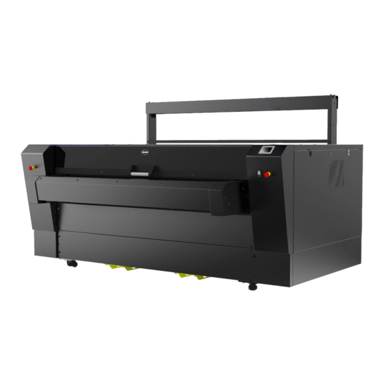
L1810 2 generation User’s Manual Laser Cutter L1810 Gen2 with front extension table and Vision camera system - front view Laser cutting system components... - Page 15 L1810 2 generation User’s Manual L1810 Gen2 with front extension table and Vision camera system - rear view (1) Main power switch (8) Conveyor system (blade or honeycomb planks) (2) ON/OFF buttons (9) Fume extraction/vacuum chamber (3) Emergency stop buttons (10) Cutting head nozzle (4) Ethernet connection (11) Head camera...
-
Page 16: Main Power Switch
2.1.4 Ethernet connection If your laser cutter is equipped with the Vision camera system, Summa provides a computer in the right cabinet of the cutter, connected to the Ethernet connection on the rear of the cutter. If your laser cutter is not equipped with the Vision camera system, the computer (provided by the end-user) is connected with the cutter by means of a USB cable, running from the main board inside the cabinet along the underside of the machine to the external computer. -
Page 17: Touch Control Panel
L1810 2 generation User’s Manual 2.1.5 Touch control panel The touch control panel is a unique interface system providing detailed cutter information and offering a flexible and powerful control of the cutter’s configuration. If applicable, tips or advice will be shown here. After a certain period of inactivity of the panel, the screensaver appears. -
Page 18: Settings Screen
L1810 2 generation User’s Manual Settings screen Home Home 100 % 10 cm/s Maximum power Feed velocity 10 % High Minimum power Quality level More More Velocity 800 mm/s General 1000 mm/s Up velocity Calibrate touch screen Down acceleration Laser enable 0.8 g True 3000 mm... -
Page 19: Parameters
L1810 2 generation User’s Manual 2.1.5.2.1 Parameters Maximum Power Minimum Power: For the calibration functions of the laser. Please • note that GoProduce Laser Edition overrides these settings when a job is sent: the maximum power and minimum power settings on the control panel only affect the calibration power of the laser. -
Page 20: Actions Screen
L1810 2 generation User’s Manual Actions Screen Home Reset Recut Feed Spot mode DIN A4 test Actions 2.1.5.3.1 Parameters • Reset: for clearing the last job sent from GoProduce Laser Edition to the laser. • Recut: for resending the last job sent from GoProduce Laser Edition to the laser. •... -
Page 21: Set Origin Screen
L1810 2 generation User’s Manual Set Origin Screen Cancel Set origin Reset X: 0 Y: 0 Apply Access this screen by clicking in the home screen. The X and Y coordinates are displayed in the centre of the screen so that you can choose an exact origin if required, for example if you require using a jig. -
Page 22: Media Size Screen
L1810 2 generation User’s Manual Media Size Screen Cancel Media size Reset X: 0 Y: 0 Apply After having set the origin, this screen appears. The X and Y coordinates are displayed in the centre of the screen so that you can choose an exact media size if required, for example if you require using a jig. -
Page 23: Pause Screen
L1810 2 generation User’s Manual Pause Screen Pause Resume When paused and if you wish to check the cut quality, tap the arrows to move the cutting head away from the cut material. Resume to move the cutting head back to its previous position and resume cutting. Information Screen L1810 Gen2 Serial number: L32110-10001... -
Page 24: Conveyor System
L1810 2 generation User’s Manual 2.1.8 Conveyor system The conveyor system, equipped with honeycomb or blade conveyor planks, transports the material through the working area and then out of the machine. The material is held down by the vacuum/extraction system underneath the conveyor bed, resulting in a clean cut and precise material transport. -
Page 25: Cutting Head Nozzle
L1810 2 generation User’s Manual 2.1.10 Cutting head nozzle The cutting head nozzle emits the laser beam that cuts the material in the cutting area. Nozzle height To have a clean cut a good focus of the laser beam is required. As a rule of thumb, we set the nozzle 4mm above the material. -
Page 26: Head Camera
L1810 2 generation User’s Manual 2.1.11 Head camera The laser cutter is always equipped with a head camera. The head camera supports the following advanced work methods: • Cut-to-Frame (also known as Fixed Size cutting) • Barcode workflow (requires Pro Pack). •... -
Page 27: Unwinder (Optional)
As the roll unwinds, a loop is created to relax the material, reducing distortion, and secure an accurate cut. The user manual of the unwinders is available for download on our website (www.summa.com/en/support/user-manuals/). Laser cutting system components... -
Page 28: Fume Extraction And Vacuum System
L1810 2 generation User’s Manual Fume extraction and vacuum system WARNING: Before commencing any cutting procedure, ensure that the fume extraction system is in good working order and operates correctly. Some material may produce hazardous fumes if cut using the laser – check with the material supplier or manufacturer before cutting. -
Page 29: Water Chiller (Optional)
Water chiller (optional) NOTE: The information in this chapter only applies to the water chiller supplied by Summa. If another water chiller is used, this information is not applicable, and you should refer to the supplier's documentation of your water chiller. -
Page 30: Safety Precautions
L1810 2 generation User’s Manual ATTENTION: Under no circumstances should the water temperature be allowed to reach or fall below dew point. ATTENTION: Operating the cooler unit at temperatures lower than those specified may result in serious damage to the laser due to condensation. This type of damage is not covered by manufacturer warranty. -
Page 31: Starting Up The Laser Cutter
Switch on the power supply to the laser cutter. Power on the laser cutter. The control panel displays the Summa splash screen for several seconds. The loading screen is displayed, and the motion system moves to its home position. If one of the covers is open, however, the motion system does not move and the “Close cover!”... -
Page 32: Maintenance
L1810 2 generation User’s Manual MAINTENANCE This chapter explains all maintenance works that need to be performed on the laser cutting system. A complete overview can be found in chapter 4.5 Maintenance Overview on page 78. WARNING: Before performing any maintenance, disconnect the laser cutter from the main power supply. -
Page 33: Laser Beam Alignment
It is ALWAYS, also including during this calibration process, prohibited to adapt, disable or override the safety systems of the machine. When the machine is misused or when the safety systems are not functioning as defined by the manufacturer, Summa cannot be held accountable for any mechanical damage or injuries caused. -
Page 34: Preparation
L1810 2 generation User’s Manual Preparation Covers Open the polycarbonate lid. Remove the four screws on the bottom of the front hinge cover and open the cover. Use the universal cross key to unlock (do not remove) the left panel. Maintenance... -
Page 35: Spot Mode
L1810 2 generation User’s Manual 4.1.1.2.1 Spot mode Spot mode allows you to fire the laser manually for a set amount of time with a set percentage of power. It will be frequently used throughout the calibration process. In the home screen, press Actions >... - Page 36 L1810 2 generation User’s Manual Navigate back to the Spot mode screen, use the arrow keys to position the cutting head. Press Fire > to fire the laser (in some cases multiple shots will be required to obtain a clear mark on the target). Use spot mode after every adjustment.
-
Page 37: Laser Alignment
L1810 2 generation User’s Manual Laser alignment The purpose of this adjustment is to get the laser beam to hit the material properly at any position. Poorly aligned lasers can cause a less powerful output at the nozzle, damage, or harm to the operator due to unpredictable reflections. -
Page 38: Check Corners
L1810 2 generation User’s Manual 4.1.1.3.2 Check corners Start by checking if the laser hits the target in the centre in all four corners of the working area. Put the target holder with a target in the cutting head opening. Use spot mode to fire the laser in the order pictured below. - Page 39 The actual results can vary due to mechanical tolerances. CASE 1: There are no marks on the targets. Contact your Summa dealer for further technical support. CASE 2: There is only a mark on target 1. Continue to chapter 4.1.1.3.3.1 Check beam path on page 43.
- Page 40 CASE 4: The marks on targets 1, 2, and 3 are in the same place but not centred. This means that the laser module or primary mirror slide probably moved. Contact your Summa dealer for further technical support. CASE 5: The marks on targets 1 and 2 are in the same place, while the marks on targets 3 and 4 are lower or higher than that.
- Page 41 L1810 2 generation User’s Manual CASE 6: The marks on targets 1 and 2 are centred, but the marks on targets 3 and 4 do not meet the specifications. Follow the procedure from chapter 4.1.1.3.4.2 Laser parallel with top beam axis on page 50 and use the specifications below. Target No Position Result...
-
Page 42: Primary Mirror Calibration
L1810 2 generation User’s Manual 4.1.1.3.3 Primary mirror calibration The primary mirror is the first component that reflects the laser beam. It is in front of the laser unit. The primary mirror changes the angle (not the height!) of the laser beam. The angle can be adjusted by means of the thumbscrews on the mirror holder (... - Page 43 L1810 2 generation User’s Manual 4.1.1.3.3.1 Check beam path This calibration ensures that the laser hits the secondary mirror on the far left and right of the machine. (Re)place a target in the cutting head. Use spot mode to move the head all the way to the front left side and fire the laser. Move the cutting head about 25cm to the right.
- Page 44 L1810 2 generation User’s Manual Unscrew the locknuts and adjust the thumbscrews on the primary mirror to shoot as close as possible to the first mark. : Up and down : Left and right Close the left side cover and return to step 1. Maintenance...
- Page 45 L1810 2 generation User’s Manual 4.1.1.3.3.2 Laser beam parallel with front axis The purpose of this calibration is to align the laser parallel to the front axis. This ensures that the laser beam always hits the secondary mirror at the same spot, regardless of where it is positioned along the front axis.
- Page 46 L1810 2 generation User’s Manual Open the left side cover. Unscrew the locknuts and adjust the thumbscrews on the primary mirror to shoot as close as possible to the first mark. : Up and down : Left and right Close the left side cover and return to step 1.
-
Page 47: Secondary Mirror
L1810 2 generation User’s Manual 4.1.1.3.4 Secondary mirror The secondary mirror is mounted on the top beam. It moves along with the top beam and reflects the laser beam to the cutting head. Adjusting the mirror holder can be done by means of the thumbscrews ( and ). The locknut ... - Page 48 L1810 2 generation User’s Manual 4.1.1.3.4.1 Check beam path This calibration ensures that the laser hits the (45º angled) third mirror in the cutting head when it is positioned in the front and back of the top beam. Put the target holder with a target in the cutting head opening. Use spot mode to fire the laser when the head is at its origin position.
- Page 49 L1810 2 generation User’s Manual Unscrew the locknuts and adjust the secondary mirror to shoot as close as possible to first mark. : Up and down : Left and right Return to step 4. Maintenance...
- Page 50 L1810 2 generation User’s Manual 4.1.1.3.4.2 Laser parallel with top beam axis Like the previous calibration, this will align the laser parallel to the top beam axis. This ensures that the laser beam always hits the (45º angled) third mirror at the same spot, regardless of where it is positioned along the top beam axis.
- Page 51 L1810 2 generation User’s Manual Move the head all the way to the back and fire the laser. Marks are on top of each other Marks NOT on top of each other Continue to chapter 4.1.1.3.5 Third (45º Continue to step 4. angled) mirror on page 52.
-
Page 52: Third (45º Angled) Mirror
L1810 2 generation User’s Manual 4.1.1.3.5 Third (45º angled) mirror This is the last mirror in the beam path and guides the laser beam through the centre opening of the nozzle. Maintenance... - Page 53 L1810 2 generation User’s Manual 4.1.1.3.5.1 Centring laser beam through nozzle Use the thumbscrew to raise the nozzle as high as possible. Mount the nozzle target holder on the bottom of the nozzle. (Re)place the target. Maintenance...
- Page 54 L1810 2 generation User’s Manual Use spot mode to fire the laser. Mark perfectly centred on target Mark NOT centred on target Continue to chapter 4.1.1.3.6 Final corners Continue to step 5. check on page 55. Use the hex screws to centre the mark on the target. ...
-
Page 55: Final Corners Check
L1810 2 generation User’s Manual 4.1.1.3.6 Final corners check After the above calibrations have been performed, the laser beam should hit the target as specified below. Put the target holder with a target in the cutting head opening. Use spot mode to fire the laser in the order pictured below. Maintenance... - Page 56 L1810 2 generation User’s Manual The results should match the specifications below. Target No Position Result Front left Mark centred on target Front right Mark centred on target Back right Mark centred on target Back left Mark centred on target Marks within specification Marks NOT within specification Remove the nozzle target holder.
-
Page 57: Optical Components
L1810 2 generation User’s Manual 4.1.2 Optical components To achieve maximal power output from the laser cutter, the system’s optical components must be in good working order. Poorly cleaned optics absorb more heat and are more likely to burn or shatter! Laser unit ... -
Page 58: Cleaning The Primary Mirror
L1810 2 generation User’s Manual Cleaning the primary mirror Remove the left-hand side cover of the laser cutter using a control cabinet key to gain access to the primary mirror. Apply a small amount of IPA optical cleaning solution onto the cleaning cloth provided in the tool kit and clean the mirror while in position. -
Page 59: Cleaning The Secondary Mirror
L1810 2 generation User’s Manual Cleaning the secondary mirror 1. Open the safety cover lid. 2. Remove the four bottom screws of the front guard and open it. 3. Apply a small amount of IPA optical cleaning solution onto the cleaning cloth provided in the tool kit and clean the mirror while in position. -
Page 60: (Un)Installing The Static And Travelling Mirrors
L1810 2 generation User’s Manual (Un)Installing the static and travelling mirrors For removing the static and travelling mirrors from their mount (e.g., in the event of a defect) and installing them again, use the spanner wrench (delivered in the toolbox). 4.1.2.3.1 Removing the mirror Place the spanner wrench on the mirror retaining washer so that the notches fit together. -
Page 61: Cleaning The Cutting Head Lens
L1810 2 generation User’s Manual Cleaning the cutting head lens The cutting head lens coating is fragile; do not drop the lens onto any hard surface or touch the lens with any sharp objects as this may damage the lens and reduce cutting efficiency. Always use cloths that are moistened with IPA optical cleaning solution;... - Page 62 L1810 2 generation User’s Manual Remove the lens ring by turning it counterclockwise. Carefully drop the lens onto a clean microfibre cloth. WARNING: Ensure that the area is sufficiently ventilated. The solvent should be kept away from heat or flames. Wear appropriate clothing and safety goggles. Do not breathe in the fumes.
- Page 63 L1810 2 generation User’s Manual This is a good time to also clean the nozzle. For more information, refer to chapter 4.1.3.1 Nozzle cleaning on page 66. Hold the edges of the lens with the convex surface facing upward and carefully place it into the nozzle barrel.
-
Page 64: Cleaning The Cutting Head Mirror
L1810 2 generation User’s Manual Cleaning the cutting head mirror Remove the cutting head by releasing the M4 screw and detaching the pneumatic tube. Release (do not remove) the mirror securing screw holding the mirror securing clip. Rotate the clip to release the mirror. Maintenance... - Page 65 L1810 2 generation User’s Manual Gently rotate the head so that the mirror falls out onto a microfibre cleaning cloth. Apply IPA optical cleaning solution to the mirror face and let it soak for a few seconds. Gently lay an optical cleaning solution cloth on one edge of the mirror and gently draw the cloth right across the mirror in one continuous movement.
-
Page 66: Pneumatics
L1810 2 generation User’s Manual 4.1.3 Pneumatics Nozzle cleaning To ensure proper airflow while cutting, the nozzle needs to be free of dirt. This step is preferably done with the barrel disassembled and the lens removed. Remove the cutting head by releasing the M4 screw and detaching the pneumatic tube. Clean the hole using a wooden toothpick. -
Page 67: Airflow
L1810 2 generation User’s Manual Airflow Depending on the type of material being processed, an appropriate airflow must be present. Find the pressure regulator at the back of the machine. Check if all pneumatics tubes are still connected properly. Check the pressure gauge to see if it is set properly: range between 0.5 bar (7.2psi) and 3 bar (43.51psi). -
Page 68: Axes
L1810 2 generation User’s Manual 4.1.4 Axes Axis movement Check smooth movement on both axes. Use the arrow keys at the Set Origin screen to move the cutting head to each corner of the cutting bed and check for any irregularities. For more information, refer to Set Origin Screen on page 21. -
Page 69: Air Filters
L1810 2 generation User’s Manual 4.1.5 Air filters To protect the internal components from surrounding dust particles, three filters are fitted around the machine. Open the left and the right cover using the control cabinet key. Remove the filter from the left/right cover and the back panel. Vacuum all the filters. -
Page 70: Conveyor Planks
L1810 2 generation User’s Manual 4.1.6 Conveyor planks To ensure proper fume extraction and vacuum for material transportation, the conveyor planks need to be free of dust and lint. Open the safety cover lid and visually inspect the conveyor planks for cleanness and damage. -
Page 71: Air-Cooled Laser
L1810 2 generation User’s Manual Air-cooled laser This section is only applicable if an air-cooled laser unit is installed inside the laser cutter. Check the serial number label on the back right of the machine. An air-cooled laser cutting machine type ends with /50 or /100. 4.2.1 Laser unit Attention should be paid to proper airflow through the laser. -
Page 72: Water-Cooled Laser
L1810 2 generation User’s Manual Water-cooled laser This section is only applicable if a water-cooled laser unit is installed inside the laser cutter. Check the serial number label on the back right of the machine. A water-cooled laser cutting machine type ends with /120 or /250. 4.3.1 Water-cooled laser unit The water-cooled laser unit has been designed to be low maintenance. -
Page 73: Chiller
L1810 2 generation User’s Manual 4.3.2 Chiller The laser unit is cooled with deionised water, to avoid bacterial infestation. Water level The chiller needs a controlled water level to deliver full cooling capacity. 1. Check the water level through the inspection glass. The water level should be at least halfway. -
Page 74: Water Quality
L1810 2 generation User’s Manual Water quality Over time, the chiller water can become cloudy. Cloudy chiller water is no longer good for use. Replace with deionised water only. Remove the reservoir cap. Open the valve at the bottom of the chiller to drain all the chiller water. Unplug the blue tube. -
Page 75: Water Pipes
L1810 2 generation User’s Manual Water pipes To ensure proper water flow, the water hoses need to be in good condition and without kinks or sharp bends. Close the IN and OUT valves on the chiller. Drain the water from the damaged water hose. Replace the water hose with a new one of the same length. -
Page 76: Chiller Air Filter
L1810 2 generation User’s Manual Refit the water hose into the chiller and open both valves completely. Chiller air filter To ensure proper airflow through the chiller, the grid and the air filter need to be free of dust. The filter can be easily removed by hand. Lift the filter and tilt outwards to slide it out. -
Page 77: Extraction Systems
L1810 2 generation User’s Manual Extraction systems To ensure proper fume extraction and vacuum in the cutting area, the extraction hoses need free of dust and debris. Remove the vacuum hose from the extraction system (extraction fan, BOFA, or own system). Illustration purely indicative Visually inspect the inside of the fan and extraction hose. -
Page 78: Maintenance Overview
L1810 2 generation User’s Manual Maintenance Overview ATTENTION: Make sure the power supply to the laser cutter is switched off before starting maintenance tasks! ATTENTION: The intervals below are the maximum allowed time between maintenance tasks: • 8 hours or one day* •... - Page 79 L1810 2 generation User’s Manual LASER CUTTER Component Task Max. Interval* Reference Vision camera lens Clean/Check and scanning camera Dealer 1 Year calibration UV filter Clean and All Rails Dealer 1 Year Lubricate X-Belt Tension Check/Adjust Dealer 1 Year Y-Belts Tension Check/Adjust Dealer 1 Year...
-
Page 80: Consumables And Reprocessable Items
L1810 2 generation User’s Manual CONSUMABLES AND REPROCESSABLE ITEMS Consumables Part Number Description 600-6028 Standard 2,5’ FL Lens 600-6029 Standard FB Mirror 600-6034 Optical Cleaning Fluid 600-6035 Optics Cleaning Cloth 600-6053 Alignment Targets 600-6055 Laser Safety Glasses 600-6133 Alignment Kit 610-8560 Assy Nozzle Barrel MK2 600-6132... -
Page 81: Troubleshooting
L1810 2 generation User’s Manual TROUBLESHOOTING The laser is not cutting well in all areas of the bed: • The focus height is incorrect. • The lens is upside down. • The optical components are in a poor state of cleanliness. •... -
Page 82: Error Messages
L1810 2 generation User’s Manual Error Messages Error Possible Checks Corrective Action Message Cause Material Check affected area for any Object loose material, objects or thread Remove any debris from obstructing that have become moving parts movement entangled in moving parts Rail Dirty Check the rail for any ingrained Remove dirt with green... - Page 83 L1810 2 generation User’s Manual Error Possible Cause Checks Corrective Action Message End-of-roll sensor Check if material loop covers Unwind material until unwinder the sensor sensor is covered De-reeler uncovered Material Interlock switch Check all interlock switches Replace repair damaged, and plugs necessary, contact...
-
Page 84: Gocare
L1810 2 generation User’s Manual GOCARE The GoCare software allows upgrading the laser cutter firmware, making device and Vision camera backups, and restoring machine settings. The user manual of GoCare is available for download on our website (www.summa.com/en/support/user-manuals/). GoCare... -
Page 85: Goproduce Laser Edition
User’s Manual GOPRODUCE LASER EDITION Summa GoProduce Laser Edition is a Windows-based production software that integrates the L-Series into the workflow. It is the perfect link between the design station, RIP station, printers and cutting devices. Once the workflow is set up, macros automate the process.
Need help?
Do you have a question about the L1810 2nd generation and is the answer not in the manual?
Questions and answers