Table of Contents
Advertisement
Quick Links
Advertisement
Table of Contents

Related Manuals for Summa L3214


Summary of Contents for Summa L3214
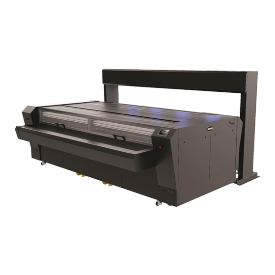
- Page 1 L3214 LASER CUTTER User Manual Rev 002...
- Page 2 FCC Notice The L3214 laser cutter has been tested and found to comply with the limits for Class A digital devices, pursuant to Part 15 of the FCC Rules. These limits are designed to provide reasonable protection against harmful interference when the equipment is operated in a commercial environment.
- Page 3 Registering the laser cutter Please register the L3214 laser cutter on the following link: https://www.summa.com/support/product-registration/ Failure to register the L3214 laser cutter may result in a delayed response to warranty and service inquiries. Contact Information All inquiries, comments or suggestions concerning this and other Summa manuals should be...
- Page 4 Even most intricate details are a breeze to cut with Summa laser cutting technology. Discover the many other advantages Summa laser cutting technology has to offer in this manual. Also, an overview of main components of the L3214, operating procedures and safety precautions are being explained in this manual.
-
Page 5: Table Of Contents
Table of Contents Safety ........................7 Safety ........................7 1.1.1 General ........................7 1.1.2 Symbols used in this manual .................. 7 1.1.3 Safety symbols on the machine ................8 1.1.4 Safety precautions ....................9 1.1.4.1 Danger area during operation ................. 9 1.1.4.2 Safety precautions related to movement .............. - Page 6 2.6.1 Extraction pump ....................31 2.6.2 Vacuum pump ....................... 31 Starting up the laser cutter ................32 Maintenance ......................33 Laser cutter ......................33 4.1.1 Optical components ....................34 4.1.1.1 Cleaning the static mirror ..................35 4.1.1.2 Cleaning the travelling mirror ................35 4.1.1.3 (Un)Installing the static and travelling mirrors ............
-
Page 7: Safety
L3214 Laser Cutter User’s Manual SAFETY Safety 1.1.1 General The manufacturer has no direct control over the machine operation and application. Proper safety practice is the sole responsibility of the owner, user, and operator. All instructions and safety warnings in this manual are based upon the use of this machine under proper operating conditions without alterations from the original design. -
Page 8: Safety Symbols On The Machine
L3214 Laser Cutter User’s Manual 1.1.3 Safety symbols on the machine Safety labels are used on some parts of the machine. They are explained below. Caution Servicing instructions are for use by qualified service personnel only. To reduce the risk of electric shock, do not open the equipment and do not perform any servicing other than that contained in the operating instructions unless you are qualified to do so. -
Page 9: Safety Precautions
Wear laser safety goggles. WARNING: Safety goggles must be worn. Any person or organization performing any modification to the L3214 laser cutting system is responsible for ensuring the reclassification and relabelling of the laser product. -
Page 10: Safety Precautions Related To The System Components
The electrical enclosure (i.e. doors and cover pods, etc.) must only be opened by trained service personnel. The L3214 laser cutting system must not be operated with its shutter, guard, protective housings, or any of the safety interlocks removed. -
Page 11: Safety Covers
L3214 Laser Cutter User’s Manual 1.1.5.2 Safety covers When the safety cover lid of the cutting area or the conveyor safety cover is opened, the laser stops firing and the cutting job is paused. A warning on the touch control panel pops up, prompting the operator to close the cover. -
Page 12: Laser Cutting System Components
L3214 Laser Cutter User’s Manual LASER CUTTING SYSTEM COMPONENTS Laser cutter Edge detection unwinder Water chiller Extractor fans (vacuum and fume extraction) Laser cutting system components... -
Page 13: Laser Cutter
L3214 Laser Cutter User’s Manual Laser Cutter Touch control panel Conveyor system with vacuum and fume extraction system underneath Finger safety conveyor cover Safety cover lid Emergency stop buttons Vision camera gantry Pressure rollers Feed button Light switch camera gantry and cutting area... -
Page 14: Touch Control Panel
L3214 Laser Cutter User’s Manual 2.1.1 Touch control panel The touch control panel is a unique interface system providing detailed cutter information and offering a flexible and powerful control of the cutter’s configuration. If applicable, tips or advice will be shown here. After a certain period of inactivity of the panel, the screensaver appears. -
Page 15: Settings Screen
L3214 Laser Cutter User’s Manual 2.1.1.2 Settings screen This screen allows viewing and changing the basic settings. 2.1.1.2.1 Parameters Standard Quality Quality Mode: The system supports three different quality modes: , and • Fine Detail . You can switch between these modes by clicking the current one. -
Page 16: Laser Test Fire Screen
L3214 Laser Cutter User’s Manual 2.1.1.3 Laser Test Fire Screen This screen is used to test-fire the laser and to cut straight lines manually. Tap to activate the move-and-fire action, then use the arrow keys in the left section to move the head around the cutting area while the laser is firing. -
Page 17: Media Area Screen
The new working area has now been set and the cutting head moves back to the bottom right corner of the working area. The working area values are shown below the Summa logo. Tap to confirm and apply your changes. -
Page 18: Conveyor System
2.1.6 Vision camera gantry The L3214 laser cutter is equipped with the Vision camera gantry. The Vision camera system uses integrated cameras to scan marks, black outlines, or barcodes, fast and accurately. It is also possible to scan, feed and cut at the same time. This camera system supports the following advanced work methods: •... -
Page 19: Light Switches
2.1.11 Ethernet connection Summa provides a computer in the right cabinet of the cutter, connected to the Ethernet connection on the rear of the cutter. 2.1.12 Main power switch... -
Page 20: Edge Detection Unwinder
L3214 Laser Cutter User’s Manual Edge detection unwinder A motorised unwinder eliminates fabric distortion while cutting by securing a constant and stable fabric feed onto the cutting bed. As the roll unwinds, a loop is created to relax the material, reducing distortion, and secure an accurate cut. This loop is kept constant with the use of the droop sensor or the tension bar. -
Page 21: Positioning The Unwinder
L3214 Laser Cutter User’s Manual 2.2.2 Positioning the unwinder The unwinder can only be installed after the laser cutter has been installed. The unwinder must be placed parallel, as central as possible in front of the back of the laser cutter, and as close as possible to avoid stretching the material. -
Page 22: Components
L3214 Laser Cutter User’s Manual 2.2.3 Components ON/OFF buttons Emergency stop button Control panel Media shaft Droop sensor Tension bar Edge detection sensor 2.2.3.1 Emergency stop buttons Pressing one of the emergency stop buttons will shut down the unwinder immediately. To... -
Page 23: Control Panel
L3214 Laser Cutter User’s Manual 2.2.3.2 Control panel Illuminated selector switch to System ready select the direction in which button. Flashes the fabric feeds from the roll when acknowledgement is loaded onto the media shaft. required. Press to acknowledge Switch to the center to place and activate the unwinder. -
Page 24: Droop Sensor And Tension Bar
L3214 Laser Cutter User’s Manual 2.2.3.3 Droop sensor and tension bar The edge detection unwinder is equipped with both a droop sensor and a tension bar, allowing you to choose how to keep the loop of relaxed material constant. When the tension bar is being used, the droop sensor isn’t, and vice versa. - Page 25 L3214 Laser Cutter User’s Manual 2.2.3.3.2 Material loop size adjustment (droop sensor) If the default settings are not appropriate and the distance from the sensor to the material loop needs to be adjusted, use the index plunger and/or loosen or tighten the small black screw on top of the sensor .
-
Page 26: Edge Detection Sensor
L3214 Laser Cutter User’s Manual 2.2.3.4 Edge detection sensor The edge detection sensor detects the edge of your material and triggers lateral movement of the unwinder carriage (with the roll of material) to ensure the material stays within the width of the conveyor. - Page 27 L3214 Laser Cutter User’s Manual 3. Secure the carriage by turning the knob again. Laser cutting system components...
-
Page 28: Air Pressure Media Shaft (Optional)
L3214 Laser Cutter User’s Manual Air pressure media shaft (optional) The optional air pressure media shaft can be expanded by means of air, thus preventing even the slightest play of the roll of material on the media shaft. The air gun for inflating the shaft is provided. -
Page 29: Loading The Roll Of Material On The Unwinder
L3214 Laser Cutter User’s Manual Loading the roll of material on the unwinder NOTE: We recommend handling the media shaft with two people. Perform the following steps to load the roll of material on the unwinder: Open the yellow safety covers on both sides of the media shaft and take the media shaft out of the unwinder. -
Page 30: Water Chiller
L3214 Laser Cutter User’s Manual Water Chiller 2.5.1 General Description A specialised laser water chiller performs water circulation cooling on the machine’s laser source and regulates its temperature to prolong its life. ATTENTION: Do not cover the cooler. Always make sure that air can enter the left-side filter and exit the right side unimpeded. -
Page 31: Vacuum And Fume Extraction System
L3214 Laser Cutter User’s Manual Vacuum and fume extraction system WARNING: Before commencing any cutting procedure, ensure that the fume extraction and vacuum system is in good working order and operates correctly. Some materials may produce hazardous fumes if laser cut – check with the material supplier or manufacturer before cutting. -
Page 32: Starting Up The Laser Cutter
L3214 Laser Cutter User’s Manual STARTING UP THE LASER CUTTER Check whether maintenance tasks need to be performed. For more information, see Maintenance chapter 4 on page 33. Make sure the power supply to the laser cutter is switched on. -
Page 33: Maintenance
L3214 Laser Cutter User’s Manual MAINTENANCE This chapter explains all maintenance works that need to be performed on the laser cutting system. A complete overview can be found on page 53. WARNING: Before performing any maintenance, disconnect the laser cutter from the main power supply. -
Page 34: Optical Components
L3214 Laser Cutter User’s Manual 4.1.1 Optical components To achieve maximum output from the laser cutter, the system’s optical components must be in good working order. REAR X RAIL HEAD MIRROR + FOCUSING LENS CUTTING AREA CUTTING HEAD COMBINING MIRROR... -
Page 35: Cleaning The Static Mirror
L3214 Laser Cutter User’s Manual 4.1.1.1 Cleaning the static mirror Remove the left-hand side cover of the laser cutter using a cross key to gain access to the static mirror. Apply a small amount of IPA optical cleaning solution onto the cleaning cloth provided in the tool kit and clean the mirror while in position. -
Page 36: Un)Installing The Static And Travelling Mirrors
L3214 Laser Cutter User’s Manual 4.1.1.3 (Un)Installing the static and travelling mirrors For removing the static and travelling mirror from their mount (e.g., in the event of a defect) and installing them again, use the spanner wrench (delivered in the toolbox). -
Page 37: Cleaning The Combining Mirror
L3214 Laser Cutter User’s Manual 4.1.1.4 Cleaning the combining mirror The combining mirror is located in between the laser source and the primary mirror. Its purpose is to redirect the laser pointer into the same path as the cutting laser. -
Page 38: Cleaning The Cutting Head Lens
L3214 Laser Cutter User’s Manual 4.1.1.5 Cleaning the cutting head lens The cutting head lens coating is fragile; do not drop the lens onto any hard surface or touch the lens with any sharp objects as this may damage the lens and reduce cutting efficiency. - Page 39 L3214 Laser Cutter User’s Manual Slide the barrel out. Remove the securing brass retaining screw by pressing your thumb against the brass and turning it counterclockwise. Carefully remove the rubber O-ring using a blunt plastic instrument, such as a tie wrap, or turn the tube upside down on to a clean moist cloth for the O-ring and lens to fall out.
- Page 40 L3214 Laser Cutter User’s Manual Apply IPA to the surface of the lens, allow the IPA to work into the dirt and gently wipe in one direction, then again at 90 degrees. Repeat this for both sides of the lens.
-
Page 41: Cleaning The Cutting Head Mirror
L3214 Laser Cutter User’s Manual 4.1.1.6 Cleaning the cutting head mirror Release (do not remove) the mirror securing screw holding the mirror securing clip, rotate the clip to release the mirror and place the cutting head on a clean flat surface. - Page 42 L3214 Laser Cutter User’s Manual Clean the nozzle while it’s out and remove any debris on the inside and outside. Inspect the mirror housing and clean the surface or lip where the mirror sits. Any dust on this surface will cause the mirror to seat incorrectly and may affect the alignment of the laser.
-
Page 43: Pneumatics
L3214 Laser Cutter User’s Manual 4.1.2 Pneumatics 4.1.2.1 Cleaning the nozzle To ensure proper airflow while cutting, the nozzle needs to be free of dirt. This step is preferably done with the barrel disassembled and the lens removed. 1. Remove the cutting head by releasing the M3 cap head screw and detaching the pneumatic tube. -
Page 44: Setting The Nozzle Height
L3214 Laser Cutter User’s Manual 4.1.2.2 Setting the nozzle height To have a clean cut a good focus of the laser beam is required. Depending on the nozzle, the thickness and the type of the material that is processed, height may vary. -
Page 45: Adjusting Airflow
L3214 Laser Cutter User’s Manual 4.1.2.3 Adjusting airflow Depending on the type of material being processed, an appropriate airflow must be present. 1. Find the pressure regulator in the right cabinet of the machine. 2. Check if all pneumatics tubes are still connected properly. -
Page 46: Cutting Head Drive Belt
L3214 Laser Cutter User’s Manual 4.1.3 Cutting head drive belt The cutting head drive belt is a toothed belt that carries the cutting head. It needs to be checked and cleaned periodically to ensure cleanliness. 1. Remove the rear poycarbonate cover for access to the Y-axis gearbox. -
Page 47: Conveyor Planks
L3214 Laser Cutter User’s Manual 4.1.4 Conveyor planks To ensure proper fume extraction and vacuum for material transportation, the conveyor planks need to be free of dust and lint. 1. Open the safety cover lid and visually inspect the conveyor planks for cleanness and damage. -
Page 48: Extraction System
L3214 Laser Cutter User’s Manual Extraction system To ensure proper fume extraction and vacuum in the cutting area, the extraction hoses need free of dust and debris. 1. Remove the vacuum hose from the extraction system (extraction fan, BOFA, or own system). -
Page 49: Chiller
L3214 Laser Cutter User’s Manual Chiller The laser unit is cooled with deionised water, to avoid bacterial infestation. 4.3.1.1 Water level The chiller needs a controlled water level to deliver full cooling capacity. 1. Check the water level through the inspection glass. The water level should be at least halfway. -
Page 50: Water Quality
L3214 Laser Cutter User’s Manual 4.3.1.2 Water quality Over time, the chiller water can become cloudy. Cloudy chiller water is no longer good for use. Replace with deionised water only. 1. Remove the reservoir cap. 2. Open the valve at the bottom of the chiller to drain all the chiller water. - Page 51 L3214 Laser Cutter User’s Manual 2. Drain the water from the damaged water hose. 3. Replace the water hose with a new one of the same length. 4. Refit the water hose into the chiller and open both valves completely.
-
Page 52: Air Filter
L3214 Laser Cutter User’s Manual 4.3.1.4 Air filter To ensure proper airflow through the chiller, the grid and the air filter need to be free of dust. The filter can be easily removed by hand. 1. Lift the filter and tilt outwards to slide it out. -
Page 53: Maintenance Overview
L3214 Laser Cutter User’s Manual Maintenance Overview ATTENTION: Make sure the power supply to the laser cutter is switched off before starting maintenance tasks! ATTENTION: In the tables below, we consider 8 operational hours per day (“1 Day"). For example, if there are two 8-hour shifts in a 24-hour period, this means that the component must be checked not once, but twice in those 24 hours (after each shift). - Page 54 L3214 Laser Cutter User’s Manual CHILLER Component Task Max. Interval Reference Water Level Check End User 1 Week Page 49 Water Quality Check End User 1 Week Page 50 Water Pipes Check End User 4 Weeks Page 50 Air Filter...
-
Page 55: Consumables
L3214 Laser Cutter User’s Manual CONSUMABLES The following accessories and consumables are available for the L3214 Laser Cutting System. Part description Part number Picture Standard 2.5” FL Lens 600-6028 Standard FB Mirror 600-6029 Diode Beam Combiner 600-6030 Optical Cleaning Fluid... -
Page 56: Troubleshooting
L3214 Laser Cutter User’s Manual TROUBLESHOOTING The laser is not cutting well in all areas of the bed: • The focus height is incorrect. • The lens is upside down. • The optics are in a poor state of cleanliness. -
Page 57: Error Messages
L3214 Laser Cutter User’s Manual Error Messages Error Message Possible Cause Checks Check if the front cover is closed. ERROR – FEED The conveyor cover Check if the left and right switches are being INTERLOCK (with sensor) is open. actuated correctly when closing the cover. -
Page 58: Gocare
L3214 Laser Cutter User’s Manual GOCARE The GoCare software allows upgrading the laser cutter firmware, making device and Vision camera backups, and restoring machine settings. The user manual of GoCare is available for download on our website (www.summa.com/en/support/user-manuals/). GoCare... -
Page 59: Go Produce Laser Edition
User’s Manual GO PRODUCE LASER EDITION Summa GoProduce Laser Edition is a Windows-based production software that integrates the L-Series into the workflow. It is the perfect link between the design station, RIP station, printers and cutting devices. Once the workflow is set up, macros automate the process.
Need help?
Do you have a question about the L3214 and is the answer not in the manual?
Questions and answers