Table of Contents
Advertisement
Quick Links
Advertisement
Table of Contents

Related Manuals for Summa L1810


Summary of Contents for Summa L1810
- Page 1 L1810 2 generation LASER CUTTER User Manual Rev 001...
- Page 2 User’s Manual FCC Notice The L1810 Gen2 laser cutter has been tested and found to comply with the limits for Class A digital devices, pursuant to Part 15 of the FCC Rules. These limits are designed to provide reasonable protection against harmful interference when the equipment is operated in a commercial environment.
- Page 3 Registering the laser cutter Please register the L1810 Gen2 laser cutter on the following link: https://www.summa.com/support/product-registration/ Failure to register the L1810 Gen2 laser cutter may result in a delayed response to warranty and service inquiries. Contact Information All inquiries, comments or suggestions concerning this and other Summa manuals should be...
- Page 4 Even most intricate details are a breeze to cut with Summa laser cutting technology. Discover the many other advantages Summa laser cutting technology has to offer in this manual. Also, an overview of main components of the L1810 Gen2, operating procedures and safety precautions are being explained in this manual.
- Page 5 L1810 2 generation User’s Manual Revision history Version Reason for modification Publication date Author Original version 31 March 2022 A.L.
-
Page 6: Table Of Contents
L1810 2 generation User’s Manual Table of Contents Safety ........................ 9 Safety ........................ 9 1.1.1 General ........................9 1.1.2 Symbols used in this manual ..................9 1.1.3 Safety symbols on the machine ................10 1.1.4 Safety precautions ....................11 Danger area during operation ................11 Safety precautions related to movement ............. - Page 7 L1810 2 generation User’s Manual General ......................... 27 Residual Risks ..................... 27 Noise ........................27 2.2.3 Positioning the unwinder ..................28 2.2.4 Standard unwinder ....................29 Components ......................29 2.2.4.1.1 Emergency stop buttons ..................29 2.2.4.1.2 Control panel ......................30 2.2.4.1.3...
- Page 8 L1810 2 generation User’s Manual Extraction systems ..................62 Maintenance Overview ................... 63 Consumables ....................65 Troubleshooting ..................... 66 Error Messages ....................67 Go Produce Laser Edition ................69 Installation and activation ................69 Firmware upgrade ................... 70 Standard program ................... 73 7.3.1...
-
Page 9: Safety
L1810 2 generation User’s Manual SAFETY Safety 1.1.1 General The manufacturer has no direct control over the machine operation and application. Proper safety practice is the sole responsibility of the owner, user, and operator. All instructions and safety warnings in this manual are based upon the use of this machine under proper operating conditions without alterations from the original design. -
Page 10: Safety Symbols On The Machine
L1810 2 generation User’s Manual 1.1.3 Safety symbols on the machine Safety labels are used on some parts of the machine. They are explained below. Caution Servicing instructions are for use by qualified service personnel only. To reduce the risk of electric shock, do not open the equipment and do not perform any servicing other than that contained in the operating instructions unless you are qualified to do so. -
Page 11: Safety Precautions
Wear laser safety goggles. WARNING: Safety goggles must be worn. Any person or organization performing any modification to the L1810 Gen2 laser cutting system is responsible for ensuring the reclassification and relabelling of the laser product. -
Page 12: Safety Precautions Related To The System Components
The electrical enclosure (i.e., doors and cover pods, etc.) must only be opened by trained service personnel. The L1810 Gen2 laser cutting system must not be operated with its shutter, guard, protective housings, or any of the safety interlocks removed. -
Page 13: Safety Cover Lid And Finger Safety Plates
L1810 2 generation User’s Manual Safety cover lid and finger safety plates When the safety cover lid of the cutting area is opened or the finger safety plates are triggered, the laser stops firing, and the cutting job is paused. A warning on the touch control panel pops up, prompting the operator to close the cover. -
Page 14: Laser Cutting System Components
L1810 2 generation User’s Manual LASER CUTTING SYSTEM COMPONENTS Laser cutter Unwinder Two air filtration units or one extraction fan Water chiller (if applicable) Laser cutting system components... -
Page 15: Laser Cutter
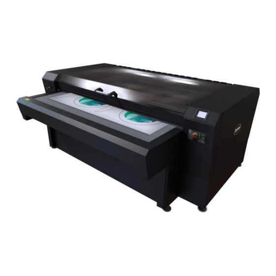
User’s Manual Laser Cutter L1810 Gen2 with front extension table and Vision camera system - front view L1810 Gen2 with front extension table and Vision camera system - rear view (1) Main power switch (8) Conveyor system (blade or honeycomb planks) -
Page 16: Main Power Switch
2.1.4 Ethernet connection If your laser cutter is equipped with the Vision camera system, Summa provides a computer in the right cabinet of the cutter, connected to the Ethernet connection on the rear of the cutter. If your laser cutter is not equipped with the Vision camera system, the computer (provided by the end-user) is connected with the cutter by means of a USB cable, running from the main board inside the cabinet along the underside of the machine to the external computer. -
Page 17: Touch Control Panel
L1810 2 generation User’s Manual 2.1.5 Touch control panel The touch control panel is a unique interface system providing detailed cutter information and offering a flexible and powerful control of the cutter’s configuration. If applicable, tips or advice will be shown here. After a certain period of inactivity of the panel, the screensaver appears. -
Page 18: Settings Screen
L1810 2 generation User’s Manual Settings screen Home Home 100 % 10 cm/s Maximum power Feed velocity 10 % High Minimum power Quality level More More 800 mm/s Velocity General 1000 mm/s Up velocity Calibrate touch screen Down acceleration Laser enable 0.8 g... -
Page 19: Parameters
L1810 2 generation User’s Manual 2.1.5.2.1 Parameters Maximum Power Minimum Power: For the calibration functions of the laser. Please • note that GoProduce Laser Edition overrides these settings when a job is sent: the maximum power and minimum power settings on the control panel only affect the calibration power of the laser. -
Page 20: Actions Screen
L1810 2 generation User’s Manual Actions Screen Home Reset Recut Feed Spot mode DIN A4 test Actions 2.1.5.3.1 Parameters • Reset: for clearing the last job sent from GoProduce Laser Edition to the laser. • Recut: for resending the last job sent from GoProduce Laser Edition to the laser. -
Page 21: Set Origin Screen
L1810 2 generation User’s Manual Set Origin Screen Set origin Cancel Reset X: 0 Y: 0 Apply Access this screen by clicking in the home screen. The X and Y coordinates are displayed in the centre of the screen so that you can choose an exact origin if required, for example if you require using a jig. -
Page 22: Media Size Screen
L1810 2 generation User’s Manual Media Size Screen Media size Cancel Reset X: 0 Y: 0 Apply After having set the origin, this screen appears. The X and Y coordinates are displayed in the centre of the screen so that you can choose an exact media size if required, for example if you require using a jig. -
Page 23: Pause Screen
L1810 2 generation User’s Manual Pause Screen Pause Resume When paused and if you wish to check the cut quality, tap the arrows to move the cutting head away from the cut material. Resume to move the cutting head back to its previous position and resume cutting. -
Page 24: Conveyor System
L1810 2 generation User’s Manual 2.1.8 Conveyor system The conveyor system, equipped with honeycomb or blade conveyor planks, transports the material through the working area and then out of the machine. The material is held down by the vacuum/extraction system underneath the conveyor bed, resulting in a clean cut and precise material transport. -
Page 25: Cutting Head Nozzle
L1810 2 generation User’s Manual 2.1.10 Cutting head nozzle The cutting head nozzle emits the laser beam that cuts the material in the cutting area. Nozzle height To have a clean cut a good focus of the laser beam is required. As a rule of thumb, we set the nozzle 4mm above the material. -
Page 26: Head Camera
L1810 2 generation User’s Manual 2.1.11 Head camera The laser cutter is always equipped with a head camera. When desired, the head camera can be used for the following advanced work methods: • Cut-to-Frame (also known as Fixed Size cutting) •... -
Page 27: Unwinder (Optional)
L1810 2 generation User’s Manual Unwinder (optional) 2.2.1 General Description A motorised unwinder eliminates fabric distortion while cutting by securing a constant and stable fabric feed onto the cutting bed. As the roll unwinds, a loop is created to relax the material, reducing distortion, and secure an accurate cut. -
Page 28: Positioning The Unwinder
L1810 2 generation User’s Manual 2.2.3 Positioning the unwinder The unwinder can only be installed after the laser cutter has been installed. The unwinder must be placed parallel, as central as possible in front of the back of the laser cutter, and as close as possible to avoid stretching the material. -
Page 29: Standard Unwinder
L1810 2 generation User’s Manual 2.2.4 Standard unwinder Components ON/OFF buttons Emergency stop button Control panel Media shaft Droop sensor 2.2.4.1.1 Emergency stop buttons Pressing one of the emergency stop buttons will shut down the unwinder immediately. To... -
Page 30: Control Panel
L1810 2 generation User’s Manual 2.2.4.1.2 Control panel Illuminated selector switch to select the direction in which the fabric feeds from the roll loaded onto the media System ready button. shaft. Switch to the center to place the Flashes when unwinder in park mode (standby). -
Page 31: Droop Sensor
L1810 2 generation User’s Manual 2.2.4.1.3 Droop sensor The droop sensor detects when the unwinder has reeled enough slack material to feed the laser cutter when required. In other words, as the roll of material unwinds, a loop of relaxed material is created, reducing distortion, and securing an accurate cut. -
Page 32: Edge Detection Unwinder
L1810 2 generation User’s Manual 2.2.5 Edge detection unwinder Components ON/OFF buttons Emergency stop button Control panel Media shaft Droop sensor Tension bar Edge detection sensor 2.2.5.1.1 Emergency stop buttons Pressing one of the emergency stop buttons will shut down the unwinder immediately. To... -
Page 33: Control Panel
L1810 2 generation User’s Manual 2.2.5.1.2 Control panel Illuminated selector switch to select the direction in which the fabric feeds from the roll loaded onto the media shaft. Switch to the center to place the unwinder in Error LED. Flashes in park mode (standby). -
Page 34: Droop Sensor And Tension Bar
L1810 2 generation User’s Manual 2.2.5.1.3 Droop sensor and tension bar The edge detection unwinder is equipped with both a droop sensor and a tension bar, allowing you to choose how to keep the loop of relaxed material constant. When the tension bar is being used, the droop sensor isn’t, and vice versa. - Page 35 L1810 2 generation User’s Manual 2.2.5.1.3.2 Material loop size adjustment (droop sensor) If the default settings are not appropriate and the distance from the sensor to the material loop needs to be adjusted, use the index plunger and/or loosen or tighten the small black screw on top of the sensor .
-
Page 36: Edge Detection Sensor
L1810 2 generation User’s Manual 2.2.5.1.4 Edge detection sensor The edge detection sensor detects the edge of your material and triggers lateral movement of the unwinder carriage (with the roll of material) to ensure the material stays within the width of the conveyor. - Page 37 L1810 2 generation User’s Manual 3. Secure the carriage by turning the knob again. Laser cutting system components...
-
Page 38: Loading The Roll Of Material On The Unwinder
L1810 2 generation User’s Manual 2.2.6 Loading the roll of material on the unwinder NOTE: We recommend performing this procedure with two people. Perform the following steps to load the roll of material on the unwinder: Open the yellow safety covers on both sides of the media shaft and take the media shaft out of the unwinder. -
Page 39: Fume Extraction System
L1810 2 generation User’s Manual Fume extraction system WARNING: Before commencing any cutting procedure, ensure that the fume extraction system is in good working order and operates correctly. Some material may produce hazardous fumes if cut using the laser – check with the material supplier or manufacturer before cutting. -
Page 40: Water Chiller (Optional)
Water chiller (optional) NOTE: The information in this chapter only applies to the water chiller supplied by Summa. If another water chiller is used, this information is not applicable, and you should refer to the supplier's documentation of your water chiller. -
Page 41: Starting Up The Laser Cutter
Switch on the power supply to the laser cutter. Power on the laser cutter. The control panel displays the Summa splash screen for several seconds. The loading screen is displayed, and the motion system moves to its home position. If one of the covers is open, however, the motion system does not move and the “Close cover!”... -
Page 42: Maintenance
L1810 2 generation User’s Manual MAINTENANCE This chapter explains all maintenance works that need to be performed on the laser cutting Maintenance Overview system. A complete overview can be found in chapter 4.5 on page 63. WARNING: Before performing any maintenance, disconnect the laser cutter from the main power supply. -
Page 43: Optical Components
L1810 2 generation User’s Manual 4.1.1 Optical components To achieve maximal output from the laser cutter, the system’s optical components must be in good working order. Cutting Area The optics must be handled with care and cleaned only with optical cleaning solution and an optical grade polishing cloth. -
Page 44: Primary Mirror
L1810 2 generation User’s Manual Primary mirror Remove the left-hand side cover of the laser cutter using a cross key to gain access to the primary mirror. Apply a small amount of IPA optical cleaning solution onto the cleaning cloth provided in the tool kit and clean the mirror while in position. -
Page 45: Secondary Mirror
L1810 2 generation User’s Manual Secondary mirror 1. Open the safety cover lid. 2. Remove the four bottom screws of the front guard and open it. 3. Apply a small amount of IPA optical cleaning solution onto the cleaning cloth provided in the tool kit and clean the mirror while in position. -
Page 46: Cutting Head Lens
L1810 2 generation User’s Manual Cutting head lens The cutting head lens coating is fragile; do not drop the lens onto any hard surface or touch the lens with any sharp objects as this may damage the lens and reduce cutting efficiency. - Page 47 L1810 2 generation User’s Manual Remove the lens ring by turning it counterclockwise. Carefully drop the lens onto a clean microfibre cloth. WARNING: Ensure that the area is sufficiently ventilated. The solvent should be kept away from heat or flames. Wear appropriate clothing and safety goggles.
- Page 48 L1810 2 generation User’s Manual This is a good time to also clean the nozzle. For more information, refer to chapter 4.1.2.1 Nozzle cleaning on page 51. Hold the edges of the lens with the convex surface facing upward and carefully place it into the nozzle barrel.
-
Page 49: Cutting Head Mirror
L1810 2 generation User’s Manual Cutting head mirror Remove the cutting head by releasing the M4 screw and detaching the pneumatic tube. Release (do not remove) the mirror securing screw holding the mirror securing clip. Rotate the clip to release the mirror. - Page 50 L1810 2 generation User’s Manual Gently rotate the head so that the mirror falls out onto a microfibre cleaning cloth. Apply IPA optical cleaning solution to the mirror face and let it soak for a few seconds. Gently lay an optical cleaning solution cloth on one edge of the mirror and gently draw the cloth right across the mirror in one continuous movement.
-
Page 51: Pneumatics
L1810 2 generation User’s Manual 4.1.2 Pneumatics Nozzle cleaning To ensure proper airflow while cutting, the nozzle needs to be free of dirt. This step is preferably done while the barrel is disassembled, and the lens is removed. Remove the cutting head by releasing the M4 screw and detaching the pneumatic tube. -
Page 52: Airflow
L1810 2 generation User’s Manual Airflow Depending on the type of material being processed, an appropriate airflow must be present. Find the pressure regulator at the back of the machine. Check if all pneumatics tubes are still connected properly. Check the pressure gauge to see if it is set properly: range between 0.5 bar (7.2psi) and 3 bar (43.51psi). -
Page 53: Axes
L1810 2 generation User’s Manual 4.1.3 Axes Axis movement Set Origin Check smooth movement on both axes. Use the arrow keys at the screen to move the cutting head to each corner of the cutting bed and check for any irregularities. For more... -
Page 54: Air Filters
L1810 2 generation User’s Manual 4.1.4 Air filters To protect the internal components from surrounding dust particles, three filters are fitted around the machine. Open the left and the right cover using the cross key. Remove the filter from the left/right cover and the back panel. -
Page 55: Conveyor Planks
L1810 2 generation User’s Manual 4.1.5 Conveyor planks To ensure proper fume extraction and vacuum for material transportation, the conveyor planks need to be free of dust and lint. Open the safety cover lid and visually inspect the conveyor planks for cleanness and damage. -
Page 56: Air-Cooled Laser
L1810 2 generation User’s Manual Air-cooled laser This section is only applicable if an air-cooled laser unit is installed inside the laser cutter. Check the serial number label on the back right of the machine. An air-cooled laser cutting /100 machine type ends with 4.2.1... -
Page 57: Water-Cooled Laser
L1810 2 generation User’s Manual Water-cooled laser This section is only applicable if a water-cooled laser unit is installed inside the laser cutter. Check the serial number label on the back right of the machine. A water-cooled laser cutting /120... -
Page 58: Chiller
L1810 2 generation User’s Manual 4.3.2 Chiller The laser unit is cooled with deionised water, to avoid bacterial infestation. Water level The chiller needs a controlled water level to deliver full cooling capacity. 1. Check the water level through the inspection glass. The water level should be at least halfway. -
Page 59: Water Quality
L1810 2 generation User’s Manual Water quality Over time, the chiller water can become cloudy. Cloudy chiller water is no longer good for use. Replace with deionised water only. Remove the reservoir cap. Open the valve at the bottom of the chiller to drain all the chiller water. -
Page 60: Water Pipes
L1810 2 generation User’s Manual Water pipes To ensure proper water flow, the water hoses need to be in good condition and without kinks or sharp bends. Close the valves on the chiller. Drain the water from the damaged water hose. -
Page 61: Chiller Air Filter
L1810 2 generation User’s Manual Refit the water hose into the chiller and open both valves completely. Chiller air filter To ensure proper airflow through the chiller, the grid and the air filter need to be free of dust. The filter can be easily removed by hand. -
Page 62: Extraction Systems
L1810 2 generation User’s Manual Extraction systems To ensure proper fume extraction and vacuum in the cutting area, the extraction hoses need free of dust and debris. Remove the vacuum hose from the extraction system (extraction fan, BOFA, or own system). -
Page 63: Maintenance Overview
L1810 2 generation User’s Manual Maintenance Overview ATTENTION: Make sure the power supply to the laser cutter is switched off before starting maintenance tasks! ATTENTION: The intervals below should be considered as the maximum allowed time between maintenance tasks. If a component requires the performance of a maintenance task sooner than indicated below, do not delay. - Page 64 L1810 2 generation User’s Manual WATER-COOLED LASER Component Task Interval Reference Chiller Water Level Check End User 1 Week Page 58 Chiller Water Quality Check End User 1 Week Page 59 Chiller Water Pipes Check End User 4 Weeks Page 60...
-
Page 65: Consumables
L1810 2 generation User’s Manual CONSUMABLES Part Number Description 600-6028 Standard 2,5' FL Lens 600-6029 Standard FB Mirror 600-6034 Optical Cleaning Fluid 600-6035 Optics Cleaning Cloth 600-6053 Alignment Targets 600-6055 Laser Safety Glasses 600-6132 100 mm R/Tyred Wheel Unwinder 600-6133... -
Page 66: Troubleshooting
L1810 2 generation User’s Manual TROUBLESHOOTING The laser is not cutting well in all areas of the bed: • The focus height is incorrect. • The lens is upside down. • The optics are in a poor state of cleanliness. -
Page 67: Error Messages
L1810 2 generation User’s Manual Error Messages Error Possible Checks Corrective Action Message Cause Material Check affected area for any Object loose material, objects or thread Remove any debris from obstructing that have become moving parts movement entangled in moving parts... - Page 68 L1810 2 generation User’s Manual Error Possible Checks Corrective Action Message Cause End-of-roll Check if material loop covers the Unwind material until sensor sensor sensor is covered unwinder uncovered De-reeler Interlock Check all interlock switches and Replace repair Material switch...
-
Page 69: Go Produce Laser Edition
User’s Manual GO PRODUCE LASER EDITION Summa GoProduce Laser Edition is a Windows-based production software that integrates the L-Series into the workflow. It is the perfect link between the design station, RIP station, printers and cutting devices. Once the workflow is set up, macros automate the process. -
Page 70: Firmware Upgrade
L1810 2 generation User’s Manual Firmware upgrade You can check the cutter’s current firmware version via the touch panel when tapping in the home screen. To perform a firmware upgrade, you will need: • The latest firmware revision • The GoCare software Both can be searched and downloaded via https://www.summa.com/en/support/software-... - Page 71 L1810 2 generation User’s Manual Device – Upgrade firmware 3. Click on the set. The following screen appears. 4. Browse for the firmware downloaded from our website and click Next. The following screen appears. Once the laser cutter received the firmware file, upgrade starts automatically. You can follow the progress on the computer screen (GoCare) and on the touch panel.
- Page 72 L1810 2 generation User’s Manual 5. Once the upgrade is completed, the following screen appears. Finish 6. Click and reboot the laser cutter. Go Produce Laser Edition...
-
Page 73: Standard Program
7.3.1 Main window The window of the program Summa GoProduce Laser Edition has 4 main areas. The ribbon contains 5 tabs. At the left side, there is a docked window with the action sets. On the right side, there is a docked window with layer information. In the middle, a job preview will be shown. -
Page 74: Quick Access Toolbar
L1810 2 generation User’s Manual 7.3.2 Quick access toolbar The commands of the quick access toolbar are displayed in the title bar: undo, redo, cut, copy, and paste. 7.3.3 Ribbon The ribbon has 5 tabs. Job tab This tab gives access to some basic editing functions, so the job can be optimized to cut. Most of those functions can be included in the import action set. - Page 75 L1810 2 generation User’s Manual You can either scan all layers or fill in the name of a specific layer. Also, the shape and size of the registration mark can be set. Set all the parameters to the desired value and click OK.
-
Page 76: Selection Tab
L1810 2 generation User’s Manual This function removes double objects. Nothing needs to be selected; the function selects all objects (closed curves) automatically and deletes any double objects. The maximum distance can be set by right-clicking the icon. Use this to reveal the orientation of the object. Click it and a triangle will be shown at the start point of each object, showing the direction of the curve. -
Page 77: Material Manager Tab
Some RIPs will have the possibility to select the material when the job is printed. In that case, it will not be necessary to choose the material type again in Summa GoProduce Laser Edition. This tab is not used when processing a job: it is used to predefine settings for different materials. -
Page 78: Materials
7.3.3.3.1 Materials Set the selected material as default material. If the file with the cut data does not have a material defined in it, Summa GoProduce Laser Edition will automatically use the default material. Create a material. Import a material. Several predefined materials are available. - Page 79 L1810 2 generation User’s Manual Methods • are chosen in the design program and are linked to a certain tool suitable for this material. • Tools: Click the cross-hatched area of a method to see which tool is linked to it.
-
Page 80: Methods
There are a couple of standard camera profiles installed when Summa GoProduce Laser Edition is installed. One camera profile can usually be used for a large range of materials. -
Page 81: Devices
L1810 2 generation User’s Manual Create a camera profile (ideally after having started a cutting job, so you can set the parameters according to the preview of the job that is shown on the screen). Import a camera profile. Edit the selected camera profile (ideally after having started a cutting job, so you can set the parameters according to the preview of the job that is shown on the screen). -
Page 82: General
L1810 2 generation User’s Manual General The fifth tab in the ribbon holds some general parameters and settings. Click this icon for information about the program. Also, the license manager is opened to add more licenses for extra options. Backup... -
Page 83: Action Sets
Action sets can be workflows or a group of often recurring editing functions that determine what happens with the material that needs to be cut. When Summa GoProduce Laser Edition is installed, a few default action sets are installed as well. -
Page 84: List Of Available Actions
L1810 2 generation User’s Manual List of available actions 7.3.4.2.1 Clean-up Break at intersections: This action breaks curves at intersections. You can also regard objects as intersections when they are very close to one another. The maximum distance for being regarded as intersection or not can be set. - Page 85 L1810 2 generation User’s Manual folder: Only available with the Pro Pack. The hot folder system is specifically useful when the design software is located on another computer in the network. Because in this case, the plug-ins cannot be used. Files dropped in a folder can now also be opened automatically in GoProduce Laser Edition.
- Page 86 L1810 2 generation User’s Manual Sorting mode: • There are three basic sorting methods to control the order in which objects are cut: Sorting by the main direction in the length direction, sorting by the main direction in the width direction, or sorting by nearest objects. The aim of sorting is to reduce the cutting time by having to move as little as possible.
-
Page 87: Job
L1810 2 generation User’s Manual Plot to file: This outputs the cutting job to a file instead of to the laser cutter. We do not • recommend checking this option. Direct mode: If this option is checked, the program will not show the output parameters as •... -
Page 88: Predefined Actions Sets
User’s Manual Predefined actions sets When Summa GoProduce Laser Edition is installed, certain pre-defined actions sets are installed by default: • Import file • Clean-up design (Note that using this option might leave you with a lot of open curves since double lines will be deleted, which can influence the sorting algorithms. -
Page 89: Creating Action Sets
L1810 2 generation User’s Manual Creating action sets 1. Click to create an action set. The following window appears. 2. Name the action set, describing clearly what it is used for. You can also add a description to add extra information and choose another logo for the action set by clicking the default logo 3. -
Page 90: Layers Window
The Layers window on the right shows the material, method, and tool settings. If the RIP has a driver for Summa GoProduce Laser Edition and the settings in the RIP are correct, all the information in this window is automatically chosen as soon as the file with the cut data is imported. -
Page 91: Set Materials
L1810 2 generation User’s Manual Create a layer. Show only the selected layer. Hide only the selected layer. Select all objects on the selected layer. Move al current objects to the selected layer. Delete the selected layer. Lock or unlock this layer. -
Page 92: Set Camera Profiles
L1810 2 generation User’s Manual Set camera profiles If the methods are set correctly in the cut data file, the camera profile should automatically be set correctly. If you want to use another camera profile, you can select it from the drop-down list... -
Page 93: Case 2 Material Not Set Correctly / Wrong Method Chosen For Material
L1810 2 generation User’s Manual Sometimes a list is available, situated next to the tool type, with predefined parameter sets for the chosen tool. The default setting will always be chosen, but alternative parameter sets (if available) can be chosen here. -
Page 94: Advanced Work Methods
L1810 2 generation User’s Manual Advanced work methods Cut-to-Frame (requires head camera or Vision camera system) Also known as Fixed Size Cutting, this functionality enables a perfect fit into SEG (Silicone Edge Graphics) frames. Any shrinkage and deformations that occurred during printing and calendering are automatically detected. -
Page 95: Pro Pack (Optional)
In this case, before starting the workflow, check the setting of the default material and change if needed. Barcode workflow action sets There are two barcode workflow action sets that can be imported from ..\\Documents\Summa GoProduce Laser Edition\Action sets: • Barcode workflow on roll •...
Need help?
Do you have a question about the L1810 and is the answer not in the manual?
Questions and answers