Table of Contents
Advertisement
Quick Links
Advertisement
Table of Contents

Related Manuals for Summa L1810


Summary of Contents for Summa L1810
- Page 1 User Manual REV. 2 Rev.2...
- Page 2 L1810 User’s Manual Description Date Created Manual without vision 17/3/2021 Added vision and re-organized content 26/5/2021 REV. 2...
- Page 3 DOC Notice The L1810 Laser cutting system do not exceed the Class A limits for radio noise for digital apparatus, set out in the Radio Interference Regulations of the Canadian Department of Communications.
- Page 4 Registering the Laser cutting system Please register the L1810 Laser cutting system on the following link: https://www.summa.com/support/product-registration/ Failure to register the L1810 Laser Cutting System may result in a delayed response to warranty and service inquiries. Contact Information All inquiries, comments or suggestions concerning this and other Summa manuals should...
- Page 5 Welcome Congratulations on Your Purchase of the New L1810 Laser Cutting Systems The L1810 Laser cutting system are capable of cutting soft signage applications as well as roll stock. Textile is one of the fastest growing markets nowadays, where on-demand digital printing proved to be the game changer many soft signage, sportswear and fashion brands need.
-
Page 6: Table Of Contents
L1810 User’s Manual Table of Contents Overview ....................... 1-9 1.1 Operating environment..................1-9 Safety ........................2-10 2.1 General ......................2-10 2.2 Symbols used in this manual ................2-10 2.3 Safety Information ..................2-11 2.4 Ventilation ...................... 2-11 2.5 Noise ....................... 2-11 2.6 Fire Precautions.................... - Page 7 L1810 User’s Manual 4.1 Safety Information ..................4-24 4.1.1 General ....................4-24 4.1.2 Residual Risks ..................4-24 4.1.3 Noise......................4-24 4.2 Overview of the Auto Tracking De-Reeler ............. 4-24 4.3 Positioning and Levelling ................4-24 4.4 De-Reeler Components .................. 4-25 4.4.1 Control board ..................
- Page 8 L1810 User’s Manual 6.2.2 Compressed Air Feed to the Cutting Head ..........6-64 6.2.3 Temperature Display and Thermostat Controller ........6-64 6.3 Extraction System ................... 6-65 6.3.1 Description ....................6-65 6.3.2 2x Extraction Unit Checklist ..............6-65 6.3.3 2x 3 Phase Fan @480V AC Speed Controller .......... 6-66 6.3.4 Maintenance of All Fan Units ..............
-
Page 9: Overview
L1810 User’s Manual OVERVIEW Operating environment Environmental conditions can significantly affect the machine’s performance. Most restrictions or recommendations for the ideal operating environment are already described in the site preparation document. The environmental conditions of the machine (without media) are as follows: Operating Temperature 15 to 32... -
Page 10: Safety
L1810 User’s Manual SAFETY General The purpose of the user’s operator procedure is to explain the operating procedures in order to operate this machine. It also provides the owner, users and operators with precaution procedures for safe and proper machine operation for its intended purpose. -
Page 11: Safety Information
Any person or organization performing any modification to the L1810 Laser cutting system is responsible for ensuring the reclassification and relabeling of the laser product. The L1810 Laser cutting system must not be operated with any of the safety interlocks, shutter, guard or protective housings removed. Before commencing any cutting procedure ensure that the fume extraction system is in good working order and operates correctly. -
Page 12: Extraction System
L1810 User’s Manual emission will be generated if any of the following materials are processed (this is not an exhaustive list and each material must be chosen for its suitability for laser processing): Leather and artificial leather that contains chromium (VI) •... -
Page 13: Emergency Buttons/Safety Covers
L1810 User’s Manual Emergency buttons/safety covers The L1810 has four emergency buttons that shut down the machine immediately. • Once an emergency button is pressed, the unit needs to be rebooted. It is recommended to reboot the software as well. -
Page 14: Working Area
L1810 User’s Manual Working area Danger Area During Operation FIG 2-1:YELLOW MARKS ARE DANGER AREA The easiest way to define the general danger area is the complete area where the conveyor is running and the fabric roll is in motion. The red zone area is the normal production area. -
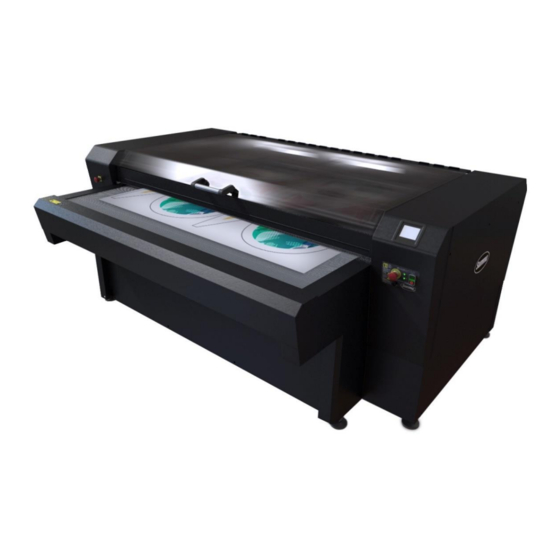
Page 15: Main Unit
L1810 User’s Manual MAIN UNIT Components REV. 2 3-15... - Page 16 L1810 User’s Manual 1. Main keyboard Please wait! Loading... 2 Conveyor 2. Front Safety Cover 3. Safety cover 4. Emergency buttons REV. 2 3-16...
-
Page 17: Touchscreen Control Panel
The easiest way to learn about the touch screen how to use it. Touch Input The touchscreen provides an interactive experience for managing L1810. It provides a simple, safe, and connected experience as a part of your system. The feature and service icons appear on the touch screen, by touching an icon, button, or control displayed on the screen, you can directly access the corresponding feature and service. -
Page 18: System Start-Up
Home Position’ moves to the ‘ . The cover of the L1810 must be closed for the machine to return to the Home Position. When the motion system has fully homed the Touch Screen will display Home Screen’... -
Page 19: Home Screen
L1810 User’s Manual Home Screen Home Screen’ The ‘ is the main Touch Screen display and most functions are accessible from here. 3.2.5.1 Home Home Home Screen Press the ‘ ’ button to return to the ‘ ’. 3.2.5.2 Set media area... -
Page 20: Settings
Revision: L01 Build: Jan 16 2017 Settings Settings Screen Press the ‘ ’ button to access the main ‘ ’ for the L1810. Settings Settings Screen In the ‘ ’ you are able to change a number of settings that More control the speed, acceleration, laser power and calibrations. -
Page 21: Actions
• Please note that Ethos (Cutting Software) overrides these settings when a job is sent to the L1810. The Velocity Setting at the Touch panel only affects the Calibration functions of the laser. Up Velocity This affects the non-cutting speed of the motion system. -
Page 22: Feed Conveyor
Press the ‘Reset’ button to clear the last job sent to the Laser from Ethos. Recut Press the ‘Recut‘ button to re-send the last job sent to the L1810 from ‘Ethos’. Feed Press the ‘Feed‘ button to manually feed the Roll Feed or Conveyor on the L1810. - Page 23 L1810 User’s Manual REV. 2 3-23...
-
Page 24: Reeler
L1810 User’s Manual DE-REELER This document provides information and instructions on how to load material onto the De- Reeler and how to use the controls and sensors to for best performance. Safety Information General The De-Reeler should only be used for feeding the laser system with synthetic or natural material. -
Page 25: Reeler Components
L1810 User’s Manual De-Reeler Components Control board De-Reeler The controls located on the top right of the are used to operate and set the initial positions for material handling after loading a new roll. EMERGENCY STOP De-Reeler - Press this button to immediately STOP the . -
Page 26: Sensors And Reflector
L1810 User’s Manual Sensors and Reflector Tracking 4.4.2.1 De-Reeler Material Droop Sensor and Reflector sensors The Droop Sensor is located on the rear of De-Reeler and is used to detect when De-Reeler has reeled enough slack DROOP L1810 material for the... - Page 27 L1810 User’s Manual REV. 2 4-27...
-
Page 28: Operations
L1810 User’s Manual OPERATIONS Loading the Fabric Roll REV. 2 5-28... -
Page 29: Controlling The Cutter With Material Effects
L1810 User’s Manual Controlling the Cutter with Material Effects Material Effects Overview Material effects are used to control the cutter. They can control the speed, power and number of passes, and if required, can be related to specific materials. Material effects are automatically applied to designs as they are cut, unless a Material Effect has been assigned. -
Page 30: Material Effects When Using Laser Cutters
User’s Manual Material Effects when using Laser Cutters Material effects are extremely important when cutting materials on the Summa L1810. They control both the quality and depth of cut by setting the cutting speed, number of passes and power output of the laser. Material effects can be assigned to and saved with each design. -
Page 31: Effects
L1810 User’s Manual Effects This form allows materials and related effects to be created and edited. FIG 5-1 ApS-Ethos will already contain some standard material effects for both vinyl and laser cutters. Effects can be created by either 'Effect 'or 'Material .' For instance, you can create or select an effect and then assign it to a particular material. -
Page 32: Creating New Effects
L1810 User’s Manual FIG 5-2 A new blank entry will appear under Materials with the flashing cursor. Enter a title for your material and when you press 'enter 'the new material will be created. Once a new material is created, all of the existing effects will automatically be related to that material, using the current settings for 'Paper .' It is now possible to edit the effects to the... -
Page 33: Assigning Effects
The velocity can be increased/decreased in steps of 1mm per second. The maximum linear speed of the L1810 laser is 1500 mm per second. Maximum Power - The maximum power output of the laser during cutting. If the cut •... -
Page 34: Working With Templates
L1810 User’s Manual By selecting the Driver Effect combo a list of installed cutters will appear. Select the cutter to be used and the Effects tree control will appear in the dialogue. Select effects and then select the effect to be applied. On the effect palette section select the colour the effect is to be assigned to, then select Set. -
Page 35: Create A New Template
L1810 User’s Manual will provide guidance with the planning and scaling of a design. The data contained in a template can, if you wish, be ignored when the design is cut. Templates can also contain material effects which will simplify assigning effects. Also, if you set up a template containing your regularly used effects, you will soon get to know which colour relates to each effect, so you can use them as a standard. - Page 36 L1810 User’s Manual The Save As dialogue box will display giving you the opportunity to name your template. FIG 5-8 When you select OK the template will be saved ready for future use. REV. 2 5-36...
-
Page 37: Vision System
L1810 User’s Manual Vision system The vision system is optional, when the L1810 does not have a vision system skip this chapter and continue to chapter 7 : file preparation. Contour Vision Registration Marks 1. Start Aps-ethos software and select Design-Open 2. - Page 38 L1810 User’s Manual About Templates: Templates are work platforms which are very useful. They contain material information, effects, output settings, etc. If templates are setup correctly, according to how the cutting data is generated, the operator can launch the job without any manipulation, setting change or whatever.
- Page 39 L1810 User’s Manual To change the effect, click on the drop down list and select the preferred effect. REV. 2 5-39...
- Page 40 L1810 User’s Manual Tips: To select all objects of one colour: Hold down the ‘N’ key and click on an object with the wanted colour. Go to View and activate snapshot, click on the view used colour icon FIG 5-9 Now you see an overview off all colours/effect used in the design.
- Page 41 L1810 User’s Manual 6. Make sure all is secure around the machine and Click on ‘SCAN’ 7. A first ‘bite’ will be scanned (or images from memory will be loaded). A preview of the scan will appear, when hovering over the scan a magnifier will pop up to see more detail.
- Page 42 If a mark is indicated, position information is show here. With the ‘Go To’ button, the magnifier will be centred on this position. Find automatically: not implemented on the L1810 Cutter Settings: Cutter Settings are saved in the template: Select Material.
- Page 43 Size compensation: The size will be correct, but small deformations are done to follow media shifts on the table. Copies/Repeats To cut the same job a few times after each other use this functionality. NOTE: Detect Gap Automatically is not functional on the L1810 REV. 2 5-43...
- Page 44 L1810 User’s Manual Cutting Offset FIG 5-10 The print & cut calibration is very detailed, and doing a complete calibration is outside the scoop of this document. A simple shift over the complete job can be achieved by using the cutting offset.
- Page 45 L1810 User’s Manual NOTE: if a message appears that the marker could not be found, adjust the threshold as explained before: After the first mark is indicated the ‘Cut’ button is active. Click on ‘Cut’ to process the complete job.
-
Page 46: Contour Cut Vision (Trace)
L1810 User’s Manual Reset Reset will do exactly the same as closing the vision window and going back in. If scans are in memory, there will be a request to load them or not. If no scans from history are loaded, the scan button will activate a complete new scan. - Page 47 L1810 User’s Manual 3. On the right hand side, press ‘SCAN’ from the actions panel. Position the material forwards or backwards as necessary until the first pieces are visible in the scan window. 4. Settings: REV. 2 5-47...
- Page 48 L1810 User’s Manual Margins To set the ‘Margin’(s), click in the edit box for that margin. An asterisk will appear beside the selected edit box. A new value can be typed now. The number shown in the edit box is the distance in millimeters from the corresponding scan edge.
- Page 49 L1810 User’s Manual 1. Select Left Margin 2. Select Right Margin 3. Select Bottom Margin The dark blue line in the magnifier indicates where the ‘Margin’ will be set. If you are happy with this location, click to accept it. If the ‘Margin’ was already set, its current location is given by a cyan line.
- Page 50 L1810 User’s Manual Cut Waste This function will automatically ‘Cut Waste’ material from the roll in a horizontal line. This is useful to prevent the waste material snagging the roll and moving the fabric from its scanned position. Additionally it produces more manageable sizes of waste material. You are able to set the number of bites the ‘Cut Waste’...
-
Page 51: File Preparation
L1810 User’s Manual File preparation Manual Placement of Registration Marks Registration Mark size: 2 - 3mm (normally 2mm is sufficient) Positioning of mark: Distance from Reg Mark to shapes: 10mm minimum. This is to make sure that the camera does not pick up the printed shape and get confused. -
Page 52: Using The Toolbar In Ethos To Create Registration Marks
L1810 User’s Manual NOTE: The grid does not need to be symmetrical as indicated above. Different distances can be used between marks. However, this would complicate the explanation. For our cutting software please save the cutting marks and contour to either a PDF, AI or EPS file. -
Page 53: Toolbar Functions
L1810 User’s Manual The registration Mark Toolbar shows several functions that can be executed while using the registration Mark Tool. To use this tool, the user can select the appropriate button on the toolbar, or press a suitable key: 5.5.2.1 Toolbar functions ADD: Selecting the Add icon, or pressing ‘a’... - Page 54 L1810 User’s Manual DELETE: Selecting the Delete Icon, or press ‘d’ or ‘D’, will show the large cross-hair. If the line is near the cross hair is solid it will delete the vertical or horizontal line, if both lines (vertical and horizontal) near the crosshair are solid –...
- Page 55 L1810 User’s Manual GENERATE: Pressing the Generate button, ‘g’ or ‘G’, will create the Reg Marks based on the intersection between the vertical and horizontal lines that have been added to the design. If the Lines are edited, Add, Move, Delete, etc., press the Generate button to regenerate the Reg marks.
- Page 56 L1810 User’s Manual If the vectors have multiple layers: Select all the design / ctrl+A • Select view from the top tool bar and select Snap shot • Snap shot will appear at the bottom of the screen. Press the VIEW BLOCKS tab to •...
- Page 57 L1810 User’s Manual Select the layer you want to remove in the snap shot view and press delete • Press the view blocks again and you will see the previous layer has been deleted • The vectors are not fully closed: REV.
- Page 58 L1810 User’s Manual Select all the design / ctrl+A • Select Outlines from the top toolbar • Now select Close Open Vectors • The open vectors should now be closed • NEW: Pressing New will show the following form: This allows a new grid to be created. If there is already a grid attached to the design the...
-
Page 59: Repeating Designs
L1810 User’s Manual REVERT: will undo the last actions that be been made, for example move, delete, add Toggle size: The Toggle Size option will make the Reg Marks 5 x the original size. So, if the Reg Mark is set... - Page 60 L1810 User’s Manual When printing a repeat, the easiest method is to make sure that the first row of registration marks for the next design is exactly on the last row of registration marks for the previous designs. This should be quite easy to do when printing: If you cannot do this or the printing process is more complex, make sure that there is at least 25 mm to 80 mm distance between the registration marks.
- Page 61 L1810 User’s Manual REV. 2 5-61...
-
Page 62: General Maintenance
L1810 User’s Manual GENERAL MAINTENANCE Maintenance Overview The rails collect dust and lint, which may affect the performance of the cutter. Keep the cutter as clean as possible. When necessary, clean outside panels of the unit with a soft damp cloth. -
Page 63: Water Chiller Maintenance Procedure
L1810 User’s Manual Replace all optics Clean the UV filter on the bottom of the Vision camera lens The laser cutter is fitted with a centrifugal fan extraction system using bypass cooling (ambient air cools the motor rather than the exhaust fumes), which extracts and filters the cutting fumes from around the cut area. -
Page 64: Ionized Water Only Should Be Used And Replace The Water Every 6 Months.6-64
L1810 User’s Manual A water chiller is normally supplied with a laser cutter that will be used under heavy- duty or high ambient temperatures. The coolant water level should be regularly checked at least once per week and topped up, as necessary, to the maximum level line. -
Page 65: Extraction System
L1810 User’s Manual FIG 6-2 The thermostat controller uses a Set Point which is the target temperature, i.e. the water temperature that is maintained in the reservoir. When the laser cutter is in operation and the cooler reservoir temperature reaches the Set Point + 2°C, the water chiller starts and cools the reservoir down to the Set Point - 2°C, at... -
Page 66: 2X 3 Phase Fan @480V Ac Speed Controller
L1810 User’s Manual WARNING: Before commencing any cutting procedure ensure that the fume extraction system is in good working order and operates correctly. Some material may produce hazardous fumes if cut using the laser – check with the material supplier or manufacturer before cutting. Ensure that any fumes are exhausted in accordance with health and safety requirements. -
Page 67: Primary Optic Mirror
L1810 User’s Manual Cutting Head Cutting Area Mirror 2 Mirror 1 FIG 6-3 The optics must be handled with care and only cleaned with optical cleaning solution and an optical grade polishing cloth . They must not be subjected to abrasives, etc. The working surfaces must not be handled directly. - Page 68 L1810 User’s Manual Cross key Fig 2. Open side panel off To clean the primary mirror you can simply put some IPA optical cleaning solution onto the cleaning cloth provided in the tool kit. Clean it whilst in position. Primary mirror...
-
Page 69: Cleaning The Cutting Head Lens
L1810 User’s Manual Cleaning the Cutting Head Lens Remove the cutting head by releasing the M3 cap head screw and detach the irrigation tube. Place the head onto a clean surface, Fix 5. Unscrew the black plastic screw that secures the lens inside the sliding barrel as shown in, Fig 6. -
Page 70: Cleaning The Lens
L1810 User’s Manual 6.4.2.1 Cleaning the Lens The lens coating is fragile; do not drop the lens onto any hard surface or touch the lens with any sharp objects since this can damage the lens and reduce cutting efficiency. Always use cloths that are moistened with IPA optical cleaning solution; never use materials that are dry. -
Page 71: Cleaning The Cutting Head Mirror
L1810 User’s Manual Brass ring Rubber ring Lens Fig 9. Lens convex surface uppermost Fig 10. Lens convex surface uppermost NOTE: Do not touch the polished surfaces when handling the lens. 6.4.2.2 Cleaning the Cutting Head Mirror To clean the head mirror release the M3 cap head screw holding the mirror securing clip and place the cutting head on a clean flat surface, Fig 11. -
Page 72: Set The Focus Of The Cutting Head
L1810 User’s Manual Fig 14. Nozzle cleaning to remove debris Fig 13. Clean mirror in one continuous movement Set the focus of the cutting head Adjust the height of the cutting nozzle to 4mm above the surface of the material being cut. Use the step gauge provided to do this. -
Page 73: Head Transport Rails
L1810 User’s Manual Clean the pointer optic monthly when cleaning the primary mirror Head Transport Rails The head transport rails carry the laser head from side to side and across the bed. In order to ensure free movement and long life, it is recommended that they are cleaned every month: Disconnect the laser cutter from the mains power supply. - Page 74 L1810 User’s Manual Caution – Do not use a cleaning agent on the drive belt. Using a clean, dry, lint-free cloth, remove any debris from the exposed area of the belt. Slowly move the cutting head to the front of the cutter by hand.
-
Page 75: Consumables
L1810 User’s Manual CONSUMABLES Accessories and consumables The following accessories and consumables are available for the L1810Laser Cutting System. General Accessories and Consumables Standard 2.5” FL Lens 600-6028 Standard FB Mirror 600-6029 Diode Beam Combiner 600-6030 Optical Cleaning Fluid 600-6034... - Page 76 L1810 User’s Manual Focus Height Tools 600-6054 Laser Safety Glasses 600-6055 REV. 2 7-76...
-
Page 77: Troubleshooting
Check the rail for any Remove dirt with green ingrained dirt built up over abrasive supplied time with L1810, clean with soft cloth and apply small amount of Light Machine Oil (sewing machine oil) Carriage or Ball Power off the machine and... - Page 78 L1810 User’s Manual Main Control Axis still failed with Replace control board, Board issue replacement cable contact your agent motor Open Covers Check all Covers Close all Covers Interlock switch Check interlock Replace repair Close Cover damaged, switches and plugs...
Need help?
Do you have a question about the L1810 and is the answer not in the manual?
Questions and answers