Table of Contents
Advertisement
Quick Links
Advertisement
Table of Contents

Subscribe to Our Youtube Channel
Related Manuals for Summa L1810


Summary of Contents for Summa L1810
- Page 1 L1810 Gen 2.6 LASER CUTTER User Manual Rev 001...
- Page 2 Failure to register the laser cutter may result in a delayed response to warranty and service inquiries. Contact Information All inquiries, comments or suggestions concerning this and other Summa manuals should be directed to: Summa, nv Rochesterlaan 6 B-8470 GISTEL...
- Page 3 Even most intricate details are a breeze to cut with Summa laser cutting technology. Discover the many other advantages Summa laser cutting technology has to offer in this manual.
- Page 4 Version Reason for modification Pu18blication date Author First Version. July 18 2024 A.L. Based on version 004 of the manual of de Changes L1810 Gen 2. by WVRB Updated for the mechanical changes between the Gen 2 and Gen 2.6...
-
Page 5: Table Of Contents
L1810 Gen 2.6 User’s Manual Table of Contents Safety ........................ 8 Safety ........................ 8 1.1.1 General ........................8 1.1.2 Symbols used in this manual ..................8 1.1.3 Safety symbols on the machine ................9 1.1.4 Safety precautions ....................10 Danger area during operation ................10 Safety precautions related to movement ............. - Page 6 Starting up the laser cutter ................24 3.1.1 Control panel functions in GoProduce Laser Edition ........... 24 Set working area ....................25 Feed ........................25 Info ........................26 Actions ........................26 Monitor ......................... 26 Maintenance ....................27 Laser cutter ..................... 27 4.1.1 Laser beam alignment ..................
- Page 7 L1810 Gen 2.6 User’s Manual Air-cooled laser ....................67 4.2.1 Laser unit......................67 Water-cooled laser ..................68 4.3.1 Water-cooled laser unit ..................68 4.3.2 Chiller ........................69 Water level ......................69 Water quality ......................70 Water pipes ......................71 Chiller air filter ...................... 72 Extraction systems ..................
-
Page 8: Safety
L1810 Gen 2.6 User’s Manual SAFETY Safety 1.1.1 General The manufacturer has no direct control over the machine operation and application. Proper safety practice is the sole responsibility of the owner, user, and operator. All instructions and safety warnings in this manual are based upon the use of this machine under proper operating conditions without alterations from the original design. -
Page 9: Safety Symbols On The Machine
L1810 Gen 2.6 User’s Manual 1.1.3 Safety symbols on the machine Safety labels are used on some parts of the machine. They are explained below. Caution Servicing instructions are for use by qualified service personnel only. To reduce the risk of electric shock, do not open the equipment and do not perform any servicing other than that contained in the operating instructions unless you are qualified to do so. -
Page 10: Safety Precautions
L1810 Gen 2.6 User’s Manual 1.1.4 Safety precautions WARNING: This equipment is not suitable for use in locations where children are likely to be present. Danger area during operation The general danger area is the yellow area: the complete area where the conveyor is moving, and the fabric roll is in motion. -
Page 11: Safety Precautions Related To The System Components
L1810 Gen 2.6 User’s Manual Safety precautions related to the system components When closing the safety cover, ensure that no fingers or other items can be trapped between the safety cover and the side pod. When the safety cover is lifted, care must be taken to avoid bumping your head against it. -
Page 12: Safety Cover Lid And Finger Safety Plates
L1810 Gen 2.6 User’s Manual Safety cover lid and finger safety plates When the safety cover lid of the cutting area is opened or the finger safety plates are triggered, the laser stops firing, and the cutting job is paused. A warning pops up on screen, prompting the operator to close the cover. -
Page 13: Laser Cutting System Components
L1810 Gen 2.6 User’s Manual LASER CUTTING SYSTEM COMPONENTS Laser cutter Unwinder Two air filtration units or one extraction fan Water chiller (if applicable) -
Page 14: Laser Cutter
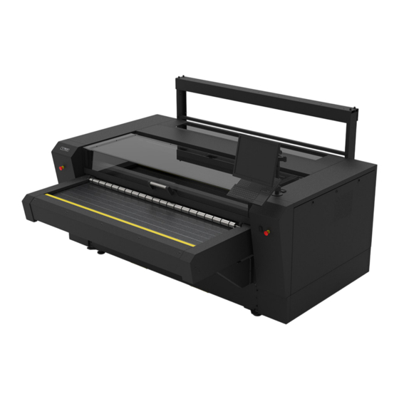
L1810 Gen 2.6 User’s Manual Laser Cutter 2.1.1 Front view Power on/off buttons (p. 16) Emergency stop button (p. 11) Safety cover lid (p. 16) Pressure roller (p. 19) Conveyor system (p. 17) with fume extraction/vacuum chambers underneath (p. 17) Finger safety plates (p.16) -
Page 15: Rear View
L1810 Gen 2.6 User’s Manual 2.1.2 Rear view Feed button (p. 19) Emergency stop button (p. 11) Unwinder connection End Of Roll signal cable Main power switch (p. 16) Ethernet connection (p. 16) Unwinder power connection Air pressure regulator (p. 63) Pressure roller (p. -
Page 16: Main Power Switch
L1810 Gen 2.6 User’s Manual 2.1.3 Main power switch WARNING: Pressing the OFF button will not cut all the power in the machine! Before opening any covers to perform service or maintenance, always switch off power using the main power switch. -
Page 17: Conveyor System
L1810 Gen 2.6 User’s Manual 2.1.9 Conveyor system The conveyor system, equipped with honeycomb or blade conveyor planks, transports the material through the working area and then out of the machine. The material is held down by the vacuum/extraction system underneath the conveyor bed, resulting in a clean cut and precise material transport. -
Page 18: Cutting Head Nozzle
L1810 Gen 2.6 User’s Manual 2.1.11 Cutting head nozzle The cutting head nozzle emits the laser beam that cuts the material in the cutting area. Nozzle height To have a clean cut a good focus of the laser beam is required. As a rule of thumb, we set the nozzle 4mm above the material. -
Page 19: Head Camera
L1810 Gen 2.6 User’s Manual 2.1.12 Head camera The laser cutter is always equipped with a head camera. The head camera supports the following advanced work methods: • Cut-to-Frame (also known as Fixed Size cutting) • Barcode workflow (requires Pro Pack). -
Page 20: Unwinder (Optional)
L1810 Gen 2.6 User’s Manual Unwinder (optional) A motorised unwinder eliminates fabric distortion while cutting by securing a constant and stable fabric feed onto the cutting bed. As the roll unwinds, a loop is created to relax the material, reducing distortion, and secure an accurate cut. -
Page 21: Fume Extraction And Vacuum System
L1810 Gen 2.6 User’s Manual Fume extraction and vacuum system WARNING: Before commencing any cutting procedure, ensure that the fume extraction system is in good working order and operates correctly. Some material may produce hazardous fumes if cut using the laser – check with the material supplier or manufacturer before cutting. -
Page 22: Water Chiller (Optional)
Water chiller (optional) NOTE: The information in this chapter only applies to the water chiller supplied by Summa. If another water chiller is used, this information is not applicable, and you should refer to the supplier's documentation of your water chiller. -
Page 23: Temperature
L1810 Gen 2.6 User’s Manual 2.4.2 Temperature The thermostat controller uses a setpoint which is the target temperature, i.e., the water temperature that is maintained in the reservoir. When the laser cutter is in operation and the cooler reservoir temperature reaches the setpoint + 2°C, the water chiller starts operating and cools the reservoir down until the temperature setpoint - 2°C is reached, after which it stops... -
Page 24: Starting Up The Laser Cutter
L1810 Gen 2.6 User’s Manual STARTING UP THE LASER CUTTER Check whether maintenance tasks need to be performed. For more information, refer to chapter 4.5 Maintenance Overview on page 74. Switch on the power supply to the laser cutter. Power on the laser cutter. -
Page 25: Set Working Area
L1810 Gen 2.6 User’s Manual Set working area Click on the Set working area icon to set the origin and size. Use the arrows, fill in the values or click in the area to set the origin. Use the camera or the laser pointer as guide for the position of the origin or media size (click on the icon on the right side between those two). -
Page 26: Info
L1810 Gen 2.6 User’s Manual Info The first info field displays the info on the type of laser cutter and the revision. The second info field displays the type of laser. If the fields are not filled in, then click on refresh info. -
Page 27: Maintenance
L1810 Gen 2.6 User’s Manual MAINTENANCE This chapter explains all maintenance works that need to be performed on the laser cutting system. A complete overview can be found in chapter 4.5 Maintenance Overview on page 74. WARNING: Before performing any maintenance, disconnect the laser cutter from the main power supply. -
Page 28: Laser Beam Alignment
It is ALWAYS, also including during this calibration process, prohibited to adapt, disable or override the safety systems of the machine. When the machine is misused or when the safety systems are not functioning as defined by the manufacturer, Summa cannot be held accountable for any mechanical damage or injuries caused. -
Page 29: Preparation
L1810 Gen 2.6 User’s Manual Preparation 4.1.1.2.1 Covers Open the polycarbonate lid. Remove the two screws on the bottom of the front hinge cover and open the cover. Use the universal cross key to unlock (do not remove) the left panel. -
Page 30: Spot Mode
It will be frequently used throughout the calibration process. Use the program GoCare to do this. Start the program Summa GoCare. If the model and laser type are not showing, then click on the icon refresh info. Only when this is shown is it certain that the program can control the laser cutter. -
Page 31: Laser Alignment
L1810 Gen 2.6 User’s Manual Laser alignment The purpose of this adjustment is to get the laser beam to hit the material properly at any position. Poorly aligned lasers can cause a less powerful output at the nozzle, damage, or harm to the operator due to unpredictable reflections. -
Page 32: Check Corners
L1810 Gen 2.6 User’s Manual 4.1.1.3.2 Check corners Start by checking if the laser hits the target in the centre in all four corners of the working area. Put the target holder with a target in the cutting head opening. - Page 33 The actual results can vary due to mechanical tolerances. CASE 1: There are no marks on the targets. Contact your Summa dealer for further technical support. CASE 2: There is only a mark on target 1. Continue to chapter 4.1.1.3.3.1 Check beam path on page 37.
- Page 34 CASE 4: The marks on targets 1, 2, and 3 are in the same place but not centred. This means that the laser module or primary mirror slide probably moved. Contact your Summa dealer for further technical support. CASE 5: The marks on targets 1 and 2 are in the same place, while the marks on targets 3 and 4 are lower or higher than that.
- Page 35 L1810 Gen 2.6 User’s Manual CASE 6: The marks on targets 1 and 2 are centred, but the marks on targets 3 and 4 do not meet the specifications. Follow the procedure from chapter 4.1.1.3.4.2 Laser parallel with top beam axis on page 44 and use the specifications below.
-
Page 36: Primary Mirror Calibration
L1810 Gen 2.6 User’s Manual 4.1.1.3.3 Primary mirror calibration The primary mirror is the first component that reflects the laser beam. It is in front of the laser unit. The primary mirror changes the angle (not the height!) of the laser beam. The angle can be adjusted by means of the thumbscrews on the mirror holder ( ... - Page 37 L1810 Gen 2.6 User’s Manual 4.1.1.3.3.1 Check beam path This calibration ensures that the laser hits the secondary mirror on the far left and right of the machine. (Re)place a target in the cutting head. Use spot mode to move the head all the way to the front left side and fire the laser.
- Page 38 L1810 Gen 2.6 User’s Manual Unscrew the locknuts and bolt to adjust the thumbscrews on the primary mirror to shoot as close as possible to the previous mark. : Up and down : Left and right Resecure the locknuts ...
- Page 39 L1810 Gen 2.6 User’s Manual 4.1.1.3.3.2 Laser beam parallel with front axis The purpose of this calibration is to align the laser parallel to the front axis. This ensures that the laser beam always hits the secondary mirror at the same spot, regardless of where it is positioned along the front axis.
- Page 40 L1810 Gen 2.6 User’s Manual Open the left side cover. Unscrew the locknuts and bolt to adjust the primary mirror so that the second mark is exactly on top of the previous mark. : Up and down ...
-
Page 41: Secondary Mirror
L1810 Gen 2.6 User’s Manual 4.1.1.3.4 Secondary mirror The secondary mirror is mounted on the top beam. It moves along with the top beam and reflects the laser beam to the cutting head. Adjusting the mirror holder can be done by means of the thumbscrews ( ... - Page 42 L1810 Gen 2.6 User’s Manual 4.1.1.3.4.1 Check beam path This calibration ensures that the laser hits the (45º angled) third mirror in the cutting head when it is positioned in the front and back of the top beam. Put the target holder with a target in the cutting head opening.
- Page 43 L1810 Gen 2.6 User’s Manual Fire the laser. Unscrew the locknuts and bolt to adjust the secondary mirror to shoot as close as possible to first mark. : Up and down : Left and right Return to step 4.
- Page 44 L1810 Gen 2.6 User’s Manual 4.1.1.3.4.2 Laser parallel with top beam axis Like the previous calibration, this will align the laser parallel to the top beam axis. This ensures that the laser beam always hits the (45º angled) third mirror at the same spot, regardless of where it is positioned along the top beam axis.
- Page 45 L1810 Gen 2.6 User’s Manual Move the head all the way to the back and fire the laser. Marks are on top of each other Marks NOT on top of each other Continue to chapter 4.1.1.3.5 Third (45º Continue to step 4.
-
Page 46: Third (45º Angled) Mirror
L1810 Gen 2.6 User’s Manual 4.1.1.3.5 Third (45º angled) mirror This is the last mirror in the beam path and guides the laser beam through the centre opening of the nozzle. Maintenance... - Page 47 L1810 Gen 2.6 User’s Manual 4.1.1.3.5.1 Centring laser beam through nozzle Use the thumbscrew to raise the nozzle as high as possible. Mount the nozzle target holder on the bottom of the nozzle. (Re)place the target. Maintenance...
- Page 48 L1810 Gen 2.6 User’s Manual Use spot mode to fire the laser. Mark perfectly centred on target Mark NOT centred on target Continue to chapter 4.1.1.3.6 Final corners Continue to step 5. check on page 49. Use the hex screws to centre the mark on the target.
-
Page 49: Final Corners Check
L1810 Gen 2.6 User’s Manual 4.1.1.3.6 Final corners check After the above calibrations have been performed, the laser beam should hit the target as specified below. Put the target holder with a target in the cutting head opening. Use spot mode to fire the laser in the order pictured below. - Page 50 L1810 Gen 2.6 User’s Manual The results should match the specifications below. Target No Position Result Front left Mark centred on target Front right Mark centred on target Back right Mark centred on target Back left Mark centred on target...
-
Page 51: Optical Components
L1810 Gen 2.6 User’s Manual 4.1.2 Optical components To achieve maximal power output from the laser cutter, the system’s optical components must be in good working order. Poorly cleaned optics absorb more heat and are more likely to burn or shatter! Laser unit ... -
Page 52: Cleaning The Primary Mirror
L1810 Gen 2.6 User’s Manual Cleaning the primary mirror Remove the left-hand side cover of the laser cutter using a control cabinet key to gain access to the primary mirror. It is important to touch the mirror as little as possible. Use the air blower to remove any debris from the mirror while the mirror remains in its position. - Page 53 L1810 Gen 2.6 User’s Manual If this still does not remove all the debris, only then apply a small amount of IPA optical cleaning solution onto the cleaning cloth provided in the tool kit and clean the mirror while the mirror remains in its position. Do not adjust the mirror position and do not apply too much pressure to the mirror;...
-
Page 54: Cleaning The Secondary Mirror
L1810 Gen 2.6 User’s Manual Cleaning the secondary mirror 1. Open the safety cover lid. 2. Remove the four bottom screws of the front guard and open it. 3. Apply a small amount of IPA optical cleaning solution onto the cleaning cloth provided in the tool kit and clean the mirror while in position. -
Page 55: (Un)Installing The Static And Travelling Mirrors
L1810 Gen 2.6 User’s Manual (Un)Installing the static and travelling mirrors For removing the static and travelling mirrors from their mount (e.g., in the event of a defect) and installing them again, use the spanner wrench (delivered in the toolbox). -
Page 56: Cleaning The Cutting Head Lens
L1810 Gen 2.6 User’s Manual Cleaning the cutting head lens The cutting head lens coating is fragile; do not drop the lens onto any hard surface or touch the lens with any sharp objects as this may damage the lens and reduce cutting efficiency. - Page 57 L1810 Gen 2.6 User’s Manual Remove the lens ring by turning it counterclockwise. Carefully drop the lens onto a clean microfibre cloth. WARNING: Ensure that the area is sufficiently ventilated. The solvent should be kept away from heat or flames. Wear appropriate clothing and safety goggles.
- Page 58 L1810 Gen 2.6 User’s Manual This is a good time to also clean the nozzle. For more information, refer to chapter 4.1.3.1 Nozzle cleaning on page 62. Hold the edges of the lens with the surface curved outwards facing upward and carefully place it into the nozzle barrel.
-
Page 59: Cleaning The Cutting Head Mirror
L1810 Gen 2.6 User’s Manual Cleaning the cutting head mirror Remove the cutting head by releasing the M4 screw and detaching the pneumatic tube. Release (do not remove) the mirror securing screw holding the mirror securing clip. Rotate the clip to release the mirror. - Page 60 L1810 Gen 2.6 User’s Manual Gently rotate the head so that the mirror falls out onto a microfibre cleaning cloth. Apply IPA optical cleaning solution to the mirror face and let it soak for a few seconds. Gently lay an optical cleaning solution cloth on one edge of the mirror and gently draw the cloth right across the mirror in one continuous movement.
-
Page 61: Cleaning The Vision Camera Lenses
L1810 Gen 2.6 User’s Manual Cleaning the Vision camera lenses The lenses of the Vision cameras in the gantry are accessible at any time; they are not covered. Use the air blower and/or soft brush to dust the lenses. Maintenance... -
Page 62: Pneumatics
L1810 Gen 2.6 User’s Manual 4.1.3 Pneumatics Nozzle cleaning To ensure proper airflow while cutting, the nozzle needs to be free of dirt. This step is preferably done with the barrel disassembled and the lens removed. Remove the cutting head by releasing the M4 screw and detaching the pneumatic tube. -
Page 63: Airflow
L1810 Gen 2.6 User’s Manual Airflow Depending on the type of material being processed, an appropriate airflow must be present. Find the pressure regulator at the back of the machine. Check if all pneumatics tubes are still connected properly. Check the pressure gauge to see if it is set properly: range between 0.5 bar (7.2psi) and 3 bar (43.51psi). -
Page 64: Axes
L1810 Gen 2.6 User’s Manual 4.1.4 Axes Axis movement Check smooth movement on both axes. Use the arrow keys at the Set working area action in GoProduce Laser edition to move the cutting head to each corner of the cutting bed and check for any irregularities. -
Page 65: Air Filters
L1810 Gen 2.6 User’s Manual 4.1.5 Air filters To protect the internal components from surrounding dust particles, three filters are fitted around the machine. Open the left and the right cover using the control cabinet key. Remove the filter from the left/right cover and the back panel. -
Page 66: Conveyor Planks
L1810 Gen 2.6 User’s Manual 4.1.6 Conveyor planks To ensure proper fume extraction and vacuum for material transportation, the conveyor planks need to be free of dust and lint. Open the safety cover lid and visually inspect the conveyor planks for cleanness and damage. -
Page 67: Air-Cooled Laser
L1810 Gen 2.6 User’s Manual Air-cooled laser This section is only applicable if an air-cooled laser unit is installed inside the laser cutter. Check the serial number label on the back right of the machine. An air-cooled laser cutting machine type ends with /50 or /100. -
Page 68: Water-Cooled Laser
L1810 Gen 2.6 User’s Manual Water-cooled laser This section is only applicable if a water-cooled laser unit is installed inside the laser cutter. Check the serial number label on the back right of the machine. A water-cooled laser cutting machine type ends with /120 or /250. -
Page 69: Chiller
L1810 Gen 2.6 User’s Manual 4.3.2 Chiller The laser unit is cooled with deionised water, to avoid bacterial infestation. Water level The chiller needs a controlled water level to deliver full cooling capacity. 1. Check the water level through the inspection glass. The water level should be at least halfway. -
Page 70: Water Quality
L1810 Gen 2.6 User’s Manual Water quality Over time, the chiller water can become cloudy. Cloudy chiller water is no longer good for use. Replace with deionised water only. Remove the reservoir cap. Open the valve at the bottom of the chiller to drain all the chiller water. -
Page 71: Water Pipes
L1810 Gen 2.6 User’s Manual Water pipes To ensure proper water flow, the water hoses need to be in good condition and without kinks or sharp bends. Close the IN and OUT valves on the chiller. Drain the water from the damaged water hose. -
Page 72: Chiller Air Filter
L1810 Gen 2.6 User’s Manual Refit the water hose into the chiller and open both valves completely. Chiller air filter To ensure proper airflow through the chiller, the grid and the air filter need to be free of dust. The filter can be easily removed by hand. -
Page 73: Extraction Systems
L1810 Gen 2.6 User’s Manual Extraction systems To ensure proper fume extraction and vacuum in the cutting area, the extraction hoses need free of dust and debris. Remove the vacuum hose from the extraction system (extraction fan, BOFA, or own system). -
Page 74: Maintenance Overview
L1810 Gen 2.6 User’s Manual Maintenance Overview ATTENTION: Make sure the power supply to the laser cutter is switched off before starting maintenance tasks! ATTENTION: The intervals below are the maximum allowed time between maintenance tasks: • 8 hours or one day* •... - Page 75 L1810 Gen 2.6 User’s Manual LASER CUTTER Component Task Max. Interval* Reference Vision camera lens Clean/Check and scanning camera Dealer 1 Year calibration UV filter Clean and All Rails Dealer 1 Year Lubricate X-Belt Tension Check/Adjust Dealer 1 Year Y-Belts Tension...
-
Page 76: Included Accessories
L1810 Gen 2.6 User’s Manual INCLUDED ACCESSORIES The following accessories are included with the purchase of your L1810 Gen2.6 laser cutter: • Conveyor system (excl. planks) • Front extension • Head camera • Pressure rollers • Summa GoProduce Laser Edition (excl. computer) •... -
Page 77: Troubleshooting
L1810 Gen 2.6 User’s Manual TROUBLESHOOTING The laser is not cutting well in all areas of the bed: • The focus height is incorrect. • The lens is upside down. • The optical components are in a poor state of cleanliness. -
Page 78: Error Messages
L1810 Gen 2.6 User’s Manual Error Messages Error messages will be shown in the monitor section of the device tab in the program GoProduce Laser edition (so make sure it is always running). An example of a warning is shown in the figure below. - Page 79 L1810 Gen 2.6 User’s Manual Error Possible Checks Corrective Action Message Cause Material Check affected area for any Object loose material, objects or thread Remove any debris from obstructing that have become moving parts movement entangled in moving parts Rail Dirty...
-
Page 80: Gocare
L1810 Gen 2.6 User’s Manual GOCARE The GoCare software allows upgrading the laser cutter firmware, making device and Vision camera backups, and restoring machine settings. The user manual of GoCare is available for download on our website (www.summa.com/en/support/user-manuals/). GoCare... -
Page 81: Goproduce Laser Edition
User’s Manual GOPRODUCE LASER EDITION Summa GoProduce Laser Edition is a Windows-based production software that integrates the L-Series into the workflow. It is the perfect link between the design station, RIP station, printers and cutting devices. Once the workflow is set up, macros automate the process.
Need help?
Do you have a question about the L1810 and is the answer not in the manual?
Questions and answers