Advertisement
Table of Contents
- 1 Table of Contents
- 2 Section 1 Getting Started
- 3 Section 2 Installation
- 4 Section 3 Temperature Control Operation
- 5 Section 4 System Operation
- 6 Section 5 Diagnostics
- 7 Section 6 Maintenance
- 8 Section 7 Troubleshooting
- 9 Section 8 Specifications
- 10 Appendix A CMX Closed Loop to Open Loop Cooling Conversion
- 11 Appendix B CMX Open Loop to Closed Loop Cooling Conversion
- 12 Appendix C CMX 2104 Controller Information
- Download this manual
Advertisement
Table of Contents

Related Manuals for Chromalox MicroTherm CMX Series


Summary of Contents for Chromalox MicroTherm CMX Series
- Page 1 Thermal Devices, Inc. Mount Airy, Maryland USA www.thermaldevices.com Installation & Operation Manual Circulating Water Temperature Control System PQ450 161-123417-036 March 2019 Thermal Devices, Inc. Mount Airy, Maryland USA www.thermaldevices.com...
-
Page 2: Table Of Contents
Thermal Devices, Inc. Mount Airy, Maryland USA www.thermaldevices.com Table of Contents Contents Page Number Section 1 Getting Started ............................1 Section 2 Installation .............................. 4 Section 3 Temperature Control Operation ......................9 Section 4 System Operation ..........................10 Section 5 Diagnostics ............................11 Section 6 Maintenance ............................ -
Page 3: Section 1 Getting Started
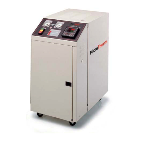
Introduction Electrical and hydraulic components are located in Congratulations on purchasing the Chromalox CMX distinctly separate areas in the system to better man- Series microTHERM™ Temperature Control System. age heat buildup and prevent component damage. - Page 4 Thermal Devices, Inc. Mount Airy, Maryland USA www.thermaldevices.com Figure 1.1 System Photo (Side View) High watt density, INCOLOY ® sheath Chromalox ® heating elements. Operating temperatures of 50° to 250°F ASME pressure relief valve opens if sys- for a wide variety of applications.
- Page 5 Figure 1.2 Control Panel Dual pressure gauges simplify monitoring of both to process and from process pressures. Chromalox’s Temperature and Process Controller features separate PID algorithms for heat and cool control modes, dual display of setpoint and process temperatures, and simple configuration parameters with alphanumeric cues.
-
Page 6: Section 2 Installation
Thermal Devices, Inc. Mount Airy, Maryland USA www.thermaldevices.com Section 2 – Installation Before Open-Loop Hydraulic Installation: Hydraulic Installation, Open Loop: Before proceeding with the installation of the open- 1. Locate the unit as close as possible to the con- loop system, please take note of the following impor- trolled process in order to minimize pressure tant information: drops. - Page 7 Thermal Devices, Inc. Mount Airy, Maryland USA www.thermaldevices.com Figure 2.1 Open-Loop Cooling Piping Connections ® Chromalox 1-7/8” DRAIN/ COOLING OUTLET 6" FROM PROCESS TO PROCESS 28-1/2” 12-5/16” WATER SUPPLY/ COOLING INLET 6" 7" 4" 15" Rear View Note: Dimensions are nominal ± 3/8”...
- Page 8 Thermal Devices, Inc. Mount Airy, Maryland USA www.thermaldevices.com Before Closed-Loop Hydraulic Installation Before proceeding with the installation of the Closed- 4. Connect the cooling water supply (30 psi to 80 psi) loop system, please take note of the following informa- to the unit’s 1/2”...
- Page 9 Thermal Devices, Inc. Mount Airy, Maryland USA www.thermaldevices.com Figure 2.1 Open-Loop Cooling Piping Connections ® Chromalox COOLING OUTLET 1-7/8” WATER SUPPLY/ COOLING INLET 6" FROM PROCESS TO PROCESS S” and “TO PR 28-1/2” 12-5/16” 6" 7" 4" 15" Rear View Note: Dimensions are nominal ±...
- Page 10 Thermal Devices, Inc. Mount Airy, Maryland USA www.thermaldevices.com Electrical Installation 4. Pump Rotation Check: With power off, check the wiring connections by tugging on the lines. Tighten HAZARD OF ELECTRIC SHOCK. The heat trans- all terminals in the control area. These can loosen fer system must be grounded using grounding due to vibration in shipping.
-
Page 11: Section 3 Temperature Control Operation
Most CMX units shipped from 1995 through 2018 will Below is a list of the most common controller setups, have been equipped with a Chromalox model 2104 with additional details available in Appendix C temperature controller. For these units, please refer- CMX-250, Contactor –... -
Page 12: Section 4 System Operation
Thermal Devices, Inc. Mount Airy, Maryland USA www.thermaldevices.com Section 4 – Operation down to prevent release of hot fluid. Note: This is a PID type controller and cycling of the On both open Closed-loop systems, turn on wa- heat and cool can be expected below and above set- ter and insure the water supply lines are free point. -
Page 13: Section 5 Diagnostics
Thermal Devices, Inc. Mount Airy, Maryland USA www.thermaldevices.com Section 5 – Diagnostics HAZARD OF ELECTRIC SHOCK. Disconnect system power, if the Pump Overload Indicator is illuminated. Hazard of electric shock or elec- trocution. Disconnect all power and piping to the system. After the system power is disconnected, solve the electrical current problem. -
Page 14: Section 6 Maintenance
Thermal Devices, Inc. Mount Airy, Maryland USA www.thermaldevices.com Section 6 – Maintenance Draining Drain the unit before taking it out of service for a pe- ELECTRIC SHOCK AND BURN HAZARD. Discon- riod of time, or if it is exposed to freezing temperatures nect all power before servicing or performing while out of service. - Page 15 Thermal Devices, Inc. Mount Airy, Maryland USA www.thermaldevices.com Heater Removal/Replacement 7. Remove cable from the heater. 8. Unbolt the heater (4 bolts) and remove. HAZARD OF ELECTRIC SHOCK. Disconnect all power and piping to system. 9. Remove Bussing from old heater and re-install on replacement heater, using the same orientation.
- Page 16 Thermal Devices, Inc. Mount Airy, Maryland USA www.thermaldevices.com Pump Removal/Replacement Heat Exchanger Removal/Replacement (Closed loop system) 1. Disconnect all power to the system. 2. Bleed pressure and drain all water from the system. HAZARD OF ELECTRIC SHOCK. Disconnect all power and piping to system. 3.
- Page 17 Transformer 240/480V 315-303786-001 Caster (4 total) 375-123425-003 Control Voltage Fuse 128-123445-005 Heater Contactor See table above These parts may vary for non-catalog items. Please consult your local Chromalox representative. (800-443-2640 or www.chromalox.com) Thermal Devices, Inc. Mount Airy, Maryland USA www.thermaldevices.com...
- Page 18 Thermal Devices, Inc. Mount Airy, Maryland USA www.thermaldevices.com Figure 6.6 Replacement Parts Identification From Process To Process CMX Series Temperature Control System Chromalox ® HEAT Pump COOL System Diagnostics OUT3 START Low Water Pressure OUT4 Pump Overload RESET STOP PAGE...
-
Page 19: Section 7 Troubleshooting
Refer to 2104 Controller Techni- cal manual, page 35, for further information. If you continue to have problems with the system after review of the above issues, please contact Chromalox Product Service at 800-443-2640. Thermal Devices, Inc. Mount Airy, Maryland USA www.thermaldevices.com... -
Page 20: Section 8 Specifications
Thermal Devices, Inc. Mount Airy, Maryland USA www.thermaldevices.com Section 8 – Specifications Standard 3/4 HP Pump Heating Process Approximate Pump Nominal Capacity Standard Connection Drain/Supply Dimensions Size (HP) Flow (gpm) (kW) Voltages dia. (Inches) dia. (Inches) (Inches) 240 or 480 1-1/4 NPT 1/4 NPT 29 height... -
Page 21: Appendix A Cmx Closed Loop To Open Loop Cooling Conversion
Note: All warnings and cautions denoted This sheet details the steps taken and material required throughout this user’s manual also apply to the to convert a Chromalox CMX microTHERM hot water modifications listed below. General instruc- system from closed loop cooling to open loop cool- tions and specifications referring to the open... -
Page 22: Appendix B Cmx Open Loop To Closed Loop Cooling Conversion
Note: All warnings and cautions denoted This sheet details the steps taken and material required throughout this user’s manual also apply to the to convert a Chromalox CMX microTHERM hot water modifications listed below. General instruc- system from open loop cooling to closed loop cooling. - Page 23 Thermal Devices, Inc. Mount Airy, Maryland USA www.thermaldevices.com DRAIN / COOLING OUTLET FROM Fig. 2 PROCESS PROCESS WATER SUPPLY COOLING INLET OPEN LOOP OPEN LOOP Figure B3 - Open Loop Cooling COOLING OUTLET WATER SUPPLY COOLING INLET Fig. 1 FROM PROCESS PROCESS CLOSED LOOP...
- Page 24 Thermal Devices, Inc. Mount Airy, Maryland USA www.thermaldevices.com Installation Steps 1. Drain fluid from system and disconnect all power. 8. Fig. 1: Install 3/8” copper tubing (47) in compres- sion fitting (46). Route tubing to compression fitting 2. Fig. 2: Remove 1/4” NPT elbow (39), nipple (15) (46) near pump inlet shown in Fig.
-
Page 25: Appendix C Cmx 2104 Controller Information
Thermal Devices, Inc. Mount Airy, Maryland USA www.thermaldevices.com Appendix C CMX-250, Heat Only 4081 Controller Configuration Menu Output Configuration Lock Code Output 1 Usage Unused Input Configuration Input 1 setup Output 2 Usage Primary Input Type J Thermocouple Output 3 Usage OR alarm-events reverse Engineering Units ˚F... - Page 26 Thermal Devices, Inc. Mount Airy, Maryland USA www.thermaldevices.com CMX-275, High Temperature 4081 Controller, Heat Only Configuration Menu Output Configuration Lock Code Output 1 Usage Unused Input Configuration Input 1 setup Output 2 Usage Primary Input Type J Thermocouple Output 3 Usage OR alarm-events reverse Engineering Units ˚F...
- Page 27 Thermal Devices, Inc. Mount Airy, Maryland USA www.thermaldevices.com CMX-275, High Temperature 4081 Controller with SCR Configuration Menu Output Configuration Lock Code Output 1 Usage Primary Input Configuration Input 1 setup Output 2 Usage Unused Input Type J Thermocouple Output 3 Usage OR alarm-events reverse Engineering Units ˚F...
- Page 28 Thermal Devices, Inc. Mount Airy, Maryland USA www.thermaldevices.com CMX-275, High Temperature 4081 Controller Configuration Menu Output Configuration Lock Code Output 1 Usage Unused Input Configuration Input 1 setup Output 2 Usage Primary Input Type J Thermocouple Output 3 Usage OR alarm-events reverse Engineering Units ˚F OPR3 OR selection...
- Page 29 Thermal Devices, Inc. Mount Airy, Maryland USA www.thermaldevices.com CMX-250 STD Heat/Cool 4081/4082 Controller with SCR Configuration Menu Output Configuration Lock Code Output 1 Usage Primary Input Configuration Input 1 setup Output 2 Usage Unused Input Type J Thermocouple Output 3 Usage OR alarm-events reverse Engineering Units ˚F...
- Page 30 Local Set point Alternate Set Point Source Not Used Main Set Point 250˚F Limited Warranty: Please refer to the Chromalox limited warranty applicable to this product at http://www.chromalox.com/customer-service/policies/termsofsale.aspx. Chromalox, Inc. 2150 N. Rulon White Blvd., Ogden, UT 84404 Phone: 1-800-368-2493 www.chromalox.com...
Need help?
Do you have a question about the MicroTherm CMX Series and is the answer not in the manual?
Questions and answers