
Related Manuals for Hospira PLUMA+3 12348-04


Summary of Contents for Hospira PLUMA+3 12348-04
- Page 1 INFUSION SYSTEM For use with list numbers 12348-04 and 12618-04 Technical Service Manual 430-95424-002 (Rev. 01/06)
- Page 2 Hospira retains all the exclusive rights of dissemination, reproduction, manufacture, and sale. Any party using this document accepts it in confidence, and agrees not to duplicate it in whole or in part nor disclose it to others without the written consent of Hospira. ®...
- Page 3 (Rev. 09/03) 430-95424-002 Second Issue (Rev. 01/06) Updated Section 1, Section 5, Section 6, and Section 8 Updated battery information Incorporated Hospira name change and updated to current style Updated graphics throughout Updated back page Technical Service Manual 430-95424-002 (Rev. 01/06)
- Page 4 CHANGE HISTORY This page intentionally left blank. ® 430-95424-002 (Rev. 01/06) Plum A+ 3 Infusion System...
- Page 5 Contents Section 1 INTRODUCTION ......1.1 SCOPE ......1.2 CONVENTIONS .
- Page 6 CONTENTS 4.2.2 POWER SUPPLY SUBSYSTEM ....4-13 4.2.2.1 MAIN SWITCHING REGULATOR ... 4-13 4.2.2.2 MAIN REGULATOR FAULT DETECTION .
- Page 7 CONTENTS 5.2.12 PROXIMAL AIR-IN-LINE TEST ....5.2.13 DISTAL AIR-IN-LINE TEST ....5-10 5.2.14 DISTAL OCCLUSION TEST .
-
Page 8: Table Of Contents
CONTENTS 7.2.14.2 KEYPAD REPLACEMENT....7-30 7.2.14.3 DISPLAY ASSEMBLY REPLACEMENT ..7-31 7.2.14.4 CPU/DRIVER CABLE REPLACEMENT ..7-32 7.2.14.5 MOTOR POWER CABLE REPLACEMENT . - Page 9 CONTENTS Figure 7-11. Main Chassis Components (1 of 2) ....7-28 Figure 7-11. Main Chassis Components (2 of 2) ....7-29 Figure 7-12.
- Page 10 CONTENTS This page intentionally left blank. ® 430-95424-002 (Rev. 01/06) viii Plum A+ 3 Infusion System...
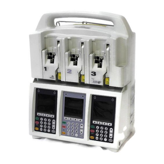
- Page 11 Section 1 INTRODUCTION ® The Hospira Plum A+ 3 infusion system is designed to meet the growing demand for hospital wide device standardization. The system consists of three component infusers, which are designated line 1, line 2, and line 3. By incorporating three lines into one unit, ®...
-
Page 12: Table 1-1. Conventions
SECTION 1 INTRODUCTION CONVENTIONS The conventions listed in Table 1-1 are used throughout this manual. Table 1-1. Conventions Convention Application Example Italic Reference to a section, figure, (see Section 6.1) table, or publication [ALL CAPS] In-text references to keys [START] and touchswitches ALL CAPS Screen displays... - Page 13 1.4 ACRONYMS AND ABBREVIATIONS ACRONYMS AND ABBREVIATIONS Acronyms and abbreviations used in this manual are as follows: A Ampere AC Alternating current A/D Analog-to-digital ADC Analog-to-digital converter APP Air, pressure, and pin BCR Barcode reader CCA Clinical care area CCFT Cold cathode fluorescent tube CMOS Complementary metal-oxide semiconductor CPU Central processing unit DAC Digital-to-analog converter...
- Page 14 SECTION 1 INTRODUCTION LCD Liquid crystal display LED Light emitting diode L/S Line select MB Megabyte MHz Megahertz min Minute mL Milliliter mL/hr Milliliter per hour MMIO Memory-mapped input/output MOSFET Metal-oxide semiconductor field-effect transistor ms Millisecond nF nanofarad Op-amp Operational amplifier pF picofarad PROM Programmable read-only memory PVT Performance verification test...
- Page 15 IEC 60601-1-1. If in doubt, contact Hospira Technical Support Operations (see Section 6.1). The instrument installation procedure consists of unpacking, inspection, and self test.
- Page 16 CAUTION: Inspect the infuser for evidence of damage. Do not use the device if it appears to be damaged. Should damage be found, contact Hospira (see Section 6.1). Inspect the infusion system periodically for signs of defects such as worn accessories, broken connections, or damaged cable assemblies.
-
Page 17: Figure 1-1. Display And Keypad
“CASSETTE TEST IN PROGRESS” message. 7. The “CLEAR SETTINGS?” message may appear. Press the [YES] softkey. 8. Press [ON/OFF] to turn off the infuser. LINE FLOW INDICATORS HOSPIRA Plum A+ Version X.XX MM/DD/YY STATUS Copyright Hospira Inc. REGION... - Page 18 SECTION 1 INTRODUCTION BIOMED SETTINGS The biomed settings screens contain the following options that can be changed or reviewed by qualified personnel: - IV screen parameters - Alarms log - Set time and date All infusers (new or refurbished) are shipped with factory settings (see Table 1-2).
-
Page 19: Table 1-2. System Configuration Data
1.8 BIOMED SETTINGS Table 1-2. System Configuration Data Data Options Range Factory Setting Maximum macro IV mode delivery rate 0.1 - 99.9 mL/hr and 999 mL/hr 100 - 999 mL/hr Macro distal occlusion alarm 1 to 15 psi 6 psi (pressure level) Deliver together enable Concurrent or Piggyback... -
Page 20: Figure 1-3. Iv Parameters
SECTION 1 INTRODUCTION 1.8.1 IV PARAMETERS The IV parameters screen contains common IV parameters and macro IV parameters (see Figure 1-3). To change the IV parameters, see Figure 1-6 Figure 1-7, then proceed as follows: 1. Access the biomed settings screen as described in Section 1.8. -
Page 21: Figure 1-4. Alarms Log
1.8 BIOMED SETTINGS 1.8.2 ALARMS LOG Note: The alarms log will retain the latest 40 alarm and malfunction codes, listed in order from the most current to the oldest. To view the alarms log, see Figure 1-2 Figure 1-4, then proceed as follows: 1. -
Page 22: Figure 1-5. Setting The Time And Date
SECTION 1 INTRODUCTION 1.8.3 SETTING THE TIME AND DATE Note: The infusion system will automatically display February 29 on leap years. Note: Daylight savings and time zone changes must be made manually. To set the time and date, see Figure 1-5, then proceed as follows: 1. -
Page 23: Figure 1-6. Common Iv Parameters
1.8 BIOMED SETTINGS BIOMED SETTINGS Common IV Parameters Continue Rate Deliver Together Concurrent Enable Delay/Standby Callback Default Select using Change Value Change Enter Cancel/ Value Back 02K03004 Figure 1-6. Common IV Parameters BIOMED SETTINGS Macro IV Parameters Default Distal Press Max Rate 999 mL/hr Enter Value using keypad... - Page 24 SECTION 1 INTRODUCTION This page intentionally left blank. ® 430-95424-002 (Rev. 01/06) 1 - 14 Plum A+ 3 Infusion System...
- Page 25 (whether such cause be based in contract, negligence, strict liability, other tort, or otherwise) exceed the price of such product, and in no event shall Hospira be liable for incidental, consequential, or special damages or losses or for lost business, revenues, or profits.
- Page 26 SECTION 2 WARRANTY This page intentionally left blank. ® 430-95424-002 (Rev. 01/06) 2 - 2 Plum A+ 3 Infusion System...
- Page 27 A copy of the system operating manual is included with every Plum A+ 3 infusion system. Insert a copy here for convenient reference. If a copy of the system operating manual is not available, contact Hospira Technical Support Operations (see Section 6.1). Technical Service Manual 3 - 1...
- Page 28 SECTION 3 SYSTEM OPERATING MANUAL This page intentionally left blank. ® 430-95424-002 (Rev. 01/06) 3 - 2 Plum A+ 3 Infusion System...
- Page 29 Section 4 THEORY OF OPERATION ® This section describes the Plum A+ 3 theory of operation. The theory of operation details the general description, electronic subsystem overview, printed wiring assemblies, remote mounted peripherals, and mechanical overview of the infusion system. Related drawings are provided in Section GENERAL DESCRIPTION...
-
Page 30: Figure 4-1. Electronic Functional Diagram
SECTION 4 THEORY OF OPERATION Alarms include the following: - Distal occlusion - Lockout violation - Proximal occlusion - VTBI complete - Proximal air-in-line - Valve/cassette test failure - Distal air-in-line - Nurse call - Low battery - No action alarm - Door open while pumping - Infuser idle for two minutes ELECTRONIC SUBSYSTEM OVERVIEW... - Page 31 4.2 ELECTRONIC SUBSYSTEM OVERVIEW 4.2.1 CPU SUBSYSTEM The CPU subsystem contains the main microcontroller, which is responsible for controlling the display/keyboard interface, external communications interfaces, barcode reader (BCR) interface, and system management. The CPU subsystem provides the following functions: - External memory devices access - LCD interfaces - Real-time clock generator interface - System watchdog...
- Page 32 SECTION 4 THEORY OF OPERATION 4.2.1.3 PROGRAMMABLE READ-ONLY MEMORY The CPU subsystem has two 512 K x 8 bit programmable read-only memory (PROM) memory devices, which provide a total of 1024 KB. The PROM space is expandable up to 2 MB. The PROM memory devices operate off the 3.3 V supply.
- Page 33 4.2 ELECTRONIC SUBSYSTEM OVERVIEW 4.2.1.7 LCD BACKLIGHT CONTROL The LCD panel is backlit by a cold cathode fluorescent tube (CCFT) lamp. The CCFT lamp requires 300 V to operate; a current controlled DC-to-AC voltage inverter circuit is used to deliver a current regulated sine wave to the lamp. A switching regulator regulates the CCFT current by monitoring feedback pin 3, and varies its output duty cycle to drive a DC/AC inverter.
- Page 34 SECTION 4 THEORY OF OPERATION 4.2.1.10 VOLTAGE MONITOR WATCHDOG TIMER It is important to protect the system during power transitions, and the CPU is reset after the V power supply is applied. The microprocessor supervisory circuit generates an automatic reset output during power up, power down, or brownout conditions. When the falls below the reset threshold voltage of 2.9 V , the reset signal (RESET*) goes low and holds the microprocessor in reset for approximately 200 ms after V...
-
Page 35: Figure 4-2. Serial Interface To Adc
4.2 ELECTRONIC SUBSYSTEM OVERVIEW I/O CLOCK SPCLK ADDRESS SPTXD DATA OUT SPRXD ANALOG INPUTS (OR INTERRUPT) REF+ 2.5V REF- GANA GDIG 98K01022 Figure 4-2. Serial Interface to ADC Table 4-1. Analog Inputs Signal Name Analog Input Address (hex) Description PRPRS Proximal pressure sensor DIPRS Distal pressure sensor... -
Page 36: Table 4-2. Keypad Map
SECTION 4 THEORY OF OPERATION 4.2.1.12 DIGITAL-TO-ANALOG CONVERTER The dual 8 bit digital-to-analog converter (DAC) generates two analog signals to control the phase A and phase B motor coil currents. The interface between the DAC device and the CPU is the 8 bit data bus, which is connected to DATA15:8. All the control signals for this DAC are generated by FPGA logic devices. - Page 37 4.2 ELECTRONIC SUBSYSTEM OVERVIEW 4.2.1.16 KEYPAD LOCKOUT INTERFACE A lockout switch (SW1) on the peripheral interface PWA locks the front panel keypad for all three infusers. A memory mapped input port (LOTSW*) reads the switch. The switch serves as a lockout request and software performs the lockout. 4.2.1.17 NURSE CALL INTERFACE A nurse call relay switch on the peripheral interface PWA indicates alarm conditions to...
-
Page 38: Table 4-3. Cpu-Power Supply Interface
SECTION 4 THEORY OF OPERATION 4.2.1.20 DATAPORT INTERFACE The CPU communicates with an external computer by way of a DataPort interface. The DataPort interface provides for remote monitoring of up to four infusers using a host computer with a modified RS-232-D serial interface. Infusers are either connected directly to the host or in a daisy chain configuration using junction boxes that provide a 5 bit hard ID via DIP switches on the junction box. -
Page 39: Table 4-4. Cpu-Mechanism Interface Signals
4.2 ELECTRONIC SUBSYSTEM OVERVIEW Table 4-3. CPU-Power Supply Interface Signal Name Type Description V12_0 12 V, low current supply for audio alarm OVRVLT* D, I Signal that indicates overvoltage, regulation problem on the power supply main regulator BACON D, I Buffered AC on signal IBATT A, I... - Page 40 SECTION 4 THEORY OF OPERATION Table 4-4. CPU-Mechanism Interface Signals Signal Name Type Description FLLS_B D, I Flag, L/S valve B pin detector FLPLRO D, I Flag, plunger rotation sensor FLPLTR D, I Flag, plunger translation sensor PXPRE Proximal pressure sensor enable PXPRS A, I Proximal pressure sensor...
- Page 41 4.2 ELECTRONIC SUBSYSTEM OVERVIEW 4.2.2 POWER SUPPLY SUBSYSTEM The power supply subsystem provides DC power to system circuits and interface software controlled power and battery management. The power supply subsystem provides for the following functions: - Main switching regulator - AC power detection - Main regulator fault detection - System power (secondary regulators) - Auxiliary supplies...
- Page 42 SECTION 4 THEORY OF OPERATION 4.2.2.1.2 Secondary Loop Diode CR10 and opto-isolator U10 provide overvoltage protection. CR10 conducts and activates U10 when secondary voltage exceeds approximately 10 V . The duty cycle of U12 is reduced until the excessive voltage is removed. 4.2.2.1.3 Current Limit Loop The current limit loop is activated when the primary current, sensed by R71, exceeds 3 A.
-
Page 43: Figure 4-3. System Startup And Shutdown Timing, Battery Powered
4.2 ELECTRONIC SUBSYSTEM OVERVIEW 4.2.2.5 POWER CONTROL The infuser will operate in one of three modes: normal, standby, or shutdown. During normal operation, the user interface is active and either on battery or AC line power. During standby mode the user interface is inactive while the CPU is still operating, servicing the battery management and waiting for a startup interrupt. - Page 44 SECTION 4 THEORY OF OPERATION 4.2.2.6 BATTERY VOLTAGE MEASUREMENT The battery terminal voltage (BATPOS - BATNEG) is measured with a differential amplifier consisting of U1, R1, R2, R4, R7, and R8. It has a gain of 0.317 to generate a single ended VBATT signal.
- Page 45 4.2 ELECTRONIC SUBSYSTEM OVERVIEW 4.2.3 MECHANISM SUBSYSTEM The mechanism subsystem includes the electronics and electromechanical components that interface with the pumping mechanism. The mechanism subsystem provides the following functions: - Chopper motor drive for three stepper motors (plunger, L/S valve, I/O valve) - Four motor position sensors (flag detectors) - Precision voltage reference - Two air sensors (distal, proximal)
-
Page 46: Figure 4-4. Stepper Motor Coils
SECTION 4 THEORY OF OPERATION ACOM BCOM 98K01020 Figure 4-4. Stepper Motor Coils 4.2.3.1.2 Chopper Motor Drive The infuser stepper motor drive is a chopper drive, which is a pulse width modulation of the coil current in each motor winding. Current is switched on and off to maintain a predetermined coil current independent of supply voltage and motor speed. - Page 47 4.2 ELECTRONIC SUBSYSTEM OVERVIEW Each optical switch consists of an infrared LED, which shines through a rectangular aperture, across a slot, to illuminate a photo-transistor. The photo-transistor is activated as long as the beam is on and not blocked (by a flag in the slot). The optical switches are distributed throughout the mechanism, near their associated flags.
-
Page 48: Figure 4-5. Air Sensor Block Diagram
SECTION 4 THEORY OF OPERATION G_RX VCO/PLL G_TX OUTPUT PEAK DETECTOR 98K01019 Figure 4-5. Air Sensor Block Diagram 4.2.3.4.1 Transmitter Circuitry The transmitter circuitry consists of a voltage sweep oscillator, a voltage-controlled oscillator (VCO), and a transmitter amplifier, and are located on the APP PWA. The voltage sweep oscillator circuit oscillates at approximately 12 kHz at 50 percent duty cycle. - Page 49 4.2 ELECTRONIC SUBSYSTEM OVERVIEW The first amplifier includes two, directly coupled common emitter stages, biased from the V2_5 supply. DIARE and PXARE are used to enable the distal and proximal sensors, respectively. The detector stage consists of an emitter follower, charging a 400 µsec time constant, refreshed every 40 microseconds (twice per VCO sweep).
-
Page 50: Figure 4-6. Pressure Sensor Excitation And Amplifier Block Diagram
SECTION 4 THEORY OF OPERATION PRESSURE BRIDGE SENSOR EXCITATION ENABLE 3.75 V (FROM CPU) WHEATSTONE BRIDGE REFERENCE 2.5 V DIFFERENTIAL AMPLIFIER AND OFFSET ADJUST OUTPUT PRESSURE AMPLIFIER SIGNAL OUTPUT AND FILTER (TO CPU) 05K01018 Figure 4-6. Pressure Sensor Excitation and Amplifier Block Diagram ®... - Page 51 4.2 ELECTRONIC SUBSYSTEM OVERVIEW 4.2.3.5.1 Bridge Excitation Supply The bridge excitation voltage is 3.75 V , and is derived from the 2.5 V reference signal (V2_5), gained 1.5 times by an amplifier. The CPU subsystem may independently enable power to each pressure sensor bridge. These enable signals are active high 3.3 V logic level inputs: - PXPRE proximal pressure sensor enable...
-
Page 52: Table 4-5. Power Supply Pwa Interface Connections
SECTION 4 THEORY OF OPERATION 4.2.3.8 SERIAL EEPROM The driver PWA holds the 8 K x 8 bit, serial EEPROM, which is used to store event, alarm, malfunction, and calibration data specific to the pumping mechanism. It is accessed through a serial peripheral interface (SPI) compatible interface, which is a high-speed serial interface to the CPU. -
Page 53: Table 4-6. Peripheral Pwa Interface Connections
4.3 PRINTED WIRING ASSEMBLIES 4.3.2 PERIPHERAL PWA The peripheral PWA (see Figure 9-13) contains part of the CPU subsystem circuitry, including system program and data memories (PROM and SRAM), and external communication interface circuits. The peripheral PWA is designed to be field replaceable, to facilitate software upgrades or additional external interfaces. -
Page 54: Table 4-8. Cpu Pwa Interface Connections
SECTION 4 THEORY OF OPERATION 4.3.4 CPU PWA The CPU PWA (see Figure 9-14) contains most of the CPU subsystem functions, with the exception of main memory and communications ports, which are located on the peripheral PWA. The CPU PWA also accommodates system interconnect. The CPU PWA is an eight layer board, with one ground plane, one power plane, and six signal layers. -
Page 55: Table 4-9. Driver Pwa Interface Connections
4.3 PRINTED WIRING ASSEMBLIES Table 4-9. Driver PWA Interface Connections Connector Type Interface 6 pin header Plunger motor 6 pin header Input/output motor 6 pin header Line select motor 20 pin SMT Flat flex cable to APP PWA 50 pin header Ribbon cable to CPU PWA 6 pin SMT FSR flex circuit... - Page 56 SECTION 4 THEORY OF OPERATION REMOTE MOUNTED PERIPHERALS The following sections describe the major remote mounted peripherals. 4.4.1 The infuser uses a graphic LCD module with a CCFT. The CCFT provides a backlight source for the LCD. The LCD requires a nominal -16 V supply for contrast control, which is controlled by the CPU.
- Page 57 4.5 MECHANICAL OVERVIEW 4.5.1 CASSETTE The cassette (see Figure 4-7 Figure 4-8) operates on a fluid displacement principle to volumetrically deliver fluid. See the system operating manual for a description of the major cassette functions. The pumping cycle begins when the outlet valve is opened and the inlet valve is closed. The plunger extends to deflect the cassette diaphragm and expel fluid.
-
Page 58: Figure 4-7. Major Elements Of The Dual-Channel Cassette
SECTION 4 THEORY OF OPERATION SECONDARY PORT FROM PRIMARY PRECISION GRAVITY (Y-RESEAL OR CONTAINER FLOW REGULATOR LOCKING CAP) (CONTROL NOT SHOWN) FINGER GRIP B VALVE A VALVE AIR-IN-LINE AIR-IN-LINE SENSOR SENSOR (DISTAL) (PROXIMAL) PRESSURE SENSOR PRESSURE SENSOR (DISTAL) (PROXIMAL) OUTLET OUTLET VALVE AIR TRAP CHAMBER... -
Page 59: Figure 4-8. Fluid Path In The Cassette
4.5 MECHANICAL OVERVIEW LINE A A VALVE LINE B B VALVE AIR TRAP CHAMBER AIR-IN-LINE SENSOR (PROXIMAL) INLET VALVE PRESSURE SENSOR (PROXIMAL) OUTLET VALVE PUMPING CHAMBER PRESSURE SENSOR (DISTAL) AIR-IN-LINE SENSOR (DISTAL) PRECISION GRAVITY FLOW REGULATOR (AND SHUT OFF) 98G01001 Figure 4-8. - Page 60 SECTION 4 THEORY OF OPERATION 4.5.2 MECHANISM ASSEMBLY The mechanism assembly is a fully self-contained unit consisting of the motor and valve assemblies, A/B valve subsystem, inlet/outlet valve subsystem, plunger drive subsystem, air bubble (ultrasonic) sensor assemblies, cassette door, and pressure sensor assemblies. The motor and valve assemblies, A/B valve subsystem, inlet/outlet valve subsystem, and plunger drive subsystem are detailed in the following sections.
-
Page 61: Figure 4-9. Mechanism Valve Pins And Sensor Locations
4.5 MECHANICAL OVERVIEW A VALVE B VALVE REGULATOR ACTUATOR AIR-IN-LINE SENSOR (DISTAL) AIR-IN-LINE SENSOR (PROXIMAL) PRESSURE SENSOR (DISTAL) PRESSURE SENSOR CASSETTE LOCATOR (PROXIMAL) FORCE SENSING RESISTOR OUTLET VALVE PLUNGER INLET VALVE 02K01023 Figure 4-9. Mechanism Valve Pins and Sensor Locations 4.5.2.3 INLET/OUTLET VALVE SUBSYSTEM The inlet/outlet valve subsystem is similar in function and build to the A/B valve... - Page 62 SECTION 4 THEORY OF OPERATION This page intentionally left blank. ® 430-95424-002 (Rev. 01/06) 4 - 34 Plum A+ 3 Infusion System...
- Page 63 CAUTION: Certain cleaning and sanitizing compounds may slowly degrade components made from some plastic materials. Using abrasive cleaners or cleaning solutions not recommended by Hospira may result in product damage and, potentially, void the product warranty. Do not use compounds containing combinations of isopropyl alcohol and dimethyl benzyl ammonium chloride.
-
Page 64: Table 5-1. Cleaning Solutions
SECTION 5 MAINTENANCE AND SERVICE TESTS Table 5-1. Cleaning Solutions Cleaning Solution Manufacturer Preparation Coverage Steris Corporation Per manufacturer's recommendation Dispatch Caltech Industries Per manufacturer's recommendation ® Manu-Klenz Steris Corporation Per manufacturer's recommendation Precise Caltech Industries Per manufacturer's recommendation ® Sporicidin Sporicidin International Per manufacturer’s... - Page 65 5.2 PERFORMANCE VERIFICATION TEST 5.2.1 EQUIPMENT REQUIRED The PVT requires the following equipment, or equivalents: - Graduated cylinder, 25 mL, with 0.2 mL graduations (Type A) - Sterile water or tap water in an IV bag/container ® - Digital pressure meter (DPM), 0 to 50 psi (Fluke Biomedical DPM3) - Three-way stopcock, latex-free (List No.
- Page 66 (see Section 6). Repeat the self test. If the alarm condition continues to recur, remove the infuser from service and contact Hospira. To perform the self test, see Figure 5-1, and proceed as follows: 1. Connect the AC power cord to a grounded AC outlet. Verify the charge/line indicator CHARGE illuminates and an alarm beep sounds.
-
Page 67: Figure 5-1. Display And Keypad
5.2 PERFORMANCE VERIFICATION TEST LINE FLOW INDICATORS HOSPIRA Plum A+ Version X.XX MM/DD/YY STATUS Copyright Hospira Inc. REGION 2005 System Self Test In Progress WORKING REGION MESSAGE REGION SOFTKEY LABEL REGION START SOFTKEYS SELECT STOP KEYPAD CHARGE ON/OFF SILENCE CLEAR... - Page 68 SECTION 5 MAINTENANCE AND SERVICE TESTS 5.2.5 CASSETTE ALARM TEST To perform the cassette alarm test, proceed as follows: 1. Verify the infuser is on. Insert an empty cassette and close the door. 2. Verify the “CASSETTE TEST FAIL” message is flashing on the display and the alarm sounds after the cassette test is complete.
- Page 69 5.2 PERFORMANCE VERIFICATION TEST 5.2.8 KEYPAD VERIFICATION/FUNCTIONAL TEST To perform the keypad verification/functional test, see Figure 5-1, then proceed as follows: 1. With the infuser in the DELIVERY screen, press the [A] softkey to select line A. 2. Verify the PROGRAM screen is displayed. 3.
-
Page 70: Figure 5-2. Rear View
SECTION 5 MAINTENANCE AND SERVICE TESTS VOLUME CONTROL ROUND KNOB SEAL (2) POLE CLAMP ASSEMBLY LOCKOUT SWITCH NURSE CALL JACK RECTANGLE EQUIPOTENTIAL SEAL POST DATAPORT CONNECTOR PERIPHERAL INTERFACE ASSEMBLY 05K07016 Figure 5-2. Rear View 5.2.10 LOCKOUT SWITCH TEST To perform the lockout switch test, proceed as follows: 1. - Page 71 5.2 PERFORMANCE VERIFICATION TEST 5.2.11 PROXIMAL OCCLUSION TEST To perform the proximal occlusion test, proceed as follows: 1. Press the [A] softkey to select line A. 2. Enter a rate of 400 mL/hr and VTBI of 50 mL. 3. Press [START] and verify the “CONFIRM PROGRAM?” message is displayed. If rate and VTBI are correct, press [YES].
-
Page 72: Figure 5-3. Special Cassettes With Bubble Sensor Tips Removed
SECTION 5 MAINTENANCE AND SERVICE TESTS PROXIMAL BUBBLE SENSOR BULB TIPS (REMOVED FOR PROXIMAL-AIR-IN-LINE ALARM TEST) DISTAL BUBBLE SENSOR BULB TIPS (REMOVED FOR DISTAL-AIR-IN-LINE ALARM TEST) CASSETTE CENTERING DEVICE 98G01024 Figure 5-3. Special Cassettes with Bubble Sensor Tips Removed 5.2.13 DISTAL AIR-IN-LINE TEST To perform the distal air-in-line alarm test, see Figure... - Page 73 5.2 PERFORMANCE VERIFICATION TEST 5.2.14 DISTAL OCCLUSION TEST To perform the distal occlusion test, see Figure 5-4, then proceed as follows: 1. Install the cassette and connect the distal tubing to the DPM through a three-way stopcock as illustrated in Figure 5-4.
-
Page 74: Figure 5-4. Distal Occlusion Test Setup
Note: Accuracy testing is for informational purposes only, and is not to be used as a re-release test. If there is any concern as to infuser accuracy, contact Hospira. CAUTION: Do not remove the protective cover from the 21-gauge needle. To perform the delivery accuracy test, proceed as follows: 1. - Page 75 9. Reset the infuser to the original configuration. 10. Turn off the infuser and return the device to service. Note: If any tests fail, see Section 6, or contact Hospira. Technical Service Manual 5 - 13 430-95424-002 (Rev. 01/06)
- Page 76 SECTION 5 MAINTENANCE AND SERVICE TESTS PERIODIC MAINTENANCE INSPECTION Periodic maintenance inspections should be performed per hospital procedures for compliance to accreditation requirements. It is recommended that JCAHO and/or hospital protocol be followed for establishing a periodic maintenance inspection schedule. Product specifications for this inspection are listed in Section To perform the periodic maintenance inspection, complete the PVT in...
- Page 77 5.4 BATTERY OPERATION OVERVIEW Recharging can occur any time the infuser is connected to AC power. It is recommended that the infuser be connected to AC power whenever practical to maximize available battery charge during transport or ambulation. The infuser does not have to be on for the battery to recharge.
- Page 78 SECTION 5 MAINTENANCE AND SERVICE TESTS This page intentionally left blank. ® 430-95424-002 (Rev. 01/06) 5 - 16 Plum A+ 3 Infusion System...
- Page 79 755 Jarvis Drive Morgan Hill, California 95037 For technical assistance, product return authorization, and to order parts, accessories, or manuals from outside the United States, contact the nearest Hospira sales office. WARNING MESSAGES Table 6-1 lists warning messages, possible causes, and corrective actions. These warning messages are captured in the Error Log.
-
Page 80: Table 6-1. Warning Messages
SECTION 6 TROUBLESHOOTING Table 6-1. Warning Messages Message Possible Cause Corrective Action Stop delivery, then turn off Attempting to turn off the Stop all lines, then turn off infuser while a delivery the infuser is in progress Warning: Low Battery Battery is discharged so Plug into AC power that only approximately 30... -
Page 81: Table 6-2. Operational Alarm Messages And Corrective Actions
6.3 ALARM MESSAGES AND ERROR CODES Table 6-2. Operational Alarm Messages and Corrective Actions Alarm Corrective Code Alarm Description Possible Cause Action N100 Unrecognizable Incorrect cassette An incorrect Insert proper (URC) cassette type cassette is cassette inserted N101 No action No operator action Interruption or a Complete... - Page 82 SECTION 6 TROUBLESHOOTING Table 6-2. Operational Alarm Messages and Corrective Actions Alarm Corrective Code Alarm Description Possible Cause Action N182 Prox. Occl B, Air Negative proximal Proximal Backprime the occlusion B, occlusion cassette and E182 Prox. Occl B non-delivery detected on restart line B (OP2) line B during...
- Page 83 6.3 ALARM MESSAGES AND ERROR CODES Table 6-2. Operational Alarm Messages and Corrective Actions Alarm Corrective Code Alarm Description Possible Cause Action N189 Prox. Occl B, Air Peak proximal Proximal Fix occlusion occlusion B, occlusion and restart line B E189 delivery detected during (OP2)
- Page 84 SECTION 6 TROUBLESHOOTING Table 6-2. Operational Alarm Messages and Corrective Actions Alarm Corrective Code Alarm Description Possible Cause Action 500 µL of air N233 Distal air Distal air Remove and cumulative cumulative detected in manually reprime E233 the last 5.3 mL the cassette (ADC) of fluid delivered...
-
Page 85: Table 6-3. Error Codes Requiring Technical Service
6.3 ALARM MESSAGES AND ERROR CODES Table 6-2. Operational Alarm Messages and Corrective Actions Alarm Corrective Code Alarm Description Possible Cause Action N255 Lockout violation Soft lockout The use of the Unlock the (SLV) violation [STOP] key or an software lockout attempt to open switch the door while the... - Page 86 SECTION 6 TROUBLESHOOTING Table 6-3. Error Codes Requiring Technical Service Error Code Malfunction Possible Cause Corrective Action E320 Battery charge Battery charge current is Replace battery current out out of range after 8 hours (see Section 7.2.4) of range Replace power supply PWA (see Section 7.2.14.1) Reset time and date, if required...
- Page 87 6.3 ALARM MESSAGES AND ERROR CODES Table 6-3. Error Codes Requiring Technical Service Error Code Malfunction Possible Cause Corrective Action E342 Display failure Defective display Replace display (see Section 7.2.14.3) Reset time and date, if required (see Section 1.8.3) E343 Distal air sensor With the cassette removed, Replace mechanism...
- Page 88 SECTION 6 TROUBLESHOOTING Table 6-3. Error Codes Requiring Technical Service Error Code Malfunction Possible Cause Corrective Action E430 Proximal Proximal air sensor ongoing Replace mechanism air sensor test detects liquid with assembly failure 1 cassette removed (see Section 7.2.14.8) Reset time and date, E431 Proximal Proximal air sensor self test...
- Page 89 6.3 ALARM MESSAGES AND ERROR CODES Table 6-3. Error Codes Requiring Technical Service Error Code Malfunction Possible Cause Corrective Action E439 Stuck key A key is sensed as pressed Replace keypad for over two minutes (see Section 7.2.14.2) Reset time and date, E440 Power hold stuck Power hold signal stuck...
- Page 90 E375 E378 E430 E433 Note: Some error codes include sub-ID codes. These sub-ID codes are intended for Hospira internal use only, and should be included when contacting Hospira Technical Support Operations (see Section 6.1). ® 430-95424-002 (Rev. 01/06) 6 - 12...
-
Page 91: Table 6-4. Troubleshooting With The Pvt
3. If, after completing step 1 and step 2, a malfunction has not been located, or if the infuser persistently fails, contact Hospira (see Section 6.1). Table 6-4. Troubleshooting with the PVT Test Failure... - Page 92 SECTION 6 TROUBLESHOOTING Table 6-4. Troubleshooting with the PVT Test Failure Probable Cause Corrective Action Lockout switch test Defective peripheral PWA Replace peripheral PWA (see Section 7.2.8) Section 5.2.10 Proximal occlusion test Closed proximal clamp Open clamp Section 5.2.11 Cassette not properly Re-prime cassette primed Defective cassette...
- Page 93 Figure 9-1. To request a copy of the current spare parts price list, contact Hospira Technical Support Operations (see Section 6.1), or to view the catalog online, visit the website at: www.hospiraparts.com For convenient reference, insert a copy of the spare parts price list here.
- Page 94 SECTION 7 REPLACEABLE PARTS AND REPAIRS This page intentionally left blank. ® 430-95424-002 (Rev. 01/06) 7 - 2 Plum A+ 3 Infusion System...
- Page 95 7.2 REPLACEMENT PROCEDURES REPLACEMENT PROCEDURES This section contains safety and equipment precautions, required tools and materials, and step-by-step procedures for replacing parts in the infuser. Unless otherwise stated, always perform the PVT after a replacement procedure. 7.2.1 SAFETY AND EQUIPMENT PRECAUTIONS Before opening the front enclosure of the infuser, take all necessary precautions for working on high-voltage equipment.
-
Page 96: Figure 7-1. Bottom View
SECTION 7 REPLACEABLE PARTS AND REPAIRS 7.2.3 RUBBER FOOT PAD REPLACEMENT The recommended tool for this procedure is a #2 Phillips screwdriver. The replacement parts for this procedure are: Pad, Rubber Foot Screw, 6-32 x 1/2, Pan Head, Phillips To replace a rubber foot pad, see Figure 7-1, then proceed as follows: 1. - Page 97 7.2 REPLACEMENT PROCEDURES 7.2.4 BATTERY, BATTERY DOOR, AND DOOR PAD REPLACEMENT Recommended tools for this procedure are a medium size flat blade screwdriver, mild solvent, and a lint-free cloth. The replacement parts for this procedure are: Assembly, Battery, with Wire Harness Door, Battery Pad, Door Ring, Retaining...
-
Page 98: Figure 7-2. Ac Power Cord, Retainer, Velcro Strap, And Battery Assembly
SECTION 7 REPLACEABLE PARTS AND REPAIRS AC POWER CORD BATTERY ASSEMBLY (3) VELCRO STRAP DOOR PAD (3) 4-40 x 3/8 FLAT HEAD SCREW EQUIPOTENTIAL TERMINAL RETAINING RING (3) POWER CORD RETAINER BATTERY DOOR (3) 6-32 x 1/2 HEX HEAD SCREW (3) 05K06001 Figure 7-2. - Page 99 7.2 REPLACEMENT PROCEDURES 7.2.5 AC POWER CORD, RETAINER, AND VELCRO STRAP REPLACEMENT The recommended tool for this procedure is a #2 Phillips screwdriver. The replacement parts for this procedure are: Cordset, AC Power, Hospital Grade, Detachable Retainer, AC Power Cord Strap, Velcro, AC Power Cord Screw, 4-40 x 3/8, Pan Head, Phillips To replace the AC power cord, retainer, or Velcro strap, see...
- Page 100 SECTION 7 REPLACEABLE PARTS AND REPAIRS 7.2.6 SEPARATING THE FRONT ENCLOSURE, REAR ENCLOSURE, AND MAIN CHASSIS ASSEMBLY The recommended tool for this procedure is a #2 Phillips screwdriver. Note: The front enclosure consists of an upper assembly and a lower assembly. The main chassis assembly consists of an upper chassis and a lower chassis.
-
Page 101: Figure 7-3. Separating The Front Enclosure, Rear Enclosure, And Main Chassis Assembly
7.2 REPLACEMENT PROCEDURES UPPER FRONT ENCLOSURE FRONT/REAR ENCLOSURE GASKET (3) PERIPHERAL INTERFACE ASSEMBLY 6-32 x 1 1/4 PAN HEAD SCREW (5) 6-32 x 2 3/4 PAN HEAD SCREW (2) #6 FLAT WASHER (8) 6-32 x 1/2 PAN HEAD SCREW LOWER FRONT ENCLOSURE MAIN CHASSIS ASSEMBLY 8-32 x 3 1/2... -
Page 102: Figure 7-4. Screw Placement Sequence
Figure 7-4. Screw Placement Sequence 7.2.7 PERIPHERAL INTERFACE ASSEMBLY REPLACEMENT CAUTION: Peripheral interface assembly replacement should only be performed after receiving approval from Hospira (see Section 6.1). The replacement parts for this procedure are: Assembly, Peripheral Interface Assembly, Cable, Peripheral #1 Assembly, Cable, Peripheral #2 CAUTION: Use proper ESD grounding techniques when handling components. - Page 103 7.2 REPLACEMENT PROCEDURES 3. Remove the rear enclosure as described in Section 7.2.6. 4. Disconnect peripheral cable #1 from the peripheral interface PWA. 5. Disconnect peripheral cable #2 from the peripheral interface PWA. 6. Depress the retention clip and carefully pull the peripheral interface assembly away from the infuser.
-
Page 104: Figure 7-5. Peripheral Interface Assembly And Peripheral Pwas
SECTION 7 REPLACEABLE PARTS AND REPAIRS PERIPHERAL PWA #2 PERIPHERAL PWA #1 PERIPHERAL CABLE #2 PERIPHERAL CABLE #1 RETENTION CLIPS PERIPHERAL INTERFACE ASSEMBLY 01K07017 Figure 7-5. Peripheral Interface Assembly and Peripheral PWAs ® 430-95424-002 (Rev. 01/06) 7 - 12 Plum A+ 3 Infusion System... - Page 105 7.2 REPLACEMENT PROCEDURES 7.2.9 PERIPHERAL COMPONENT REPLACEMENT Peripheral component replacement includes the replacement of the volume control knob and the peripheral cover. CAUTION: Use proper ESD grounding techniques when handling components. Wear an antistatic wrist strap and use an ESD-protected workstation. Store PWAs in antistatic bags before placing them on any surface.
- Page 106 SECTION 7 REPLACEABLE PARTS AND REPAIRS 7.2.9.2 PERIPHERAL COVER REPLACEMENT Recommended tools for this procedure are a #2 Phillips screwdriver, set of nutdrivers, an X-acto knife, custom nutdriver, and long needle nose pliers. The replacement parts for this procedure are: Cover, Peripheral Shield, Spring, ESD Seal, Rectangle...
-
Page 107: Figure 7-6. Peripheral Interface Assembly Components
7.2 REPLACEMENT PROCEDURES PERIPHERAL COVER 4-40 x 3/8 4-40 HEX NUT (4) HEX SCREW (2) FLAT ESD SPRING WASHER (2) POTENTIOMETER ROUND SEAL (2) NUT COVER KNOB CAP VOLUME RECTANGLE CONTROL KNOB SEAL NURSE CALL JACK NUT PERIPHERAL INTERFACE PWA 4-40 x 3/8 PAN HEAD SCREW (2) - Page 108 SECTION 7 REPLACEABLE PARTS AND REPAIRS 7.2.10 FRONT/REAR ENCLOSURE GASKET REPLACEMENT The recommended tool for this procedure is needle nose pliers. The replacement part for this procedure is: Gasket, Front/Rear Enclosure Note: Clean and remove any foreign matter on the replacement gasket or in the spaces where the replacement gasket is to be installed.
-
Page 109: Figure 7-7. Lower Front Enclosure Gaskets
7.2 REPLACEMENT PROCEDURES LOWER FRONT ENCLOSURE TOP SEAL GASKET (3) KEYPAD GASKET (3) EMI D-SHAPE GASKET (4) 02H07016 Figure 7-7. Lower Front Enclosure Gaskets 7.2.11.1 EMI GASKET REPLACEMENT The recommended tool for this procedure is needle nose pliers. The replacement part for this procedure is: Gasket, EMI, D-Shape, 6.62 in. - Page 110 SECTION 7 REPLACEABLE PARTS AND REPAIRS 7.2.11.2 KEYPAD GASKET REPLACEMENT The recommended tool for this procedure is needle nose pliers. The replacement part for this procedure is: Gasket, Keypad To replace a keypad gasket, see Figure 7-7, then proceed as follows: 1.
-
Page 111: Figure 7-8. External Rear Enclosure Assembly Components
7.2 REPLACEMENT PROCEDURES 7.2.12 REAR ENCLOSURE ASSEMBLY COMPONENT REPLACEMENT Rear enclosure assembly component replacement includes the replacement of the following: - Rear enclosure gaskets - Pole clamp assembly, backing plate, and insulator - Equipotential terminal - Internal AC power cord - AC connector - Fuses To replace the rear enclosure assembly components, see... -
Page 112: Figure 7-9. Internal Rear Enclosure Assembly Components
SECTION 7 REPLACEABLE PARTS AND REPAIRS POLE CLAMP BACKING PLATE EQUIPOTENTIAL TERMINAL 10-32 x 1/2 HEX HEAD SCREW (2) 6-32 HEX NUT WITH REAR ENCLOSURE LOCK WASHER (2) GASKET 20 13/16 LONG INTERNAL AC POWER CORD CLAMP 4-40 x 3/8 HEX HEAD SCREW (2) REAR ENCLOSURE... - Page 113 7.2 REPLACEMENT PROCEDURES 7.2.12.1 POLE CLAMP ASSEMBLY AND BACKING PLATE REPLACEMENT The recommended tool for this procedure is a set of nutdrivers and a medium size flat blade screwdriver. The replacement parts for this procedure are: Assembly, Pole Clamp Plate, Backing, Pole Clamp Tape, Insulation Wire, Ground, Pole Clamp Terminal, Equipotential...
- Page 114 SECTION 7 REPLACEABLE PARTS AND REPAIRS 7.2.12.2 INTERNAL AC POWER CORD REPLACEMENT Recommended tools for this procedure are a medium size flat blade screwdriver, needle nose pliers, and a set of nutdrivers. The replacement parts for this procedure are: Cord, Internal, AC Power Clamp, Internal Power Cord Wire, Ground, AC Power Screw, 4-40 x 3/8, Hex Head, Slotted...
- Page 115 7.2 REPLACEMENT PROCEDURES 6. Using the Phillips screwdriver, remove the screws that secure the AC connector to the rear enclosure. 7. Install the replacement AC connector in the exact reverse order of removal. 8. Join the rear enclosure and main chassis assembly in the exact reverse order of separation.
- Page 116 SECTION 7 REPLACEABLE PARTS AND REPAIRS 7.2.12.5 REAR ENCLOSURE GASKET REPLACEMENT The recommended tool for this procedure is needle nose pliers. The replacement parts for this procedure are: Gasket, Rear Enclosure, 20 13/16 Gasket, Rear Enclosure, 45 7/8 To replace a rear enclosure gasket, see Figure 7-9, then proceed as follows: 1.
- Page 117 7.2 REPLACEMENT PROCEDURES CLUTCH HOUSING CLUTCH SPRING BAG HANGER COTTER RING 02H07012 Figure 7-10. Minipole Assembly 7.2.13.1 COTTER RING REPLACEMENT There are no recommended tools for this procedure. The replacement part for this procedure is: Ring, Cotter, Minipole To replace the cotter ring, see Figure 7-10, then proceed as follows: 1.
- Page 118 SECTION 7 REPLACEABLE PARTS AND REPAIRS 7.2.13.2 BAG HANGER REPLACEMENT There are no recommended tools for this procedure. The replacement part for this procedure is: Hanger, Bag, Minipole To replace the bag hanger, see Figure 7-10, then proceed as follows: 1.
- Page 119 7.2 REPLACEMENT PROCEDURES 7.2.13.4 CLUTCH SPRING REPLACEMENT There are no recommended tools for this procedure. The replacement part for this procedure is: Spring, Clutch, Minipole To replace the clutch spring, see Figure 7-10, then proceed as follows: 1. Turn off the infuser, and disconnect the device from AC power. 2.
- Page 120 SECTION 7 REPLACEABLE PARTS AND REPAIRS MECHANISM/CHASSIS BUMPER (6) MECHANISM ASSEMBLY (3) 6-32 x 1/2 HEX HEAD SCREW (9) INSULATION TAPE (3) UPPER MAIN CHASSIS KEYPAD (3) CPU/DRIVER 4-24 x 1/4 CABLE (3) PAN HEAD SCREW (3) 4-40 x 3/16 HEX HEAD SCREW (12) LOWER MAIN CHASSIS...
- Page 121 7.2 REPLACEMENT PROCEDURES 4-40 x 3/8 HEX HEAD SCREW (6) PIEZO ALARM (3) CPU/DRIVER CABLE (3) INSULATION TAPE (3) POWER SUPPLY/ BATTERY CABLE (3) MOTOR POWER CABLE (3) PERIPHERAL PWA (2) POWER SUPPLY (3) PERIPHERAL CABLE #2 4-40 x 1/4 HEX HEAD SCREW (3) CPU PWA (3) PERIPHERAL INTERFACE PWA...
- Page 122 SECTION 7 REPLACEABLE PARTS AND REPAIRS 7.2.14.1 POWER SUPPLY PWA REPLACEMENT The recommended tool for this procedure is a medium size flat blade screwdriver. The replacement parts for this procedure are: PWA, Power Supply Assembly, Cable, Power Supply/Battery CAUTION: Use proper ESD grounding techniques when handling components. Wear an antistatic wrist strap and use an ESD-protected workstation.
- Page 123 7.2 REPLACEMENT PROCEDURES 3. Separate the front enclosure, rear enclosure, and main chassis assembly as described in Section 7.2.6. 4. Disconnect the keypad cable from the CPU PWA. 5. Using the X-acto knife, lift the white insulation tape that secures the grounding tab to the main chassis.
- Page 124 SECTION 7 REPLACEABLE PARTS AND REPAIRS 7.2.14.4 CPU/DRIVER CABLE REPLACEMENT The recommended tool for this procedure is an X-acto knife. The replacement parts for this procedure are: Assembly, Cable, CPU/Driver Tape, Ferrite Tape, Insulation CAUTION: Use proper ESD grounding techniques when handling components. Wear an antistatic wrist strap and use an ESD-protected workstation.
- Page 125 7.2 REPLACEMENT PROCEDURES TOP TAB CABLE CENTER TAB FERRITE LOWER TAB 02H07014 Figure 7-12. CPU/Driver Cable Routing Technical Service Manual 7 - 33 430-95424-002 (Rev. 01/06)
- Page 126 SECTION 7 REPLACEABLE PARTS AND REPAIRS FERRITE INSULATION TAPE 02H07015 Figure 7-13. Ferrite Tape Positioning (1 of 2) FERRITE CENTER TAB TAPE 02H07013 Figure 7-13. Ferrite Tape Positioning (2 of 2) ® 430-95424-002 (Rev. 01/06) 7 - 34 Plum A+ 3 Infusion System...
- Page 127 7.2 REPLACEMENT PROCEDURES 7.2.14.5 MOTOR POWER CABLE REPLACEMENT The recommended tool for this procedure is a medium size flat blade screwdriver. The replacement part for this procedure is: Assembly, Cable, Motor Power To replace a motor power cable, see Figure 7-11 (2 of 2), then proceed as follows: 1.
- Page 128 SECTION 7 REPLACEABLE PARTS AND REPAIRS 10. Disconnect the piezo alarm cable from the CPU PWA. 11. Using the Phillips screwdriver, remove the screw from the bottom of the lower main chassis assembly. 12. Slide the CPU PWA out of the main chassis until J5 on the CPU PWA is accessible. 13.
- Page 129 7.2 REPLACEMENT PROCEDURES 7.2.14.8 MECHANISM ASSEMBLY REPLACEMENT The recommended tools for this procedure are a medium size flat blade screwdriver and #2 Phillips screwdriver. The replacement parts for this procedure are: Assembly, Mechanism Bumper, Mechanism/Chassis Screw, 6-32 x 1/2, Hex Head, Slotted, with Washer ...
- Page 130 SECTION 7 REPLACEABLE PARTS AND REPAIRS 7.2.14.9 CASSETTE DOOR AND FLUID SHIELD REPLACEMENT The recommended tool for this procedure is a medium size flat blade screwdriver. The replacement parts for this procedure are: Assembly, Cassette Door Assembly, Fluid Shield Cap, Door Pivot Screw, 4-40 x 3/8, Hex Head, Slotted, with Washer To replace the cassette door and fluid shield, see Figure 7-14...
- Page 131 7.2 REPLACEMENT PROCEDURES APPROX 15 DEGREE FLUID SHIELD MECHANISM ASSEMBLY CASSETTE DOOR 98G01042 Figure 7-14. Fluid Shield Replacement Technical Service Manual 7 - 39 430-95424-002 (Rev. 01/06)
- Page 132 SECTION 7 REPLACEABLE PARTS AND REPAIRS FLEX CONNECTOR RETAINING RING CASSETTE DOOR MECHANISM ASSEMBLY ASSEMBLY OPENER HANDLE 3/32 PUSH-ON RETAINING RING 4-40 x 3/8 SCREW DOOR PIVOT CAP 98K01032 Figure 7-15. Cassette Door and Opener Handle Assembly Replacement ® 430-95424-002 (Rev. 01/06) 7 - 40 Plum A+ 3 Infusion System...
- Page 133 7.2 REPLACEMENT PROCEDURES 7.2.14.10 OPENER HANDLE ASSEMBLY REPLACEMENT The recommended tool for this procedure is a medium size flat blade screwdriver. The replacement parts for this procedure are: Assembly, Opener Handle Ring, Retaining, Push-On To replace the opener handle assembly, see Figure 7-15, then proceed as follows: 1.
- Page 134 SECTION 7 REPLACEABLE PARTS AND REPAIRS This page intentionally left blank. ® 430-95424-002 (Rev. 01/06) 7 - 42 Plum A+ 3 Infusion System...
- Page 135 Voltage: 30 V Current: 0.25 A max Contact Rating: 3 W max Default: Normally-open (NO) Contact Hospira Technical Support Operations to make an internal adjustment to change the device from normally open (NO) to normally closed (NC). Technical Service Manual 8 - 1 430-95424-002 (Rev.
- Page 136 SECTION 8 SPECIFICATIONS ENVIRONMENT ° ° ° ° Operating: 41 to 104 F (5 to 40 C); 10 % to 90 % relative humidity Transporting and ° ° ° ° Storage: -4 to 140 F (-20 to 60 C); 10 % to 90 % relative humidity Atmospheric Pressure: 0 - 10,000 feet (0 - 3000 meters) or equivalent atmospheric pressure Relative Humidity: 10 - 90 % (104°...
-
Page 137: Table 9-1. Drawings
SECTION 9 DRAWINGS Section 9 DRAWINGS Figure 9-1 through Figure 9-17 show the illustrated parts breakdown (IPB), assembly diagrams, and PWA schematic diagrams. Table 9-1 lists drawings by figure number, title, and part number. Table 9-2 identifies parts by index numbers which correlate Figure 9-1. -
Page 138: Index
SECTION 9 DRAWINGS Table 9-2. IPB for the Infuser Replacement Index No. Nomenclature Procedure Enclosure, Rear Section 7.2.6 Enclosure, Lower Front Section 7.2.6 Enclosure, Upper Front Section 7.2.6 Assembly, Main Chassis Section 7.2.6 Chassis, Lower Main Section 7.2.6 Chassis, Upper Main Section 7.2.6 PWA, Power Supply Section 7.2.14.1... - Page 139 SECTION 9 DRAWINGS Table 9-2. IPB for the Infuser Replacement Index No. Nomenclature Procedure Assembly, Volume Control Knob, Gray Section 7.2.9.1 Assembly, Cable, Peripheral #2 Section 7.2.7 Assembly, Cable, Peripheral #1 Section 7.2.7 Assembly, Cable, CPU/Driver Section 7.2.14.4 Assembly, Piezo Alarm Section 7.2.14.7 Assembly, Battery Section 7.2.4...
- Page 140 SECTION 9 DRAWINGS Table 9-2. IPB for the Infuser Replacement Index No. Nomenclature Procedure Screw, 4-40 x 3/16, Hex Head, Slotted, with Washer Screw, 6-32 x 1 1/4, Pan Head, Phillips, SS Screw, 6-32 x 2 3/4, Pan Head, Phillips, SS Screw, 6-32 x 1/2, Pan Head, Phillips, SS Screw, 6-32 x 1/2, Hex Head, Slotted, with Washer Screw, 8-32 x 3 1/2, Pan Head, Phillips, SS...
- Page 141 HOSPIRA, INC. Figure 9-1. Illustrated Parts Breakdown 05K07040 Rev. N/A DRAWING NO. NOT APPLICABLE Sheet 1 of 2 Technical Service Manual 9 - 5 430-95424-002 (Rev. 01/06)
- Page 142 SECTION 9 DRAWINGS This page intentionally left blank. ® 430-95424-002 (Rev. 01/06) 9 - 6 Plum A+ 3 Infusion System...
- Page 143 HOSPIRA, INC. Figure 9-1. Illustrated Parts Breakdown 05K07034 Rev. N/A DRAWING NO. NOT APPLICABLE Sheet 2 of 2 Technical Service Manual 9 - 7 430-95424-002 (Rev. 01/06)
- Page 144 SECTION 9 DRAWINGS This page intentionally left blank. ® 430-95424-002 (Rev. 01/06) 9 - 8 Plum A+ 3 Infusion System...
- Page 145 HOSPIRA, INC. Figure 9-2. Front Enclosures, Rear Enclosure, and Main Chassis Assembly Rev. N/A DRAWING NO. NOT APPLICABLE 05K07023 Sheet 1 of 1 Technical Service Manual 9 - 9 430-95424-002 (Rev. 01/06)
- Page 146 SECTION 9 DRAWINGS This page intentionally left blank. ® 430-95424-002 (Rev. 01/06) 9 - 10 Plum A+ 3 Infusion System...
- Page 147 HOSPIRA, INC. Figure 9-3. Front Enclosure Assemblies Rev. N/A DRAWING NO. NOT APPLICABLE Sheet 1 of 1 05K07039 Technical Service Manual 9 - 11 430-95424-002 (Rev. 01/06)
- Page 148 SECTION 9 DRAWINGS This page intentionally left blank. ® 430-95424-002 (Rev. 01/06) 9 - 12 Plum A+ 3 Infusion System...
- Page 149 HOSPIRA, INC. Figure 9-4. Rear Enclosure Assembly Rev. N/A 05K07024 DRAWING NO. NOT APPLICABLE Sheet 1 of 2 Technical Service Manual 9 - 13 430-95424-002 (Rev. 01/06)
- Page 150 SECTION 9 DRAWINGS This page intentionally left blank. ® 430-95424-002 (Rev. 01/06) 9 - 14 Plum A+ 3 Infusion System...
- Page 151 HOSPIRA, INC. Figure 9-4. Rear Enclosure Assembly Rev. N/A DRAWING NO. NOT APPLICABLE 05K07035 Sheet 2 of 2 Technical Service Manual 9 - 15 430-95424-002 (Rev. 01/06)
- Page 152 SECTION 9 DRAWINGS This page intentionally left blank. ® 430-95424-002 (Rev. 01/06) 9 - 16 Plum A+ 3 Infusion System...
- Page 153 HOSPIRA, INC. Figure 9-5. Peripheral Interface Assembly Rev. N/A DRAWING NO. 05K07025 NOT APPLICABLE Sheet 1 of 1 Technical Service Manual 9 - 17 430-95424-002 (Rev. 01/06)
- Page 154 SECTION 9 DRAWINGS This page intentionally left blank. ® 430-95424-002 (Rev. 01/06) 9 - 18 Plum A+ 3 Infusion System...
- Page 155 HOSPIRA, INC. Figure 9-6. Main Chassis Assembly 05K07022 Rev. N/A DRAWING NO. NOT APPLICABLE Sheet 1 of 2 Technical Service Manual 9 - 19 430-95424-002 (Rev. 01/06)
- Page 156 SECTION 9 DRAWINGS This page intentionally left blank. ® 430-95424-002 (Rev. 01/06) 9 - 20 Plum A+ 3 Infusion System...
- Page 157 HOSPIRA, INC. Figure 9-6. Main Chassis Assembly Rev. N/A DRAWING NO. NOT APPLICABLE Sheet 2 of 2 05K07036 Technical Service Manual 9 - 21 430-95424-002 (Rev. 01/06)
- Page 158 SECTION 9 DRAWINGS This page intentionally left blank. ® 430-95424-002 (Rev. 01/06) 9 - 22 Plum A+ 3 Infusion System...
- Page 159 HOSPIRA, INC. Figure 9-7. CPU PWA, Display, and Keypad 05K07027 Rev. N/A DRAWING NO. NOT APPLICABLE Sheet 1 of 1 Technical Service Manual 9 - 23 430-95424-002 (Rev. 01/06)
- Page 160 SECTION 9 DRAWINGS This page intentionally left blank. ® 430-95424-002 (Rev. 01/06) 9 - 24 Plum A+ 3 Infusion System...
- Page 161 HOSPIRA, INC. Figure 9-8. CPU PWA and Main Chassis Rev. N/A DRAWING NO. 05K07032 NOT APPLICABLE Sheet 1 of 1 Technical Service Manual 9 - 25 430-95424-002 (Rev. 01/06)
- Page 162 SECTION 9 DRAWINGS This page intentionally left blank. ® 430-95424-002 (Rev. 01/06) 9 - 26 Plum A+ 3 Infusion System...
- Page 163 HOSPIRA, INC. Figure 9-9. AC Power Cord, Retainer, Batteries, and Minipole Rev. N/A DRAWING NO. NOT APPLICABLE 05K07030 Sheet 1 of 1 Technical Service Manual 9 - 27 430-95424-002 (Rev. 01/06)
- Page 164 SECTION 9 DRAWINGS This page intentionally left blank. ® 430-95424-002 (Rev. 01/06) 9 - 28 Plum A+ 3 Infusion System...
- Page 165 HOSPIRA, INC. Figure 9-10. Mechanism Assembly Rev. N/A DRAWING NO. 05K07031 NOT APPLICABLE Sheet 1 of 1 Technical Service Manual 9 - 29 430-95424-002 (Rev. 01/06)
- Page 166 SECTION 9 DRAWINGS This page intentionally left blank. ® 430-95424-002 (Rev. 01/06) 9 - 30 Plum A+ 3 Infusion System...
- Page 167 HOSPIRA, INC. Figure 9-11. Power Supply PWA Schematic Rev. M DRAWING NO. 249-95005-012 Sheet 1 of 10 Technical Service Manual 9 - 31 430-95424-002 (Rev. 01/06)
- Page 168 SECTION 9 DRAWINGS This page intentionally left blank. ® 430-95424-002 (Rev. 01/06) 9 - 32 Plum A+ 3 Infusion System...
- Page 169 HOSPIRA, INC. Figure 9-11. Power Supply PWA Schematic Rev. M DRAWING NO. 249-95005-012 Sheet 2 of 10 Technical Service Manual 9 - 33 430-95424-002 (Rev. 01/06)
- Page 170 SECTION 9 DRAWINGS This page intentionally left blank. ® 430-95424-002 (Rev. 01/06) 9 - 34 Plum A+ 3 Infusion System...
- Page 171 HOSPIRA, INC. Figure 9-11. Power Supply PWA Schematic Rev. M DRAWING NO. 249-95005-012 Sheet 3 of 10 Technical Service Manual 9 - 35 430-95424-002 (Rev. 01/06)
- Page 172 SECTION 9 DRAWINGS This page intentionally left blank. ® 430-95424-002 (Rev. 01/06) 9 - 36 Plum A+ 3 Infusion System...
- Page 173 HOSPIRA, INC. Figure 9-11. Power Supply PWA Schematic Rev. M DRAWING NO. 249-95005-012 Sheet 4 of 10 Technical Service Manual 9 - 37 430-95424-002 (Rev. 01/06)
- Page 174 SECTION 9 DRAWINGS This page intentionally left blank. ® 430-95424-002 (Rev. 01/06) 9 - 38 Plum A+ 3 Infusion System...
- Page 175 HOSPIRA, INC. Figure 9-11. Power Supply PWA Schematic Rev. M DRAWING NO. 249-95005-012 Sheet 5 of 10 Technical Service Manual 9 - 39 430-95424-002 (Rev. 01/06)
- Page 176 SECTION 9 DRAWINGS This page intentionally left blank. ® 430-95424-002 (Rev. 01/06) 9 - 40 Plum A+ 3 Infusion System...
- Page 177 HOSPIRA, INC. Figure 9-11. Power Supply PWA Schematic Rev. M DRAWING NO. 249-95005-013 Sheet 6 of 10 Technical Service Manual 9 - 41 430-95424-002 (Rev. 01/06)
- Page 178 SECTION 9 DRAWINGS This page intentionally left blank. ® 430-95424-002 (Rev. 01/06) 9 - 42 Plum A+ 3 Infusion System...
- Page 179 HOSPIRA, INC. Figure 9-11. Power Supply PWA Schematic Rev. M DRAWING NO. 249-95005-013 Sheet 7 of 10 Technical Service Manual 9 - 43 430-95424-002 (Rev. 01/06)
- Page 180 SECTION 9 DRAWINGS This page intentionally left blank. ® 430-95424-002 (Rev. 01/06) 9 - 44 Plum A+ 3 Infusion System...
- Page 181 HOSPIRA, INC. Figure 9-11. Power Supply PWA Schematic Rev. M DRAWING NO. 249-95005-013 Sheet 8 of 10 Technical Service Manual 9 - 45 430-95424-002 (Rev. 01/06)
- Page 182 SECTION 9 DRAWINGS This page intentionally left blank. ® 430-95424-002 (Rev. 01/06) 9 - 46 Plum A+ 3 Infusion System...
- Page 183 HOSPIRA, INC. Figure 9-11. Power Supply PWA Schematic Rev. M DRAWING NO. 249-95005-013 Sheet 9 of 10 Technical Service Manual 9 - 47 430-95424-002 (Rev. 01/06)
- Page 184 SECTION 9 DRAWINGS This page intentionally left blank. ® 430-95424-002 (Rev. 01/06) 9 - 48 Plum A+ 3 Infusion System...
- Page 185 HOSPIRA, INC. Figure 9-11. Power Supply PWA Schematic Rev. M DRAWING NO. 249-95005-013 Sheet 10 of 10 Technical Service Manual 9 - 49 430-95424-002 (Rev. 01/06)
- Page 186 SECTION 9 DRAWINGS This page intentionally left blank. ® 430-95424-002 (Rev. 01/06) 9 - 50 Plum A+ 3 Infusion System...
- Page 187 4.7UF 4.7UF 1000.OPF RXD3 TXD3 VMOT RESET* PB 11 (CAN BE CONFIGURED AS INT*) HOSPIRA, INC. Figure 9-12. Peripheral Interface PWA Schematic Rev. B DRAWING NO. 249-95430-004 Sheet 1 of 6 Technical Service Manual 9 - 51 430-95424-002 (Rev. 01/06)
- Page 188 SECTION 9 DRAWINGS This page intentionally left blank. ® 430-95424-002 (Rev. 01/06) 9 - 52 Plum A+ 3 Infusion System...
- Page 189 74LV00 LWRIT* A<20> LREAD* VCC=V3_3 74LV00 GND=GDIG VCC=V3_3 VCC=V3_3 GND=GDIG GND=GDIG LDS* UWRIT* UREAD* HOSPIRA, INC. CSRAM* Figure 9-12. LWRIT* Peripheral Interface PWA Schematic LREAD* Rev. B DRAWING NO. A<23> A<22> 249-95430-004 Sheet 2 of 6 A<21> Technical Service Manual 9 - 53 430-95424-002 (Rev.
- Page 190 SECTION 9 DRAWINGS This page intentionally left blank. ® 430-95424-002 (Rev. 01/06) 9 - 54 Plum A+ 3 Infusion System...
- Page 191 V5_0 MMBD4148 MMBD4148 662-95035-001 0.1UF 0.33UF SOIC MMBD4148 MMBD4148 630-50492-007 I +5V I +5V 78L05AC 1 E13 HOSPIRA, INC. B24 COMPWR B24 COMPWR IGND IGND Figure 9-12. MAX845 0.1UF 0.1UF Peripheral Interface PWA Schematic 0.33UF 634-52203-001 MMBD4148 MMBD4148 GND GND SOIC Rev.
- Page 192 SECTION 9 DRAWINGS This page intentionally left blank. ® 430-95424-002 (Rev. 01/06) 9 - 56 Plum A+ 3 Infusion System...
- Page 193 HOSPIRA, INC. Figure 9-12. Peripheral Interface PWA Schematic Rev. B DRAWING NO. 249-95430-004 Sheet 4 of 6 Technical Service Manual 9 - 57 430-95424-002 (Rev. 01/06)
- Page 194 SECTION 9 DRAWINGS This page intentionally left blank. ® 430-95424-002 (Rev. 01/06) 9 - 58 Plum A+ 3 Infusion System...
- Page 195 74HC86 74HC86 ISOLATED RS 23 DPADDR<4> VCC=V3_3_IF GND=GDIG 0.1UF 1000.OPF HOST_TX HOST_RX AUXOUT AUXIN VCC=V3_3_IF VCC=V3_3_IF HOSPIRA, INC. 3X PUMP 1 GND=GDIG GND=GDIG Figure 9-12. IGND Peripheral Interface PWA Schematic Rev. B (P:14,G:7) (P:14,G:7) DRAWING NO. 249-95430-004 74HC86 74HC86 Sheet 5 of 6...
- Page 196 SECTION 9 DRAWINGS This page intentionally left blank. ® 430-95424-002 (Rev. 01/06) 9 - 60 Plum A+ 3 Infusion System...
- Page 197 IGND IGND 300MA +/-25% IGND CR18 MBR0520 0.5A CR31 0 6A 4.7UF 0.1 UF 1N4148 0.1UF HOSPIRA, INC. SEL_1 E153 CR32 Figure 9-12. 100.OK 4. 7UF Peripheral Interface PWA Schematic 0. 6A IGND 1N4148 1/10W Rev. B DRAWING NO. 249-95430-004...
- Page 198 SECTION 9 DRAWINGS This page intentionally left blank. ® 430-95424-002 (Rev. 01/06) 9 - 62 Plum A+ 3 Infusion System...
- Page 199 V5_0 V3_3 1000PF 1000PF 1000PF RXD3 TXD3 VMOT RESET* PB11 (CAN BE CONFIGURED AS INT*) HOSPIRA, INC. Figure 9-13. Peripheral PWA Schematic Rev. A DRAWING NO. 249-95431-002 Sheet 1 of 4 Technical Service Manual 9 - 63 430-95424-002 (Rev. 01/06)
- Page 200 SECTION 9 DRAWINGS This page intentionally left blank. ® 430-95424-002 (Rev. 01/06) 9 - 64 Plum A+ 3 Infusion System...
- Page 201 74LV00 VCC=V3_3 74LV00 GND=GDIG LWRIT* A<20> LREAD* 74LV00 VCC=V3_3 VCC=V3_3 GND=GDIG GND=GDIG LDS* UWRIT* HOSPIRA, INC. UREAD* CSRAM* Figure 9-13. Peripheral PWA Schematic LWRIT* LREAD* Rev. A DRAWING NO. A<23> 249-95431-002 A<22> Sheet 2 of 4 A<21> Technical Service Manual 9 - 65 430-95424-002 (Rev.
- Page 202 SECTION 9 DRAWINGS This page intentionally left blank. ® 430-95424-002 (Rev. 01/06) 9 - 66 Plum A+ 3 Infusion System...
- Page 203 V5_0 IGND V3_3 V5_0 MMBD4148 662-95035-001 CR 6 0.33 SOIC MMBD4148 630-50492-007 I + 5V 78L05AC COMPWR* HOSPIRA, INC. IGND CR 3 MAX845 0.33 Figure 9-13. 634-52203-001 MMBD4148 GND GND Peripheral PWA Schematic SOIC CR 5 0.33 Rev. A DRAWING NO.
- Page 204 SECTION 9 DRAWINGS This page intentionally left blank. ® 430-95424-002 (Rev. 01/06) 9 - 68 Plum A+ 3 Infusion System...
- Page 205 VOLUME CONTROL BUZL LOTSW* LOCKOUT SWITCH V5_0 V3_3 INURSE 668-65908-001 NURSE MMBT2222A 1.00K HOSPIRA, INC. NURSE CALL RELAY Figure 9-13. Peripheral PWA Schematic Rev. A DRAWING NO. 249-95431-002 Sheet 4 of 4 Technical Service Manual 9 - 69 430-95424-002 (Rev. 01/06)
- Page 206 SECTION 9 DRAWINGS This page intentionally left blank. ® 430-95424-002 (Rev. 01/06) 9 - 70 Plum A+ 3 Infusion System...
- Page 207 FLLS_B FLLS_C FLIO_C FLPLRO FLPLTR FLPLE FLCAME CSSEP* SPTXD S P C L K HOSPIRA, INC. S P R X D 3B2 7C1 Figure 9-14. CPU PWA Schematic Rev. A DRAWING NO. 249-95007-013 Sheet 1 of 10 Technical Service Manual 9 - 71 430-95424-002 (Rev.
- Page 208 SECTION 9 DRAWINGS This page intentionally left blank. ® 430-95424-002 (Rev. 01/06) 9 - 72 Plum A+ 3 Infusion System...
- Page 209 TUBOFF E164 TUBU/D BCLR* CSTUB* E171 DTACK* E176 TUBINC* BUSW FRZ* DREQ* DREQ* V3_3 HOSPIRA, INC. Figure 9-14. CPU PWA Schematic Rev. A V3_3 DRAWING NO. 249-95007-013 Sheet 2 of 10 Technical Service Manual 9 - 73 430-95424-002 (Rev. 01/06)
- Page 210 SECTION 9 DRAWINGS This page intentionally left blank. ® 430-95424-002 (Rev. 01/06) 9 - 74 Plum A+ 3 Infusion System...
- Page 211 R/W* R/W* LDS* LDS* UDS* UDS* A<8> A<8> A<3> A<3> V3_3 A<2> A<2> HOSPIRA, INC. CS2* CS2* Figure 9-14. CPU PWA Schematic Rev. A DRAWING NO. 249-95007-013 Sheet 3 of 10 Technical Service Manual 9 - 75 430-95424-002 (Rev. 01/06)
- Page 212 SECTION 9 DRAWINGS This page intentionally left blank. ® 430-95424-002 (Rev. 01/06) 9 - 76 Plum A+ 3 Infusion System...
- Page 213 MIOWR1* MIOWR1* MIOWR1* MIOWR1* MIOWR2* MIOWR2* MIOWR2* MIOWR2* 12MHZ 12MHZ 12MHZ 12MHZ RESET* RESET* HOSPIRA, INC. RESET* RESET* ROW<4> ROW<4> ROW <4> ROW <4> 11C7 Figure 9-14. D <15> D <15> CPU PWA Schematic D <14> D <14> D <13>...
- Page 214 SECTION 9 DRAWINGS This page intentionally left blank. ® 430-95424-002 (Rev. 01/06) 9 - 78 Plum A+ 3 Infusion System...
- Page 215 E218 E218 WDI_PWR WDI_PWR SOIC SOIC 1.0M 1.0M VCC=V3_3 VCC=V3_3 NETROM RESET NETROM RESET E222 E222 HOSPIRA, INC. PORST HC132 HC132 E223 E223 HC132 HC132 Figure 9-14. RESET SWITCH IS FOR RESET SWITCH IS FOR E221 E221 CPU PWA Schematic...
- Page 216 SECTION 9 DRAWINGS This page intentionally left blank. ® 430-95424-002 (Rev. 01/06) 9 - 80 Plum A+ 3 Infusion System...
- Page 217 CSDAC* WWR* X9313W SOIC V2_5 630-52593-001 VCC=V3_3 V3_3 RMPAU/D RMPINC* CSRMPA* X9313W SOIC 630-52593-001 VCC=V3_3 HOSPIRA, INC. RMPAU/D RMPBU/D Figure 9-14. RMPINC* CPU PWA Schematic CSRMPA* CSRMPB* RMPBU/D Rev. A DRAWING NO. RMPINC* 249-95007-013 CSRMPB* Sheet 6 of 10 GDAC...
- Page 218 SECTION 9 DRAWINGS This page intentionally left blank. ® 430-95424-002 (Rev. 01/06) 9 - 82 Plum A+ 3 Infusion System...
- Page 219 V5_0 100K CASPR* E87 11 CASPRL CASPRL E140 100K V1_65 LM339 V3_3 E103 100K 140K HOSPIRA, INC. Figure 9-14. CPU PWA Schematic Rev. A DRAWING NO. 249-95007-013 Sheet 7 of 10 Technical Service Manual 9 - 83 430-95424-002 (Rev. 01/06)
- Page 220 SECTION 9 DRAWINGS This page intentionally left blank. ® 430-95424-002 (Rev. 01/06) 9 - 84 Plum A+ 3 Infusion System...
- Page 221 632-52597-001 SOIC VCC=V5_0 GND=GDIG 32KX8 SRAM 9A1 5A8 637-52207-001 SOIC VDD=V3-3 62256-12 V3_3 HOSPIRA, INC. Figure 9-14. CPU PWA Schematic V3_3 PIN: 28 GDIG PIN: 14 WE CS OE Rev. A DRAWING NO. 249-95007-013 Sheet 8 of 10 VWR* VCE*...
- Page 222 SECTION 9 DRAWINGS This page intentionally left blank. ® 430-95424-002 (Rev. 01/06) 9 - 86 Plum A+ 3 Infusion System...
- Page 223 E195 E201 CR17 CR18 CR19 E210 E211 E158 MMBD4148 MMBD4148 MMBD4148 TUBOFF E163 MMBT2222A 627-54070-001 HOSPIRA, INC. Figure 9-14. CPU PWA Schematic Rev. A DRAWING NO. 249-95007-013 Sheet 9 of 10 Technical Service Manual 9 - 87 430-95424-002 (Rev. 01/06)
- Page 224 SECTION 9 DRAWINGS This page intentionally left blank. ® 430-95424-002 (Rev. 01/06) 9 - 88 Plum A+ 3 Infusion System...
- Page 225 LEDB* LEDBE* LEDA* LEDAE* V3_3 ACON MMBT2222A 1.0K E212 E219 LEDAC (AC POWER LED) BACON HOSPIRA, INC. Figure 9-14. CPU PWA Schematic Rev. A DRAWING NO. 249-95007-013 Sheet 10 of 10 Technical Service Manual 9 - 89 430-95424-002 (Rev. 01/06)
- Page 226 SECTION 9 DRAWINGS This page intentionally left blank. ® 430-95424-002 (Rev. 01/06) 9 - 90 Plum A+ 3 Infusion System...
- Page 227 HOSPIRA, INC. Figure 9-15. Driver PWA Schematic Rev. E DRAWING NO. 249-95018-006 Sheet 1 of 3 Technical Service Manual 9 - 91 430-95424-002 (Rev. 01/06)
- Page 228 SECTION 9 DRAWINGS This page intentionally left blank. ® 430-95424-002 (Rev. 01/06) 9 - 92 Plum A+ 3 Infusion System...
- Page 229 HOSPIRA, INC. Figure 9-15. Driver PWA Schematic Rev. E DRAWING NO. 249-95018-006 Sheet 2 of 3 Technical Service Manual 9 - 93 430-95424-002 (Rev. 01/06)
- Page 230 SECTION 9 DRAWINGS This page intentionally left blank. ® 430-95424-002 (Rev. 01/06) 9 - 94 Plum A+ 3 Infusion System...
- Page 231 HOSPIRA, INC. Figure 9-15. Driver PWA Schematic Rev. E DRAWING NO. 249-95018-006 Sheet 3 of 3 Technical Service Manual 9 - 95 430-95424-002 (Rev. 01/06)
- Page 232 SECTION 9 DRAWINGS This page intentionally left blank. ® 430-95424-002 (Rev. 01/06) 9 - 96 Plum A+ 3 Infusion System...
- Page 233 HOSPIRA, INC. Figure 9-16. Switch PWA Schematic Rev. C DRAWING NO. 249-95022-004 Sheet 1 of 1 Technical Service Manual 9 - 97 430-95424-002 (Rev. 01/06)
- Page 234 SECTION 9 DRAWINGS This page intentionally left blank. ® 430-95424-002 (Rev. 01/06) 9 - 98 Plum A+ 3 Infusion System...
- Page 235 HOSPIRA, INC. Figure 9-17. APP PWA Schematic Rev. F DRAWING NO. 249-95034-007 Sheet 1 of 3 Technical Service Manual 9 - 99 430-95424-002 (Rev. 01/06)
- Page 236 SECTION 9 DRAWINGS This page intentionally left blank. ® 430-95424-002 (Rev. 01/06) 9 - 100 Plum A+ 3 Infusion System...
- Page 237 HOSPIRA, INC. Figure 9-17. APP PWA Schematic Rev. F DRAWING NO. 249-95034-007 Sheet 2 of 3 Technical Service Manual 9 - 101 430-95424-002 (Rev. 01/06)
- Page 238 SECTION 9 DRAWINGS This page intentionally left blank. ® 430-95424-002 (Rev. 01/06) 9 - 102 Plum A+ 3 Infusion System...
- Page 239 HOSPIRA, INC. Figure 9-17. APP PWA Schematic Rev. F DRAWING NO. 249-95034-007 Sheet 3 of 3 Technical Service Manual 9 - 103 430-95424-002 (Rev. 01/06)
- Page 240 SECTION 9 DRAWINGS This page intentionally left blank. ® 430-95424-002 (Rev. 01/06) 9 - 104 Plum A+ 3 Infusion System...
- Page 241 INDEX A/B valve subsystem, 4-32 Cassette, 4-29 AC connector replacement, 7-22 Alarm test, AC power cord Door replacement, 7-38 Replacement, Type/presence selection, 4-23 Retainer, Chopper motor drive, 4-18 Velcro strap, Cleaning, Acronyms and abbreviations, Cleaning solutions, Air sensors, 4-19 Component designators, Receiver circuitry, 4-20 Control logic,...
- Page 242 Secondary loop, 4-14 General description, Maintenance and service tests, Battery operation overview, 5-14 Performance verification test, Periodic maintenance inspection, 5-14 Routine maintenance, Hospira, Mechanical overview, 4-28 Cassette, 4-29 Mechanism assembly, 4-32 ® 430-95424-002 (Rev. 01/06) I - 2 Plum A+...
- Page 243 INDEX Mechanism assembly, 4-32 Inspection, A/B valve subsystem, 4-32 Keypad verification/functional, Inlet/outlet valve subsystem, 4-33 Lockout switch test, Motor and valve assemblies, 4-32 Nurse call test, 5-13 Plunger drive subsystem, 4-33 Occlusion test Replacement, 7-37 Distal, 5-11 Mechanism interface, 4-11 Proximal, Mechanism subsystem, 4-17...
- Page 244 INDEX Required tools and materials, Rubber foot pad, Safety and equipment precautions, Real-time clock, Separating the front enclosure, Rear enclosure assembly component rear enclosure, and main chassis replacement, 7-19 assembly, Rear enclosure gasket replacement, 7-24 Volume control knob, 7-13 Receiver circuitry, 4-20 Required tools and materials, Remote mounted peripherals,...
- Page 245 INDEX Troubleshooting, Alarm messages and error codes, Procedures, 6-13 Technical assistance, Warning messages, With the PVT, 6-13 Unpacking, User qualification V2_5 reference voltage, 4-19 Velcro strap replacement, Voltage monitor watchdog timer, Volume control knob replacement, 7-13 Warning messages, Warranty, Technical Service Manual I - 5 430-95424-002 (Rev.
- Page 246 INDEX This page intentionally left blank. ® 430-95424-002 (Rev. 01/06) I - 6 Plum A+ 3 Infusion System...
- Page 247 Technical Support Operations 755 Jarvis Drive Morgan Hill, California 95037 For technical assistance and services outside the United States, contact the local Hospira sales office. CAUTION: Federal (USA) law restricts this infuser to sale by or on the order of a physician or other licensed practitioner.
Need help?
Do you have a question about the PLUMA+3 12348-04 and is the answer not in the manual?
Questions and answers