
Subscribe to Our Youtube Channel
Related Manuals for Hospira LifeCare PCA3


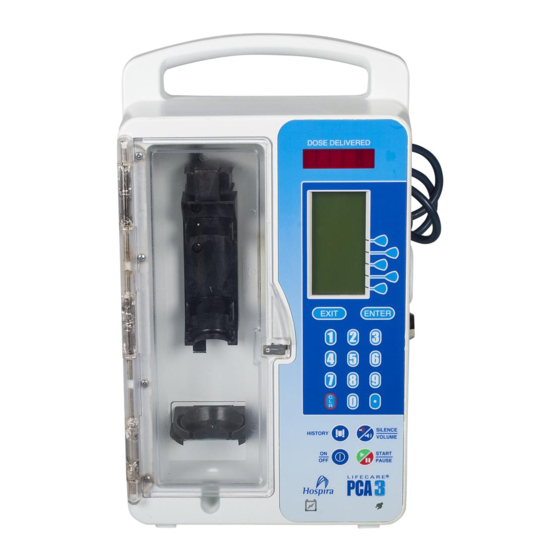
Summary of Contents for Hospira LifeCare PCA3
- Page 1 HOSPIRA TECHNICAL SUPPORT OPERATIONS TECHNICAL SUPPORT OPERATIONS ELECTRONIC TECHNICAL SERVICE MANUAL ELECTRONIC TECHNICAL SERVICE MANUAL LifeCare PCA3 Infusion System EPS-04566-003 (REV. 1/05)
- Page 2 ® L I F E C A R E Infusion System For use with list number 12384-04 Technical Service Manual 430-04566-003 (Rev. 1/05)
- Page 3 © 2005 Hospira, Inc. This document and the subject matter disclosed herein are proprietary information. Hospira retains all the exclusive rights of dissemination, reproduction, manufacture, and sale. Any party using this document accepts it in confidence, and agrees not to duplicate it in whole or in part nor disclose it to others without the written consent of Hospira.
- Page 4 430-04566-002 (Rev. 08/03) Second Issue Updated and revised throughout 430-04566-003 (Rev. 1/05) Third Issue Incorporated Hospira name change. Updated Section 1 self test screens. Updated Section 5 self test screens. Updated Delivery Accuracy and Occlusion tests to current specifications. Updated Section 7 procedures to accomodate new parts.
- Page 5 CHANGE HISTORY This page intentionally left blank. 430-04566-003 (Rev. 1/05) LifeCare PCA3 Infusion System...
-
Page 6: Table Of Contents
CONTENTS Contents Section 1 INTRODUCTION ......1.1 SCOPE ......1.2 CONVENTIONS . - Page 7 7.2.2 SEPARATING THE FRONT AND REAR ENCLOSURE ASSEMBLIES . . 7.2.3 INJECTOR SENSOR SWITCH ADJUSTMENT ..7.2.4 VIAL SENSOR SWITCH ADJUSTMENT ... . 430-04566-003 (Rev. 1/05) LifeCare PCA3 Infusion System...
- Page 8 CONTENTS 7.2.5 OCCLUSION ALARM SWITCH TEST AND ADJUSTMENT ....7.2.5.1 OCCLUSION ALARM SWITCH TEST ..7.2.5.2 OCCLUSION ALARM SWITCH AND PRESSURE ADJUSTMENT .
- Page 9 Table 9-1. Drawings ....... Table 9-2. Illustrated Parts Breakdown ..... . . 430-04566-003 (Rev. 1/05) LifeCare PCA3 Infusion System...
-
Page 10: Introduction
❏ Technical Service Bulletins If a problem in device operation cannot be resolved using the information in this manual, contact Hospira (see Section 6.1, Technical Assistance). Specific instructions for operating the device are contained in the PCA 3 System Operating Manual. -
Page 11: Conventions
SECTION 1 INTRODUCTION CONVENTIONS The conventions listed in Conventions, are used throughout this manual. Table 1-1, Table 1-1. Conventions Convention Application Example Italic Reference to a section, figure, (see Section 6.1, Technical table, or publication Assistance) [ALL CAPS] In-text references to keys [SILENCE] and touchswitches ALL CAPS... -
Page 12: Acronyms And Abbreviations
1.4 ACRONYMS AND ABBREVIATIONS ACRONYMS AND ABBREVIATIONS Acronyms and abbreviations used in this manual are as follows: A Ampere AC Alternating current ADC Analog-to-digital converter BCR Barcode reader CMOS Complementary metal-oxide semiconductor CPU Central processing unit dB Decibel DC Direct current DPM Digital pressure meter DSLR Display start line register ECG Electrocardiograph... -
Page 13: User Qualification
SECTION 1 INTRODUCTION PCL Power control logic psi Pounds per square inch PVT Performance verification test PWA Printed wiring assembly RAM Random access memory ROM Read only memory RTC Real-time clock SLA Sealed lead acid SPDT Single pole double throw SPI Serial peripheral interface SRAM Static random access memory UART Universal asynchronous receiver transmitter... -
Page 14: Instrument Installation Procedure
1.7 INSTRUMENT INSTALLATION PROCEDURE INSTRUMENT INSTALLATION PROCEDURE CAUTION: Infusion pump damage may occur unless proper care is exercised during product unpacking and installation. The battery may not be fully charged upon receipt of the infusion pump. Do not place the infusion pump in service if it fails the self test. -
Page 15: Inspection
CAUTION: Inspect the infusion pump for evidence of damage. Do not use the pump if it appears to be damaged. Should damage be found, contact Hospira (see Section 6.1, Technical Assistance). Inspect the infusion pump periodically for signs of defects such as worn accessories, broken connections, or damaged cable assemblies. -
Page 16: Setting The Time And Date
DATE: 11/12/02 FLASH . . OK CPU ID . OK SOFTWARE CPU ..OK V4.09 TIMER . . OK COPYRIGHT HOSPIRA INC. SYSTEM 2004 SETTINGS CONTINUE 00K06001 Figure 1-1. PCA 3 Self Test Screens 1.7.4 SETTING THE TIME AND DATE... -
Page 17: Figure 1-2. Setting The Time And Date
SECTION 1 INTRODUCTION 13. Press the [ON/OFF] softkey when correct time and date are displayed. SET TIME WITH WARNING SELECT NUMBERS SETTING BUTTONS TO CHANGE CHANGING THE TOGGLE AM/PM DATE OR TIME 10:43 PM VOLUME WILL CLEAR ALL TOTALS CONTRAST TIME/DATE CONTINUE AM/PM... -
Page 18: Warranty
(whether such cause be based in contract, negligence, strict liability, other tort, or otherwise) exceed the price of such product, and in no event shall Hospira be liable for incidental, consequential, or special damages or losses or for lost business, revenues, or profits. - Page 19 SECTION 2 WARRANTY This page intentionally left blank. 430-04566-003 (Rev. 1/05) 2 - 2 LifeCare PCA 3 Infusion System...
-
Page 20: System Operating Manual
A copy of the system operating manual is included with every LifeCare PCA 3 infusion system. Insert a copy here for convenient reference. If a copy of the system operating manual is not available, contact Hospira Technical Support Operations (see Section 6.1, Technical Assistance). - Page 21 SECTION 3 SYSTEM OPERATING MANUAL This page intentionally left blank. 430-04566-003 (Rev. 1/05) 3 - 2 LifeCare PCA 3 Infusion System...
-
Page 22: Theory Of Operation
Section 4 THEORY OF OPERATION This section describes the PCA 3 infusion system theory of operation. Related drawings are provided in Drawings. The theory of operation details the general description, Section 9, electronics overview, and mechanism assembly. GENERAL DESCRIPTION The PCA 3 includes the following features: ❏... -
Page 23: Electronics Overview
SECTION 4 THEORY OF OPERATION ELECTRONICS OVERVIEW PCA 3 infusion system electronics include the power supply module; supervision circuitry; battery charger; logic interface; LCD interface; keypad interface; serial port; barcode reader; patient pendant; real-time clock; alarm logic; and memory. 4.2.1 POWER SUPPLY MODULE The power supply module provides regulated DC power to the pump electronics from the AC mains. -
Page 24: Power Control Logic Circuitry
4.2 ELECTRONICS OVERVIEW 4.2.2.3 POWER CONTROL LOGIC CIRCUITRY The power control logic (PCL) controls the logic power switch. Any of four events initiate power-up: AC Power-On (AC_ON), SWon* (front panel Power-On), VialSw* (vial switch), or InjSw* (injector clamp switch). The switch inputs are normally open circuit and pulled high to V3.3. -
Page 25: Lithium Battery Backup
SECTION 4 THEORY OF OPERATION 4.2.5 LITHIUM BATTERY BACKUP A lithium “coin cell” battery provides emergency standby power to the RTC and SRAM if the SLA battery is disabled and AC power is off. The lithium battery discharge current will be less than 26 µA at approximately 25°C temperature. -
Page 26: Discharged Battery Detection
4.2 ELECTRONICS OVERVIEW 4.2.6.2 DISCHARGED BATTERY DETECTION If, during operation on battery (no AC power, charger off), the terminal voltage falls below 7.2 volts (owing to IR drops internal to the battery and fuse, while the cell voltage is actually 7.8 volts) for more than 3 seconds, the battery is discharged, and the “DEAD BATTERY”... -
Page 27: Lcd Interface
SECTION 4 THEORY OF OPERATION 4.2.8 LCD INTERFACE A 128 x 64 pixel LCD in portrait orientation is the main user display. The LCD module is based on two Hitachi HD61202 (or similar) column drivers. This is a CMOS logic operating from the 5 volt supply. -
Page 28: Ac Power Indicator
4.2 ELECTRONICS OVERVIEW 4.2.8.5 AC POWER INDICATOR A green LED light bar back-illuminates the AC power graphic symbol on the front panel. The AC power indicator is active anytime +12V is present, and is not controlled by the MCU. The AC power indicator draws approximately 10 mA. 4.2.9 KEYPAD INTERFACE A keypad is used for operator control and data entry. -
Page 29: Patient Pendant
SECTION 4 THEORY OF OPERATION 4.2.12 PATIENT PENDANT The patient pendant is a normally open SPDT switch connected to the infusion pump with a 1/4 inch stereo phone jack. The sleeve contact of the phone jack is at common, the tip contact is the normally open signal PCA*. -
Page 30: Mechanism Assembly
4.2 ELECTRONICS OVERVIEW 4.2.14 MECHANISM ASSEMBLY The mechanism assembly drives an inverted syringe from a lead screw and stepper motor drive. Sensors in the mechanism monitor the syringe, drive position, and loading force (see Figure 4-1, Mechanism Assembly). 00G06004 Figure 4-1. Mechanism Assembly Technical Service Manual 4 - 9 430-04566-003 (Rev. -
Page 31: Vial Sensor
SECTION 4 THEORY OF OPERATION 4.2.14.1 VIAL SENSOR The vial sensor is a normally open SPDT switch behind the cradle that moves as the syringe is emptied. The normally closed contact is not used. A harness connects the sensor to the MCU PWA. -
Page 32: Dual Bipolar Drive
4.2 ELECTRONICS OVERVIEW 4.2.14.6 DUAL BIPOLAR DRIVE The motor drive is a major current drain in the operation of the infusion pump. To conserve power, a bipolar constant current drive is used. This motor has two windings that are electrically 90° out of phase (see Figure 4-2, Dual Bipolar Drive). -
Page 33: Alarm Logic
SECTION 4 THEORY OF OPERATION 4.2.16 ALARM LOGIC Refer to 6. The MCU PWA controls an Figure 9-7, MCU PWA Schematic (Analog), Sheet 5 of audible buzzer that is activated either under software control, during MCU reset period, or under catastrophic failure. 4.2.16.1 NORMAL ALARM The alarm will sound each time the PCA 3 powers on. -
Page 34: Normal Key Tone
4.2 ELECTRONICS OVERVIEW 4.2.16.6 NORMAL KEY TONE Activating the alarm for 10 to 50 ms at medium volume will indicate valid keypad input. 4.2.17 PROGRAM MEMORY The program code is stored in a 256 K x 16 flash ROM. The flash memory is to be erased and rewritten in-circuit. - Page 35 SECTION 4 THEORY OF OPERATION This page intentionally left blank. 430-04566-003 (Rev. 1/05) 4 - 14 LifeCare PCA 3 Infusion System...
-
Page 36: Maintenance And Service Tests
Section 5 MAINTENANCE AND SERVICE TESTS A complete maintenance program promotes infusion pump longevity and trouble-free instrument operation. Such a program should include routine maintenance, periodic maintenance inspection, and following any repair procedure, performance verification testing. ROUTINE MAINTENANCE Routine maintenance consists of basic inspection and cleaning procedures. As a minimum requirement, inspect and clean the infusion pump after each use. -
Page 37: Sanitizing
CAUTION: Certain cleaning and sanitizing compounds may slowly degrade components made from some plastic materials. Using abrasive cleaners or cleaning solutions not recommended by Hospira may result in product damage and, potentially, void the product warranty. Do not use compounds containing combinations of isopropyl alcohol and dimethyl benzyl ammonium chloride. -
Page 38: Performance Verification Test
Perform the PVT before an infusion pump is placed back in service after repair. If any malfunction is detected as a result of the PVT, contact Hospira. Note: Perform the PVT exactly as described in this manual to assure effective and reliable product evaluation information. -
Page 39: Test Setup
2. Plug the AC power cord into a grounded, hospital-grade 120 V , 50-60 Hz receptacle. 3. Connect the appropriate Hospira PCA set to a Hospira 30 mL PCA vial/injector. CAUTION: Make certain all caps on the vial and the administration set are removed and all clamps are open when priming. -
Page 40: Service Mode Tests
4. Verify the Service Mode screen displays. The Service Mode screen includes the current software version and the total elapsed days since new software was downloaded or the pump was initialized in Hospira Mode. Press the [CONTINUE] softkey. 5. Verify the infusion pump is not connected to a patient and press the [CONTINUE] softkey. -
Page 41: Table 5-2. System Tests
SECTION 5 MAINTENANCE AND SERVICE TESTS 6. After the power up RAM test is completed, the infusion pump displays the Service Mode Main Menu screen. Press the [MAINTENANCE] softkey. 7. Press the [SYSTEM TEST] softkey. 8. Select the test to be performed by pressing the corresponding softkey (see Table 5-2). -
Page 42: Delivery Accuracy Test
5.2 PERFORMANCE VERIFICATION TEST 5.2.6 DELIVERY ACCURACY TEST To perform the delivery accuracy test, proceed as follows: 1. Unlock and open the security door. 2. With the cradle in the uppermost position, insert a water-filled, primed PCA 3 vial and PCA 3 set, with a 21-gauge butterfly, into the cradle. 3. -
Page 43: Occlusion Test
SECTION 5 MAINTENANCE AND SERVICE TESTS 24. Once the second loading dose is completed, verify the infusion pump delivered 20mL ± 1 mL. 25. Remove the blunt cannula or needle from the distal end of the PCA 3 set. 26. Press the [ON/OFF] touchswitch to power off the pump. 5.2.7 OCCLUSION TEST To perform the occlusion test, proceed as follows:... -
Page 44: Electrical Safety Test
2. Reset the PCA 3 infusion system to the original configuration. 3. Verify the correct time and date. 4. Return the PCA 3 infusion system to service. Note: If any tests fail, refer to Troubleshooting, or contact Hospira. Section 6, Technical Service Manual 5 - 9 430-04566-003 (Rev. 1/05) -
Page 45: Printer Test (Optional)
SECTION 5 MAINTENANCE AND SERVICE TESTS PRINTER TEST (OPTIONAL) To perform the printer test, proceed as follows: 1. Connect a serial printer cable to the printer port on the infusion pump. 2. Power on the printer. Press the printer [ON-LINE] switch and verify the on-line LED lights. -
Page 46: Battery Operation Overview
5.5 BATTERY OPERATION OVERVIEW BATTERY OPERATION OVERVIEW The infusion pump is intended to operate on battery power on an exception basis only, such as emergency backup or temporary portable operation. Examples of emergency backup include AC power failure or inadvertent disconnection of the AC power cord. An instance of temporary portable operation includes patient transfer from one location to another. - Page 47 SECTION 5 MAINTENANCE AND SERVICE TESTS This page intentionally left blank. 430-04566-003 (Rev. 1/05) 5 - 12 LifeCare PCA 3 Infusion System...
-
Page 48: Troubleshooting
755 Jarvis Drive Morgan Hill, California 95037 For technical assistance, product return authorization, and to order parts, accessories, or manuals from outside the United States, contact the nearest Hospira sales office. DIAGNOSTIC MODE The diagnostic mode provides the following features: ❏... -
Page 49: Alarm Messages And Error Codes
SECTION 6 TROUBLESHOOTING To enter the diagnostic mode, refer to the PCA 3 System Configuration Guide and proceed as follows: 1. Confirm the AC power indicator (AC plug) on the front panel is illuminated. 2. Unlock and open the security door. 3. -
Page 50: Table 6-1. Operational Alarm Messages
6.3 ALARM MESSAGES AND ERROR CODES Note: Operational alarm messages are displayed on the LCD screen. Associated error codes are displayed in the alarm history. Table 6-1. Operational Alarm Messages Alarm Message Possible Cause Corrective Action Check Settings Door secured on any screen other Open the door, check therapy than the Press Start to Begin settings, finish programming... -
Page 51: Error Codes Requiring Technical Service
SECTION 6 TROUBLESHOOTING Table 6-1. Operational Alarm Messages Alarm Message Possible Cause Corrective Action Door Open Door left open or unlocked for more Close and lock the door than two minutes Infuser Paused Infusion stopped by pressing Press [START/PAUSE] again, [START/PAUSE] or unlock door Low Battery... - Page 52 Motor Step Time Error Motor step time out of range Rate Unexpected rate Delivery Volume Error Volume infused Contact Hospira is out of range 5-Volt Error Two readings outside the Replace power supply range of 4.7 V - 5.3 V (see Section 7.3.9.4)
- Page 53 AC (mains) power Replace lithium battery (see Section 7.3.8.10.6) Replace battery (see Section 7.3.6) If malfunction cannot be cleared, contact Hospira Flash Checksum Error Failed checksum at Replace MCU PWA startup or during (see Section 7.3.8.10.5) operation Motor State Invalid rate or restart.
- Page 54 6.3 ALARM MESSAGES AND ERROR CODES Table 6-2. Error Codes Requiring Technical Service Alarm Possible Corrective Code Malfunction Description Cause Action Mirror Data Mismatched Data in RAM does not Replace lithium battery match data in FLASH (see Section 7.3.8.10.6) Replace MCU PWA (see Section 7.3.8.10.5) UI State Error User interface state ID...
- Page 55 SECTION 6 TROUBLESHOOTING Table 6-2. Error Codes Requiring Technical Service Alarm Possible Corrective Code Malfunction Description Cause Action Clock RAM Error Data or address Replace MCU PWA communication errors (see Section 7.3.8.10.5) External RAM Error Failed read/write operations on external LCD Backlight Backlight current Verify LCD assembly...
- Page 56 6.3 ALARM MESSAGES AND ERROR CODES Table 6-2. Error Codes Requiring Technical Service Alarm Possible Corrective Code Malfunction Description Cause Action LCD Timeout Error LCD does not Verify LCD assembly acknowledge data within connections to MCU hardware specific-time Replace LCD assembly (see Section 7.3.8.10.2) Replace MCU PWA (see Section 7.3.8.10.5)
-
Page 57: Troubleshooting Procedures
Table 6-3, Troubleshooting with the reference, probable cause, and corrective actions. If, after completing Steps 1 and 2, a malfunction has not been located, or if the infusion pump persistently fails, contact Hospira Technical Support Operations. 430-04566-003 (Rev. 1/05) 6 - 10... -
Page 58: Table 6-3. Troubleshooting With The Pvt
Test Failure Probable Cause Corrective Action Self Test Power off infusion pump, then power on (Section 5.2.4) If error recurs, contact Hospira Service Mode Tests Defective MCU PWA Replace MCU PWA (Section 5.2.5) (Section 7.3.8.10.5) (see Table 5-2) IN RAM... - Page 59 SECTION 6 TROUBLESHOOTING Table 6-3. Troubleshooting with the PVT Test Failure Probable Cause Corrective Action DOOR Defective door lock Replace door lock assembly assembly (Section 7.3.8.7) Defective MCU PWA Replace MCU PWA (Section 7.3.8.10.5) SYRINGE Defective mechanism Adjust vial sensor switch assembly (Section 7.2.4) Replace mechanism assembly...
-
Page 60: Replaceable Parts And Repairs
Figure 9-1. To request a copy of the current spare parts price list, contact Hospira Technical Support Operations (see Section 6.1), or to view the catalog online, visit the website at: www.hospiraparts.com For convenient reference, insert a copy of the spare parts price list here. - Page 61 SECTION 7 REPLACEABLE PARTS AND REPAIRS This page intentionally left blank. 430-04566-003 (Rev. 1/05) 7 - 2 LifeCare PCA 3 Infusion System...
-
Page 62: Adjustment Procedures
7.2 ADJUSTMENT PROCEDURES ADJUSTMENT PROCEDURES WARNING: UNLESS OTHERWISE INDICATED, DISCONNECT THE INFUSION PUMP FROM AC POWER BEFORE PERFORMING ADJUSTMENT OR REPLACEMENT PROCEDURES. CAUTION: Use proper ESD grounding techniques when handling components. Wear an antistatic wrist strap and use an ESD-protected workstation. Store PWAs in antistatic bags before placing them on any surface. -
Page 63: Separating The Front And Rear Enclosure Assemblies
SECTION 7 REPLACEABLE PARTS AND REPAIRS 7.2.2 SEPARATING THE FRONT AND REAR ENCLOSURE ASSEMBLIES The front and rear enclosure assemblies must be separated before performing any adjustment procedure. The recommended tool for this procedure is a No. 2 Phillips screwdriver. To separate the front and rear enclosure assemblies, refer to Figure 7-1, Assemblies, and... -
Page 64: Injector Sensor Switch Adjustment
7.2 ADJUSTMENT PROCEDURES #6 LOCK WASHER (4) FRONT ENCLOSURE 6-32 x 1/2 PAN HEAD SCREW (4) REAR ENCLOSURE 00K06006 Figure 7-1. Separating the Front and Rear Enclosure Assemblies 7.2.3 INJECTOR SENSOR SWITCH ADJUSTMENT The recommended tools and materials for this procedure are a 3/16 inch nutdriver and red GLPT insulating varnish. -
Page 65: Vial Sensor Switch Adjustment
SECTION 7 REPLACEABLE PARTS AND REPAIRS MOTOR ASSEMBLY SWITCH MOUNTING SCREW (2) FRONT ENCLOSURE 00K06039 Figure 7-2. Injector Sensor Switch 7.2.4 VIAL SENSOR SWITCH ADJUSTMENT The recommended tools and materials for this procedure are a 3/16 inch nutdriver and red GLPT insulating varnish. -
Page 66: Occlusion Alarm Switch Test And Adjustment
7.2 ADJUSTMENT PROCEDURES VIAL SENSOR SWITCH VIAL SENSOR ROD VIAL SENSOR SWITCH ACTUATOR ARM 00K06040 Figure 7-3. Vial Sensor Switch 7.2.5 OCCLUSION ALARM SWITCH TEST AND ADJUSTMENT The recommended tools and materials for the following procedures are a No. 0 Phillips screwdriver;... -
Page 67: Adjustment
SECTION 7 REPLACEABLE PARTS AND REPAIRS 8. Verify the “DISCONNECT SET FROM PATIENT/PRESS AND HOLD PURGE KEY” message is displayed. Press and hold the [PURGE] softkey until flow is seen at the three-way stopcock. Release the [PURGE] softkey. 9. Verify the “PURGE COMPLETE?” message is displayed. Check for air-in-line and assure the set is primed, then press [YES]. -
Page 68: Figure 7-4. Occlusion Alarm Test Setup
7.2 ADJUSTMENT PROCEDURES WATER FILLED VIAL STOPCOCK UNIVERSAL PRESSURE METER PRESSURE INPUT 0.00 cm OF H O INCHES OF H O -13.5 TO 15 mmHg - 13.5 TO 75 SILENCE HISTORY VOLUME START PAUSE L I F E C A R E ®... -
Page 69: Lead Screw Lubrication
SECTION 7 REPLACEABLE PARTS AND REPAIRS 6. If the occlusion alarm does not sound at or before 20 psi, relieve the fluid pressure by opening the stopcock valve. Loosen the set screw on the thumb nut and turn the thumb nut counter clockwise to loosen. Repeat steps 4 and 5. 7. -
Page 70: Replacement Procedures
7.3 REPLACEMENT PROCEDURES REPLACEMENT PROCEDURES This section contains safety and equipment precautions, required tools and materials, and step-by-step procedures for replacing parts in the infusion pump. Unless otherwise stated, always perform the PVT after a replacement procedure. 7.3.1 SAFETY AND EQUIPMENT PRECAUTIONS Before opening the front enclosure of the infusion pump, take all necessary precautions for working on high-voltage equipment. -
Page 71: Front And Rear Enclosure Replacement
SECTION 7 REPLACEABLE PARTS AND REPAIRS 7.3.3 FRONT AND REAR ENCLOSURE REPLACEMENT The recommended tool for this procedure is a No. 2 Phillips screwdriver. The replacement parts for this procedure are: Enclosure, Front Enclosure, Rear Screw, 6-32 x 1/2, Pan Head, Phillips Washer, Lock, #6 To replace the front and rear enclosure assemblies, refer to 7-1, then proceed... -
Page 72: Rubber Foot Pad Replacement
7.3 REPLACEMENT PROCEDURES 7.3.4 RUBBER FOOT PAD REPLACEMENT Recommended tools and materials for this procedure are an X-acto knife and isopropyl alcohol. The following replacement part is available: Pad, Rubber Foot To replace the rubber foot pad, refer to 7-6, then proceed as follows: Figure 1. -
Page 73: Figure 7-6. Battery Assembly, Ac Power Cord, And Patient Pendant Assembly
SECTION 7 REPLACEABLE PARTS AND REPAIRS #6 LOCK FRONT ENCLOSURE WASHER (5) 6-32 x 1/2 PAN HEAD SCREW (4) BATTERY ASSEMBLY PATIENT PENDANT ASSEMBLY RUBBER FOOT PAD (4) REAR ENCLOSURE BATTERY DOOR PAD BATTERY DOOR AC POWER CORDSET 6-32 x 1/4 PAN HEAD SCREW 00K06021 Figure 7-6. -
Page 74: Ac Power Cord Replacement
7.3 REPLACEMENT PROCEDURES 7.3.5 AC POWER CORD REPLACEMENT The recommended tool for this procedure is a No. 2 Phillips screwdriver. The following replacement part is available: Cordset, AC Power, Hospital Grade To replace the AC power cord, refer to 7-6, then proceed as follows: Figure 1. - Page 75 SECTION 7 REPLACEABLE PARTS AND REPAIRS 5. Install the replacement battery strap in the exact reverse order of removal. 6. Pull the battery wire harness and cable outside the enclosure. Disconnect the battery assembly from the infusion pump. Pull up on the battery strap and remove the battery from the enclosure.
-
Page 76: Front Enclosure Assembly Component Replacement
7.3 REPLACEMENT PROCEDURES 7.3.8 FRONT ENCLOSURE ASSEMBLY COMPONENT REPLACEMENT Front enclosure assembly component replacement includes replacement of the following: ❏ Security door ❏ Handle gasket ❏ Door hinge ❏ Enclosure gasket ❏ Keypad ❏ Electronics assembly and components ❏ Door latch hook ❏... -
Page 77: Figure 7-7. Front Enclosure Assembly External Components
SECTION 7 REPLACEABLE PARTS AND REPAIRS FRONT ENCLOSURE CRADLE ASSEMBLY 6-24 x 5/8 PAN HEAD SCREW (2) DOOR HINGE 4-40 x 3/8 PAN HEAD SCREW (4) 4-40 x 3/16 FLAT HEAD SCREW DOOR LATCH HOOK SECURITY DOOR KEYPAD 00K06046 Figure 7-7. Front Enclosure Assembly External Components 430-04566-003 (Rev. -
Page 78: Keypad Replacement
7.3 REPLACEMENT PROCEDURES 7.3.8.2 KEYPAD REPLACEMENT Recommended tools and materials for this procedure are a 1/4 inch nutdriver, an X-acto knife, isopropyl alcohol, and a lint-free cloth. The following replacement part is available: Keypad Bracket, Grounding, Keypad To replace the keypad, refer to 7-8, then proceed as follows: Figure 7-7 Figure... -
Page 79: Door Latch Hook Replacement
SECTION 7 REPLACEABLE PARTS AND REPAIRS 7.3.8.3 DOOR LATCH HOOK REPLACEMENT The recommended tool for this procedure is a No. 1 Phillips screwdriver. The replacement parts for this procedure are: Hook, Door Latch Screw, 4-40 x 3/16, Flat Head, Phillips To replace the door latch hook, refer to 7-7, then proceed as follows: Figure... -
Page 80: Mechanism Lever Arm Replacement
7.3 REPLACEMENT PROCEDURES 7.3.8.5 MECHANISM LEVER ARM REPLACEMENT The recommended tool for this procedure is a medium size flat blade screwdriver. The following replacement part is available: Arm, Lever, Mechanism To replace the mechanism lever arm, refer to 7-8, then proceed as follows: Figure 1. -
Page 81: Figure 7-8. Front Enclosure Assembly Internal Components
SECTION 7 REPLACEABLE PARTS AND REPAIRS MECHANISM LEVER ARM FRONT ENCLOSURE BARCODE READER AND BRACKET FOAM PAD (2) BARCODE READER LITHIUM WINDOW WINDOW BATTERY BARCODE READER GASKET 6-32 x 5/16 HEX HEAD SCREW (7) DOOR LOCK ASSEMBLY 10-32 x 1 HEX HEAD SCREW (2) HANDLE GASKET... -
Page 82: Door Latch Assembly Replacement
7.3 REPLACEMENT PROCEDURES 7.3.8.6 DOOR LATCH ASSEMBLY REPLACEMENT Recommended tools for this procedure are a 7/8 inch open end wrench, medium size flat blade screwdriver, and 1/4 inch nutdriver. The replacement parts for this procedure are: Assembly, Door Latch Screw, 6-32 x 5/16, Hex Head, with Washer To replace the door latch assembly, refer to 7-8, then proceed as follows: Figure... -
Page 83: Figure 7-9. Door Lock Assembly
SECTION 7 REPLACEABLE PARTS AND REPAIRS 3. Using the 7/16 open end wrench, tighten the nut over the washers. 4. Using the needle nose pliers, bend the washer fingers up to hold the nut in place. 5. Holding the lock in your right hand, insert the key into the lock and verify that the key turns 90 degrees to the left. -
Page 84: Handle Gasket And Enclosure Gasket Replacement
7.3 REPLACEMENT PROCEDURES 7.3.8.8 HANDLE GASKET AND ENCLOSURE GASKET REPLACEMENT The recommended tool for this procedure is an X-acto knife. The replacement parts for this procedure are: Gasket, Handle Gasket, Enclosure To replace the handle and enclosure gaskets, refer to 7-8, then proceed as follows: Figure 1. -
Page 85: Electronics Assembly Component Replacement
SECTION 7 REPLACEABLE PARTS AND REPAIRS 5. Grasp the ribbon connector locking tabs of J10 and J11 and pull up to disengage. Disconnect the ribbon cables from the MCU PWA. Disengage the connectors attaching J13, J16, and J18 to the MCU PWA. 6. -
Page 86: Figure 7-10. Electronics Assembly Components
7.3 REPLACEMENT PROCEDURES MCU PWA NYLON HARDWARE POST (4) NUMERIC DISPLAY PWA NYLON HARDWARE POST (4) LCD ASSEMBLY ICON DISPLAY PWA LCD SHIELD 00K06022 Figure 7-10. Electronics Assembly Components 7.3.8.10.1 LCD Shield Replacement Recommended tools and materials for this procedure are an X-acto knife, isopropyl alcohol, and a lint-free cloth. - Page 87 SECTION 7 REPLACEABLE PARTS AND REPAIRS 7.3.8.10.2 LCD Assembly Replacement The recommended tools for this procedure are diagonal cutters and needle nose pliers. The replacement parts for this procedure are: Assembly, LCD Post, Nylon To replace the LCD assembly, refer to 7-10, then proceed as follows: Figure 7-8 Figure...
- Page 88 7.3 REPLACEMENT PROCEDURES 7.3.8.10.3 Numeric Display PWA Replacement CAUTION: Use proper ESD grounding techniques when handling components. Wear an antistatic wrist strap and use an ESD-protected workstation. Store the PWA in an antistatic bag before placing it on any surface. The recommended tools for this procedure are diagonal cutters and needle nose pliers.
- Page 89 SECTION 7 REPLACEABLE PARTS AND REPAIRS 7.3.8.10.4 Icon Display PWA Replacement CAUTION: Use proper ESD grounding techniques when handling components. Wear an antistatic wrist strap and use an ESD-protected workstation. Store the PWA in an antistatic bag before placing it on any surface. The recommended tools for this procedure are diagonal cutters and needle nose pliers.
- Page 90 7.3 REPLACEMENT PROCEDURES 7.3.8.10.5 MCU PWA Replacement CAUTION: Use proper ESD grounding techniques when handling components. Wear an antistatic wrist strap and use an ESD-protected workstation. Store the PWA in an antistatic bag before placing it on any surface. Note: Replacing the MCU PWA removes the pump’s serial number from memory.
-
Page 91: Mechanism Assembly Replacement
SECTION 7 REPLACEABLE PARTS AND REPAIRS 4. Remove the lithium battery by grasping it with thumb and forefinger, rotating slightly clockwise, and pulling up and to the left. 5. Observing polarity (+ side down), align the replacement lithium battery with the battery holder and push straight down until the battery snaps into place. -
Page 92: Barcode Reader, Gasket, And Window Replacement
7.3 REPLACEMENT PROCEDURES 5. Disconnect the three mechanism cables from the MCU PWA. 6. Place the infusion pump face down on a soft surface. Using the nutdriver, remove the three 10-32 screws that secure the mechanism assembly to the front enclosure. 7. -
Page 93: Rear Enclosure Assembly Component Replacement
SECTION 7 REPLACEABLE PARTS AND REPAIRS 7.3.8.14 SPLASH SHIELD REPLACEMENT The recommended tool for this procedure is an X-acto knife. The following replacement part is available: Shield, Splash To replace the splash shield, refer to 7-8, then proceed as follows: Figure 1. -
Page 94: Figure 7-11. Rear Enclosure External Components
7.3 REPLACEMENT PROCEDURES REAR ENCLOSURE 4-40 SCREWLOCK (2) 6-32 x 1/4 EQUIPOTENTIAL POST FLAT HEAD SCREW (2) #4 FLAT WASHER 4-24 x 3/8 THREAD CUTTING SCREW POLE CLAMP ASSEMBLY 8-32 x 3/8 FLAT HEAD SCREW (4) AC PLUG STRAP CONNECTOR RETAINER PLATE (2) FUSE (2) -
Page 95: Fuse Replacement
SECTION 7 REPLACEABLE PARTS AND REPAIRS 7.3.9.1 FUSE REPLACEMENT The recommended tools for this procedure are a No. 2 Phillips screwdriver and a small flat blade screwdriver. The following replacement part is available: Fuse, .5 A, 250 V, Slo-Blo To replace the fuses, refer to 7-11, then proceed as follows: Figure 1. -
Page 96: Velcro Strap And Retainer Plate Replacement
7.3 REPLACEMENT PROCEDURES 5. Install the replacement pole clamp assembly using the screws and lock washers that were removed in step 3. 6. Connect the infusion pump to AC power. Replacement of the pole clamp assembly is routine maintenance and no verification procedure is normally required. -
Page 97: Power Supply Pwa Replacement
SECTION 7 REPLACEABLE PARTS AND REPAIRS 7.3.9.4 POWER SUPPLY PWA REPLACEMENT CAUTION: Use proper ESD grounding techniques when handling components. Wear an antistatic wrist strap and use an ESD-protected workstation. Store the PWA in an antistatic bag before placing it on any surface. The recommended tools for this procedure are a 3/16 inch nutdriver and a 1/4 inch nutdriver. -
Page 98: Rear Enclosure Harness Assembly, Equipotential Post, And Ground Strap Replacement
7.3 REPLACEMENT PROCEDURES 5. Install the replacement pawl/ratchet assembly in the exact reverse order of removal. 6. Reassemble the infusion pump in the exact reverse order of disassembly. 7. Connect the infusion pump to AC power. To verify successful replacement of the pawl/ratchet assembly, perform the PVT Section 5.2. -
Page 99: Battery Pad Replacement
SECTION 7 REPLACEABLE PARTS AND REPAIRS PATIENT PENDANT JACK ASSEMBLY SPIRAL WRAP CABLE TIES REAR ENCLOSURE REAR ENCLOSURE HARNESS ASSEMBLY ASSEMBLY 00K06047 Figure 7-12. Rear Enclosure Harness Assembly 7.3.9.7 BATTERY PAD REPLACEMENT Recommended tools and materials for this procedure are an X-acto knife, isopropyl alcohol, and a lint-free cloth. -
Page 100: Serial Port Cable Assembly Replacement
7.3 REPLACEMENT PROCEDURES 7.3.9.8 SERIAL PORT CABLE ASSEMBLY REPLACEMENT The recommended tool for this procedure is a 3/16 inch nutdriver. The replacement parts for this procedure are: Assembly, Cable, Serial Port Seal, Connector, Serial Port Strap, Ground, Interface Panel Nut, Hex, 4-40 Washer, Lock, #4 Screwlock, 4-40, M/F, Hex To replace the serial port cable assembly, refer to... -
Page 101: Patient Pendant Jack Assembly Replacement
SECTION 7 REPLACEABLE PARTS AND REPAIRS 7.3.9.9 PATIENT PENDANT JACK ASSEMBLY REPLACEMENT Recommended tools for this procedure are a 1/2 inch nutdriver, diagonal cutters, and cable ties. The replacement parts for this procedure are: Assembly, Jack, Patient Pendant Tie, Cable To replace the patient pendant jack assembly, refer to Figure 7-12 Figure... - Page 102 7.3 REPLACEMENT PROCEDURES Technical Service Manual 7 - 43 430-04566-003 (Rev. 1/05)
- Page 103 SECTION 7 REPLACEABLE PARTS AND REPAIRS This page intentionally left blank. 430-04566-003 (Rev. 1/05) 7 - 44 LifeCare PCA 3 Infusion System...
-
Page 104: Specifications
Section 8 SPECIFICATIONS PHYSICAL Dimensions: Approximately 8 in. W x 13 in. H x 6 in. D (excluding pole clamp and power cord) Weight: Approximately 10 lbs. with battery Casing: High-impact plastic ELECTRICAL Power Requirements: 105-130 V, 57 - 63 Hz, 50 W Power Cord: Hospital-grade AC cord. - Page 105 SECTION 8 SPECIFICATIONS OCCLUSION ALARM AND LIMITS Backpressure Range: 10 to 20 psi MODES PCA Only: Approximately 1 mL in 35 seconds Continuous Only: Variable from 0.1 x concentration to 20 x concentration (mg/hr or mcg/hr) PCA + Continuous: Variable from 0.1 x concentration to 20 x concentration (mg/hr or mcg/hr) Lockout Interval Range: 5 to 120 minutes in one minute increments 430-04566-003 (Rev.
-
Page 106: Drawings
Section 9 DRAWINGS through show the illustrated parts breakdown (IPB), infusion pump Figure 9-1 Figure 9-9 assembly diagrams, and PWA schematic diagrams. Drawings, lists drawings by Table 9-1, figure number, title, and part number. Breakdown, identifies Table 9-2, Illustrated Parts parts by index numbers which correlate to Figure 9-1. - Page 107 SECTION 9 DRAWINGS Table 9-2. Illustrated Parts Breakdown Replacement Index No. Nomenclature Procedure PWA, MCU Section 7.3.8.10.5 PWA, Icon Display Section 7.3.8.10.4 Shield, LCD Section 7.3.8.10.1 Assembly, LCD Section 7.3.8.10.2 PWA, Numeric Display Section 7.3.8.10.3 PWA, Power Supply Section 7.3.9.4 Gasket, Enclosure Section 7.3.8.8 Gasket, Handle...
- Page 108 Table 9-2. Illustrated Parts Breakdown Replacement Index No. Nomenclature Procedure Pad, Battery Section 7.3.9.7 Window, LCD Section 7.3.8.11 Assembly, Door Latch Section 7.3.8.6 Assembly, Pawl/Ratchet Section 7.3.9.5 Assembly, Pole Clamp Section 7.3.9.2 Arm, Lever, Mechanism Section 7.3.8.5 Strap, Ground, Right Section 7.3.9.6 Strap, Ground, Left Section 7.3.9.6...
- Page 109 SECTION 9 DRAWINGS Table 9-2. Illustrated Parts Breakdown Replacement Index No. Nomenclature Procedure Screw, 6-32 x 1/4, Flat Head, Phillips As applicable Screw, 6-32 x 1/4, Pan Head, Phillips As applicable Screw, 6-32 x 1/2, Pan Head, Phillips As applicable Screw, 6-32 x 5/16, Hex Head, w/Washer As applicable Nut, M6, Hex, SS...
- Page 110 HOSPIRA, INC. 00K06049 Figure 9-1. Illustrated Parts Breakdown DRAWING NO. Rev. N/A NOT APPLICABLE Sheet 1 of 2 Technical Service Manual 9 - 5 430-04566-003 (Rev. 1/05)
- Page 111 SECTION 9 DRAWINGS This page intentionally left blank. 430-04566-003 (Rev. 1/05) 9 - 6 LifeCare PCA 3 Infusion System...
- Page 112 HOSPIRA, INC. Figure 9-1. Illustrated Parts Breakdown 00K06050 DRAWING NO. Rev. N/A NOT APPLICABLE Sheet 2 of 2 Technical Service Manual 9 - 7 430-04566-003 (Rev. 1/05)
- Page 113 SECTION 9 DRAWINGS This page intentionally left blank. 430-04566-003 (Rev. 1/05) 9 - 8 LifeCare PCA 3 Infusion System...
- Page 114 HOSPIRA, INC. Figure 9-2. Final Assembly DRAWING NO. Rev. N/A 00K06034 NOT APPLICABLE Sheet 1 of 1 Technical Service Manual 9 - 9 430-04566-003 (Rev. 1/05)
- Page 115 SECTION 9 DRAWINGS This page intentionally left blank. 430-04566-003 (Rev. 1/05) 9 - 10 LifeCare PCA 3 Infusion System...
- Page 116 HOSPIRA, INC. 00K06045 Figure 9-3. Front Enclosure Assembly DRAWING NO. Rev. N/A NOT APPLICABLE Sheet 1 of 2 Technical Service Manual 9 - 11 430-04566-003 (Rev. 1/05)
- Page 117 SECTION 9 DRAWINGS This page intentionally left blank. 430-04566-003 (Rev. 1/05) 9 - 12 LifeCare PCA 3 Infusion System...
- Page 118 HOSPIRA, INC. Figure 9-3. Front Enclosure Assembly 00K06033 DRAWING NO. Rev. N/A NOT APPLICABLE Sheet 2 of 2 Technical Service Manual 9 - 13 430-04566-003 (Rev. 1/05)
- Page 119 SECTION 9 DRAWINGS This page intentionally left blank. 430-04566-003 (Rev. 1/05) 9 - 14 LifeCare PCA 3 Infusion System...
- Page 120 HOSPIRA, INC. 00K06037 Figure 9-4. Rear Enclosure Assembly DRAWING NO. Rev. N/A NOT APPLICABLE Sheet 1 of 2 Technical Service Manual 9 - 15 430-04566-003 (Rev. 1/05)
- Page 121 SECTION 9 DRAWINGS This page intentionally left blank. 430-04566-003 (Rev. 1/05) 9 - 16 LifeCare PCA 3 Infusion System...
- Page 122 HOSPIRA, INC. HOSPIRA, INC. Figure 9-4. Rear Enclosure Assembly Figure 9-4. Rear Enclosure Assembly 00K06032 Rev. N/A DRAWING NO. DRAWING NO. Rev. N/A NOT APPLICABLE NOT APPLICABLE Sheet 2 of 2 Sheet 2 of 2 Technical Service Manual 9 - 17...
- Page 123 SECTION 9 DRAWINGS This page intentionally left blank. 430-04566-003 (Rev. 1/05) 9 - 18 LifeCare PCA 3 Infusion System...
- Page 124 HOSPIRA, INC. HOSPIRA, INC. Figure 9-5. Electronics Assembly (XLM with DataPort - Domestic) Figure 9-5. Electronics Assembly Rev. N/A DRAWING NO. DRAWING NO. Rev. N/A 00K06035 NOT APPLICABLE Sheet 1 of 1 NOT APPLICABLE Sheet 1 of 1 Technical Service Manual 9 - 19 430-04566-003 (Rev.
- Page 125 SECTION 9 DRAWINGS This page intentionally left blank. 430-04566-003 (Rev. 1/05) 9 - 20 LifeCare PCA 3 Infusion System...
- Page 126 HOSPIRA, INC. 00K06044 Figure 9-6. Mechanism Assembly DRAWING NO. Rev. N/A NOT APPLICABLE Sheet 1 of 1 Technical Service Manual 9 - 21 430-04566-003 (Rev. 1/05)
- Page 127 SECTION 9 DRAWINGS This page intentionally left blank. 430-04566-003 (Rev. 1/05) 9 - 22 LifeCare PCA 3 Infusion System...
- Page 128 0.1UF 0.1UF 0.1UF 0.1UF 0.1UF 0.1UF 0.1UF C105 0.1UF 0.1UF 0.IUF 0.1UF 0.1UF 0.1UF 0.1UF HOSPIRA, INC. Figure 9-7. MCU PWA Schematic DRAWING NO. Rev. A 249-04505-005 Sheet 1 of 6 Technical Service Manual 9 - 23 430-04566-003 (Rev. 1/05)
- Page 129 SECTION 9 DRAWINGS This page intentionally left blank. 430-04566-003 (Rev. 1/05) 9 - 24 LifeCare PCA 3 Infusion System...
- Page 130 3.0V TP 119 1/1W 1/10W TP 116 IRQO* TP 85 TP 81 0.1UF 0.1UF 0.01UF 0.01UF 1.00M ACON 2.00K HOSPIRA +12V 1.0UF 1/10W 1/10W 16V 10% 40.2K 11.5K VMOT Figure 9-7. MCU PWA Schematic 1/10W 1/10W 11.5K 1.62K (Microprocessor) 1% 1/10W 1% 1/10W DRAWING NO.
- Page 131 SECTION 9 DRAWINGS This page intentionally left blank. 430-04566-003 (Rev. 1/05) 9 - 26 LifeCare PCA 3 Infusion System...
- Page 132 TP 20 TP 45 10.0UF 1/10W 10.2K CONN_004P_ML 1/10W 0.22UF 3.16K 1.10W 0.1UF TP 19 LCD_VEE HOSPIRA, INC. TP 51 TP 48 BACKLIGHT 1/10W 1/10W Figure 9-7. MCU PWA Schematic 0.1UF 3.40K 0.1UF (LCD Interface) 1/10W DRAWING NO. Rev. A...
- Page 133 SECTION 9 DRAWINGS This page intentionally left blank. 430-04566-003 (Rev. 1/05) 9 - 28 LifeCare PCA 3 Infusion System...
- Page 134 1.00K 1/10W R119 10.0K R111 10.2K 1/10W SHAFT SENSOR 1/10W 1/10W 4 TP 343 TP 296 TP 289 HOSPIRA, INC. R117 2.55K 0.1UF C124 C130 74AHC1G14 LM 358 1/10W 0.01UF TP 291 TP 290 Figure 9-7. MCU PWA Schematic (I/O) R110 10.2K...
- Page 135 SECTION 9 DRAWINGS This page intentionally left blank. 430-04566-003 (Rev. 1/05) 9 - 30 LifeCare PCA 3 Infusion System...
- Page 136 R167 0.01UF 5.0K R 72 VALRM TP 234 TP 240 16 9K 4.02K TP 223 10.0K LM 358 HOSPIRA, INC. 1/10W 1/10W LM 358 1% 1/10W C104 0.033UF 0.022UF 0.1UF Figure 9-7. MCU PWA Schematic (Analog) -ALARM LOGIC- DRAWING NO.
- Page 137 SECTION 9 DRAWINGS This page intentionally left blank. 430-04566-003 (Rev. 1/05) 9 - 32 LifeCare PCA 3 Infusion System...
- Page 138 0.01UF HOLE156 40.2K TP 247 1/10W 1/10W IBAT C102 TP 259 0.1UF C109 0.01UF LM 358 HOSPIRA, INC. TP 373 HICHRG TP 251 2N7002 Figure 9-7. MCU PWA Schematic CR 5 100.0K 10.0K (Power Control) 1% 1/0W -BATTERY SENSOR- 0.6A...
- Page 139 SECTION 9 DRAWINGS This page intentionally left blank. 430-04566-003 (Rev. 1/05) 9 - 34 LifeCare PCA 3 Infusion System...
- Page 140 SEG_F ANODE SEG_G SEGMENTS AN_DP CONN_008P_ML P102 MSD* DIG2* DIG1* DIG0* CATHODE LSD* COMMON CONN_008P_ML HOSPIRA, INC. Figure 9-8. Numeric Display Schematic DRAWING NO. Rev. A 249-04506-001 Sheet 1 of 1 Technical Service Manual 9 - 35 430-04566-003 (Rev. 1/05)
- Page 141 SECTION 9 DRAWINGS This page intentionally left blank. 430-04566-003 (Rev. 1/05) 9 - 36 LifeCare PCA 3 Infusion System...
- Page 142 BATTERY ICON BACKLIGHT P301 HLMP-2655 BAT_RET ICON PWR_RET DISPLAY CONN_008P_ML POWER ICON BACKLIGHT HLMP-2855 HOSPIRA, INC. Figure 9-9. Icon Display Schematic DRAWING NO. Rev. A 249-04507-001 Sheet 1 of 1 Technical Service Manual 9 - 37 430-04566-003 (Rev. 1/05)
- Page 143 SECTION 9 DRAWINGS This page intentionally left blank. 430-04566-003 (Rev. 1/05) 9 - 38 LifeCare PCA 3 Infusion System...
-
Page 144: Index
INDEX AC power cord replacement, 7-15 Cleaning solutions, AC power indicator, Cleaning, Acronyms and abbreviations, Component designators, Adjustment procedures, Conventions, Injector sensor switch, Cradle assembly replacement, 7-20 Lead screw lubrication, 7-10 Critical failure alarm, 4-12 Occlusion alarm switch test and adjustment, Required tools and materials, Separating the front and rear... - Page 145 Battery indicator, Splash shield, 7-34 Contrast, Front enclosure assembly, 9-11 Interface, Fuse replacement, 7-36 Module, Shield replacement, 7-27 Window replacement, 7-32 Lead screw lubrication, 7-10 Lithium battery Backup, Replacement, 7-31 430-04566-003 (Rev. 1/05) I - 2 LifeCare PCA3 Infusion System...
- Page 146 INDEX Logic interface, PCA input, Glue logic-LCD I/O, Performance verification test, Glue logic-serial I/O channel Delivery accuracy test, enable, Electrical safety test, Low battery detection, End of the PVT, Equipment required, Inspection, Occlusion test, Self test, Service mode tests, Maintenance and service tests, Test setup, Battery operation overview, 5-11...
- Page 147 Splash shield replacement, 7-34 Syringe empty sensor, 4-10 System operating manual, Technical assistance, Test setup, Tests Delivery accuracy, Electrical safety, Occlusion, Performance verification, Printer, 5-10 Self, Service mode, Theory of operation, 430-04566-003 (Rev. 1/05) I - 4 LifeCare PCA3 Infusion System...
- Page 148 Technical Support Operations 755 Jarvis Drive Morgan Hill, California 95037 For technical assistance and services outside the United States, contact the local Hospira sales office. CAUTION: Federal (USA) law restricts this device to sale by or on the order of a physician or other licensed practitioner.
Need help?
Do you have a question about the LifeCare PCA3 and is the answer not in the manual?
Questions and answers