Table of Contents
Advertisement
Quick Links
Document Key
Z09/EPS-97316-001/000/01
DCR Number
500012137
Document Description
ARTWORK, MANUAL, TECHNICAL SERVICE, PLUM 360
Document Characteristics and Current Values
Document Owner
Suzanne Willey
Approver Name
Bertie Spollen
Suzanne Willey
Daniel Gonzalez
Rodriguez
Primary Label
***
Initial SAP release revision E; revisions A, B, C, and D are in the DHF.
User is responsible for using the most current version of the document.
Confidential Information - Property of Hospira,Inc.
Document Information Record
Label Artwork
Owner Code
SJRD00-SAN JOSE R AND D SJ-SAN JOSE USA
Approver Information
Approver Site
SG-SLIGO
LC-LC USA
CR-COSTA RICA
Commodity Implementation
Replaced Label
***
Document Description of Change
Status
Approved Pend RL
Owning Site
Approver Functional Area Approval Date/Time
QC-QUALITY CONTROL
RD-RESEARCH AND DEV.
QS-QUALITY SYSTEMS
Implementation Instructions Implementation Date
***
Status Date
01/08/2015
Functional Area
RD-RESEARCH AND
DEV.
12/18/2014/05:18:26
12/29/2014/12:10:44
01/08/2015/14:34:33
***
DIR Cover Page:1 of 1
Advertisement
Chapters
Table of Contents
Troubleshooting

Related Manuals for Hospira Plum 360


Summary of Contents for Hospira Plum 360
- Page 1 Status Date Z09/EPS-97316-001/000/01 Approved Pend RL 01/08/2015 DCR Number 500012137 Document Description ARTWORK, MANUAL, TECHNICAL SERVICE, PLUM 360 Document Characteristics and Current Values Document Owner Owner Code Owning Site Functional Area Suzanne Willey SJRD00-SAN JOSE R AND D SJ-SAN JOSE USA RD-RESEARCH AND DEV.
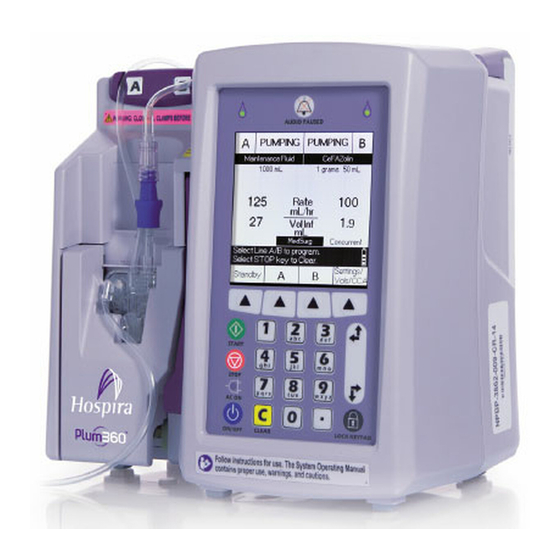
- Page 2 Compatible with Software For use with the following list numbers: 30010 30011 30012 (Including English for Canada list numbers 30010-65, 30011-65, and 30012-65) Technical Service Manual Hospira, Inc. 275 North Field Drive Lake Forest, IL 60045 USA 430-97316-001 (E, 2014-10)
- Page 3 This page intentionally left blank. Plum 360 Infuser Technical Service Manual...
- Page 4 (D, 2014-06) 430-97316-001 Changed Sections 1, 4, 5, 6, 7, 8, 9 to align content with current (E, 2014-10) infuser hardware/software. Removed Index. Updated front and back covers with current revision information and symbols. Technical Service Manual Plum 360 Infuser...
- Page 5 CHANGE HISTORY This page intentionally left blank. Plum 360 Infuser Technical Service Manual...
-
Page 6: Table Of Contents
ETHERNET SETTINGS ....1 31 1.12.8.3 HOSPIRA MEDNET SETTINGS ... 1 32 1.12.8.4 RESET NETWORK TO DEFAULT SETTINGS ..1 33 1.12.8.5... - Page 7 CE 3.0 COMMON AND PERIPHERAL INTERFACES . . . 4 23 4.2.4.2 PLUM 360 CPU MEMORY ... . . 4 24 4.2.4.3 WI FI..... 4 24 4.2.4.4...
- Page 8 ..5 47 5.5.2.4 PRIMING A RUN IN CASSETTE ASSEMBLY ..5 48 5.5.2.5 DISTAL OCCLUSION TEST SETUP ..5 51 Technical Service Manual Plum 360 Infuser...
- Page 9 ....7 15 7.2.10 FRONT ENCLOSURE COMPONENT REPLACEMENT ..7 16 Plum 360 Infuser Technical Service Manual...
- Page 10 SPECIFICATIONS ......SECTION 9 DRAWINGS ......Technical Service Manual Plum 360 Infuser...
- Page 11 Device Log Shows Software Installed Successfully ... . 1 19 Figure 1 20 Plum 360 Navigation Keys ..... . . 1 20 Figure 1 21 Preventive Maintenance Menu Selection .
- Page 12 Cleaning the Cassette Receptacle Pins and Sensors ... . 5 9 Figure 5 6 Plum 360 Infuser Labels ..... . . 5 17 Figure 5 7 Plum 360 Power Cord, Retainer, and Velcro Strap .
- Page 13 Regulator Closer ......6 18 Figure 7 1 Bottom View Plum 360 Infuser ..... 7 3 Figure 7 2 Battery Assembly .
- Page 14 Drawings ......Table 9 2 IPB for the Infuser ..... Technical Service Manual Plum 360 Infuser...
- Page 15 CONTENTS This page intentionally left blank. Plum 360 Infuser Technical Service Manual...
-
Page 16: Introduction
If a problem in device operation cannot be resolved using the information in this manual, contact Hospira (see Section 6.1). for technical assistance Note: Servicing on the Plum 360 infuser is to be performed only by trained, authorized personnel. SCOPE This manual is organized into the following sections: Section 1 Introduction... -
Page 17: Conventions
A MANDATORY ACTION SYMBOL MEANS THE INSTRUCTIONS THAT FOLLOW DESCRIBE A REQUIRED ACTION. FAILURE TO OBSERVE A MANDATORY ACTION COULD IMPACT USER OR PATIENT SAFETY. Note: A note highlights information that helps explain a concept or procedure. Plum 360 Infuser 1 - 2 Technical Service Manual... -
Page 18: Component Designators
DPM Digital pressure meter ECG Electrocardiogram EEG Electroencephalogram EEPROM Electrically erasable programmable read-only memory EMC Electromagnetic compatibility EMG Electromyogram EMI Electromagnetic interference ESD Electrostatic discharge ETO Ethylene oxide FPGA Field programmable gate array Technical Service Manual 1 - 3 Plum 360 Infuser... - Page 19 PWM Pulse width modulator RAM Random access memory rms Root-mean-square RTC Real-time clock SCC Serial communication controller SCP Serial communication port SLA Sealed lead acid SMT Surface mount technology SPI Serial peripheral interface Plum 360 Infuser 1 - 4 Technical Service Manual...
-
Page 20: User Qualification
Microsecond USER QUALIFICATION The Plum 360 infuser must be used at the direction of or under the supervision of licensed physicians or certified healthcare professionals who are trained in the use of the infuser and the administration of parenteral and enteral fluids and drugs, and whole blood or red blood cell components. -
Page 21: Electromagnetic Compatibility
SECTION 1 INTRODUCTION ELECTROMAGNETIC COMPATIBILITY The Plum 360 infuser (List Number 30010 with Module 30011 or 30012) has been tested to the requirements of IEC 60601-1-2:2007 and IEC 60601-2-24:2012. The infuser meets the EMC requirements of the Medical Device Directive 93/42/EEC with amendments by 2007/47/EC. -
Page 22: Canadian Department Of Communications Industry Canada Notice (Canada Only)
The user of the Plum infuser shall not perform any modifications to the wireless module other than the repairs described in Section 7.2.6. Unauthorized changes or modifications to the wireless system voids the user’s authority to operate the wireless system of the Plum infuser. Technical Service Manual 1 - 7 Plum 360 Infuser... -
Page 23: Unpacking
EQUIPMENT, THE INFUSER SHOULD BE OBSERVED TO VERIFY NORMAL OPERATION IN THE CONFIGURATION IN WHICH IT WILL BE USED. Note: The Plum 360 infuser does not require any special installation. The only preparation needed is for the biomedical technician to set the facility desired default settings and fully charge the battery. -
Page 24: Self Test
MECHANISM INITIALIZATION IN PROGRESS prior to the CASSETTE TEST IN PROGRESS message. 6. A message may appear. Press NEW PATIENT? [YES] 7. Press to turn off the infuser. [ON/OFF] Technical Service Manual 1 - 9 Plum 360 Infuser... -
Page 25: Figure 1 1 Plum 360 Enabled Display And Keypad
KEYPAD STOP CONNECTED p q r s t u v w x y z INDICATOR AC ON ON OFF CLEAR LOCK KEYPAD Figure 1-1. Plum 360 Enabled Display and Keypad Plum 360 Infuser 1 - 10 Technical Service Manual... -
Page 26: Connectivity Check
Note: If the wireless icon or Ethernet icon does not appear in the lower right hand corner of the display, or the green Activity Indicator LED (see Figure 1-7) on the CE module is not illuminated periodically, contact the local IT representative or Hospira. Technical Service Manual 1 - 11 Plum 360 Infuser... -
Page 27: Figure 1 5 Hospira Mednet Is Active Symbol
SECTION 1 INTRODUCTION 3. Check that the Hospira MedNet connectivity symbol is displayed above the wireless or Ethernet symbol. See Figure 1-5. Figure 1-5. Hospira MedNet is Active Symbol PUMPING Heparin 25,000 Units 250mL Dose units/kg/hr Rate mL/hr 499. Vol Inf... -
Page 28: Biomed
1.12 BIOMED 1.12 BIOMED The BIOMED mode is used by qualified, trained biomedical engineering personnel to view and/or change settings in the Plum 360 infuser. The BioMed Settings page (see Figure 1-8) contains the following menu options: - Preventive Maintenance - Section 1.12.3... -
Page 29: Figure 1 9 Plum 360 Charge Indicator Light
INDICATOR AC ON ON OFF CLEAR LOCK KEYPAD ON/OFF Decimal button Figure 1-10. Plum 360 ON/OFF Button and Decimal Key The infuser performs a system self test. Plum 360 Infuser 1 - 14 Technical Service Manual... -
Page 30: Figure 1 11 System Self Test Screen
Figure 1-11. System Self Test Screen 3. When the self test is complete, the Biomed Passcode screen appears. Passcode Enter Passcode for Biomed Passcode Use keypad then press Enter Enter Cancel Figure 1-12. Biomed Passcode Screen Technical Service Manual 1 - 15 Plum 360 Infuser... -
Page 31: Figure 1 13 Enter Passcode .963
Software Choose Request Figure 1-14. Biomed Settings Menu Note: The Software Request softkey only appears if the infuser is connected to the Hospira MedNet system. For instructions on updating the software, see Section 1.12.2. Plum 360 Infuser 1 - 16... -
Page 32: Software Updates
1.12 BIOMED 1.12.2 SOFTWARE UPDATES When new versions of the Plum software are available, Hospira notifies the Biomed technician. The Biomed technician then updates the software in the Plum infuser via the Hospira MedNet connection. To update the Plum software with the latest version: (see Section 1.12.1). -
Page 33: Figure 1 17 New Software Available Screen
Turn on the infuser and access the Biomed mode. b. Select Display Logs on the Biomed Settings screen. c. Open Device Logs (see Section 1.12.6). d. Check the device log for the entry SWInstallSuccessful (Figure 1-19). Plum 360 Infuser 1 - 18 Technical Service Manual... -
Page 34: Figure 1 19 Device Log Shows Software Installed Successfully
Additionally, the updated version number displays on the opening screen. Note: The infuser should not be placed into service if the software update has not been verified. 7. After re-booting the infuser, make sure the Hospira MedNet and Ethernet (or wireless) icons are displayed (see Section 1.11). -
Page 35: Preventive Maintenance
PREVENTIVE MAINTENANCE To set Preventive Maintenance notifications: 1. Use the navigation keys on the keypad to scroll to Preventive Maintenance in Biomed Settings and press Choose. Figure 1-20. Plum 360 Navigation Keys Biomed Settings Serial Number: 17705238 Preventive Maintenance Set Time and Date... -
Page 36: Figure 1 23 Change Battery Softkey
Figure 1-24. Clear Battery Warning Message 4. Press Yes to change the battery, and press No to retain the battery logs and return to the main menu. 5. Press Done to return to the main menu. Technical Service Manual 1 - 21 Plum 360 Infuser... -
Page 37: Set Time And Date
Note: Time zone offset is from Coordinated Universal Time UTC/GMT. Note: When the Time Zone offset is set with GMT, the time stamp in the Display Logs menu option displays the correct time of day for local time. Plum 360 Infuser 1 - 22 Technical Service Manual... -
Page 38: Manage Languages
Note: If the device is connected to Hospira MedNet, the time is automatically set and the Biomed only has to set the time zone field. If the device is not connected to Hospira MedNet, the Biomed only has to set the local time; the Time Zone field will be of no use. -
Page 39: Figure 1 29 Change Language Activate Softkey
Pending until the system reboots. After exiting the Biomed mode and powering off, the software changes to the selected language upon the next reboot for either Biomed or clinical mode. Plum 360 Infuser 1 - 24 Technical Service Manual... -
Page 40: Display Logs
AC power are removed for a short or extended amount of time. The log data is stored in non-volatile memory. For a complete list of alarm codes and error codes, see Section 6.2.1 Section 6.2.2. Technical Service Manual 1 - 25 Plum 360 Infuser... -
Page 41: Figure 1 33 Alarm And Device Logs
1. Use the navigation keys to scroll to Infuser Settings and press Choose: Biomed Settings Serial Number: 10162047 Preventive Maintenance Set Time and Date Manage Languages Display Logs Infuser Settings Manage Network Press Choose to Select Choose Figure 1-34. Infuser Settings Menu Option Plum 360 Infuser 1 - 26 Technical Service Manual... -
Page 42: Figure 1 35 Infuser Settings Screen
Default End of Infusion: Choose KVO / Rate to change Press Done to save and return KVO/Rate Done Figure 1-36. Infuser Defaults Screen 3. Select the option and change the setting. Technical Service Manual 1 - 27 Plum 360 Infuser... -
Page 43: Figure 1 37 Programming Options Screen
0.1 - 99.9 mL/hr and 100 - 999 mL/hr Allow standby Yes or No Maximum Standby Time 72 hours 24 - 72 hours in 1 hour increments Allow Delayed Start Yes or No Plum 360 Infuser 1 - 28 Technical Service Manual... -
Page 44: Manage Network
Previous Choose Screen Figure 1-39. Network Settings CE 3.0 Screen Note: The data displayed in the wireless, Ethernet, and Hospira MedNet Settings screens is sent from the CE (Connectivity Engine) as part of the communication protocol. Technical Service Manual 1 - 29... -
Page 45: Wireless Settings
IP Address: 10.22.91.167 Subnet Mask: 255.255.248.0 SSID: Hospira DHCP: Enabled Gateway: 10.22.95.250 DNS1: 10.23.127.220 DNS2: 10.23.45.220 Press Refresh to update Page Page Previous Refresh Down Screen Figure 1-41. Wireless Settings Screen Plum 360 Infuser 1 - 30 Technical Service Manual... -
Page 46: Ethernet Settings
Ethernet Settings Connection Status: Connected IP Address: 10.20.137.104 Subnet Mask: 255.255.248.0 DHCP: Enabled Gateway: 10.20.136.250 DNS1: 10.20.143.220 DNS2: 10.23.45.220 Domain: Press Refresh to update Previous Refresh Screen Figure 1-43. Ethernet Settings Screen Technical Service Manual 1 - 31 Plum 360 Infuser... -
Page 47: Hospira Mednet Settings
Reset Network to Default Settings Select Choose to view settings Shutdown Previous Choose Screen Figure 1-44. Hospira MedNet Settings Menu Option 2. Press Choose to view the current Hospira MedNet settings. Hospira MedNet Settings Hospira MedNet IP: 10.20.110.178 Hospira MedNet Mask: 255.255.248.0 SSL:... -
Page 48: Reset Network To Default Settings
Yes: Will Reset No: Cancel Figure 1-47. Reset Network Settings Screen 3. Press Yes to reset the network settings to the defaults or No to cancel and return to the previous screen. Technical Service Manual 1 - 33 Plum 360 Infuser... -
Page 49: Shutdown Ce
CE and Plum! Yes: Shuts down CE then the Plum No: Cancel Figure 1-49. Confirm CE Shutdown Warning Screen 3. Press Yes to confirm the shutdown of the entire device. Plum 360 Infuser 1 - 34 Technical Service Manual... -
Page 50: Figure 1 50 Wait For Shutdown Screen
Note: Wait at least five minutes for the CE module to power down and the microprocessor to save data before you remove the CE module. 4. Remove the CE module, if planning to replace it. For the replacement procedure, Section 7.2.6. Technical Service Manual 1 - 35 Plum 360 Infuser... - Page 51 SECTION 1 INTRODUCTION This page intentionally left blank. Plum 360 Infuser 1 - 36 Technical Service Manual...
-
Page 52: Warranty
(whether such cause be based in contract, negligence, strict liability, other tort, or otherwise) exceed the price of such product, and in no event shall Hospira be liable for incidental, consequential, or special damages or losses or for lost business, revenues, or profits. - Page 53 SECTION 2 WARRANTY This page intentionally left blank. Plum 360 Infuser 2 - 2 Technical Service Manual...
-
Page 54: System Operating Manual
Section 3 SYSTEM OPERATING MANUAL A copy of the System Operating Manual is included with every Plum 360 infuser. If a copy contact Hospira (see Section 6.1). is not available, Technical Service Manual 3 - 1 Plum 360 Infuser... - Page 55 SECTION 3 SYSTEM OPERATING MANUAL This page intentionally left blank. Plum 360 Infuser 3 - 2 Technical Service Manual...
-
Page 56: Theory Of Operation
Section 4 THEORY OF OPERATION This section describes the theory of operation for the Plum 360 Infuser. The theory of operation details the general description, electronic subsystem overview, printed wiring assemblies, LCD, and mechanical overview of the infuser. GENERAL DESCRIPTION... -
Page 57: Electronic Subsystem Overview
(SCC) channels and the serial communication port (SCP) channels. The 24 bit address bus is capable of accessing up to 16 MB of data. Plum 360 Infuser 4 - 2 Technical Service Manual... -
Page 58: System Memory Address Map
DC/AC inverter. Intensity control is achieved by superimposing a DC control signal with the feedback signal. The DC control signal is sourced by a voltage divider consisting of a digitally controlled non-volatile potentiometer and three series diodes. Technical Service Manual 4 - 3 Plum 360 Infuser... -
Page 59: Lcd Contrast Control
WDI remains either high or low for longer than the watchdog timeout period. After a reset, the software reads this memory-mapped bit to determine if the latest reset was a watchdog timeout. Plum 360 Infuser 4 - 4 Technical Service Manual... -
Page 60: Voltage Monitor Watchdog Timer
The analog inputs are selected by the channel multiplexer according to the input address (see Table 4-1). The input multiplexer is a break-before-make type to reduce input-to-input noise injection resulting from channel switching. Technical Service Manual 4 - 5 Plum 360 Infuser... -
Page 61: Figure 4 1 Serial Interface To Adc
BUZTST Buzzer test voltage LCDTST LCD contrast test voltage TUBTST CCFT intensity test voltage MI_STA Motor current A control MI_STB Motor current B control ) / 2 ref(+) ref(-) ref(-) ref(+) Plum 360 Infuser 4 - 6 Technical Service Manual... -
Page 62: Table 4 2 Keypad Map
(LEDAE*, LEDBE*). The AC power on LED indicates the status of AC power (LEDAC). A power supply AC on signal (BACON) controls the LED and is active only when AC power is connected. Technical Service Manual 4 - 7 Plum 360 Infuser... -
Page 63: Nurse Call Interface
Raw, unregulated charger voltage or battery voltage V2_7 2.7 V backup power for RTC and non-volatile SRAM Full time 5 V supply, backed up by supercap V12_0 12 V, low current supply for audio alarm Plum 360 Infuser 4 - 8 Technical Service Manual... -
Page 64: Infusion Mechanism Interface
Flag, I/O valve cam sensor D, I FLLS_A Flag, L/S valve A pin detector D, I FLLS_B Flag, L/S valve B pin detector D, I FLPLRO Flag, plunger rotation sensor D, I Technical Service Manual 4 - 9 Plum 360 Infuser... - Page 65 Motor power is directly from power supply PWA V2_5 Reference voltage for ADC and DAC A, I Legend: P = Power A = Analog D = Digital I = Input O = Output Plum 360 Infuser 4 - 10 Technical Service Manual...
-
Page 66: Power Supply Subsystem
Resistor R70 and capacitor C46 filter the voltage across R71 and feed it back to the current sense input (1.5 V threshold) of U12. The duty cycle of U12 is reduced until the excessive load is removed. Technical Service Manual 4 - 11 Plum 360 Infuser... -
Page 67: Main Regulator Fault Detection
STRTUP signal, via interrupt, to signal a user request for turning off the infuser. Figure 4-2 illustrates the system startup/shutdown sequence while battery powered. System power is always on while AC powered. Plum 360 Infuser 4 - 12 Technical Service Manual... -
Page 68: Battery Voltage Measurement
The software battery management algorithm controls the battery charger. The charging scheme is a current limit/two stage voltage limit charger. The charge current is limited to 1.3 A and the voltage is limited to either 6.74 V or 7.35 V Technical Service Manual 4 - 13 Plum 360 Infuser... -
Page 69: Battery
4.2.2.9 BATTERY The battery employed by the Plum 360 infuser is a sealed lead acid (SLA) type rated at 6 volts DC and a current capacity of at least 4.0 ampere-hours. A fully-charged, new battery provides three hours of operation at 125 mL/hr, or delivers 250 mL total volume, if pumping at a rate of 126 mL/hr or greater, whichever occurs first. -
Page 70: Infusion Mechanism Subsystem
(phases) are completed. The step-angle (the number of steps per shaft revolution) resolutions are 3.6 degrees/step (100 steps/rev) for the plunger motor, and 7.5 degrees/step (48 steps/rev) for the I/O and L/S valve motors. Technical Service Manual 4 - 15 Plum 360 Infuser... -
Page 71: Motor Position Sensors
Optical switch flag sensors are used for tracking: - Plunger motor rotational position (coupler flag) - Plunger translational (linear) position - I/O valve motor rotational position (cam flag) - L/S valve motor rotational position (cam flag) Plum 360 Infuser 4 - 16 Technical Service Manual... -
Page 72: V2_5 Reference Voltage
(proximal) or out of (distal) the cassette. Both sensors are piezoelectric crystal transmitter receiver pairs. Liquid between the transmitter and receiver will conduct the ultrasonic signal, while air will not (see Figure 4-4). Technical Service Manual 4 - 17 Plum 360 Infuser... -
Page 73: Figure 4 4 Air Sensor Block Diagram
V2_5 supply. DIARE and PXARE are used to enable the distal and proximal sensors, respectively. The detector stage consists of an emitter follower, charging a 400 microsecond time constant, refreshed every 40 microseconds (twice per VCO sweep). Plum 360 Infuser 4 - 18 Technical Service Manual... -
Page 74: Pressure Sensors
3.75 V (FROM CPU) WHEATSTONE BRIDGE REFERENCE 2.5 V DIFFERENTIAL AMPLIFIER AND OFFSET ADJUST OUTPUT PRESSURE AMPLIFIER SIGNAL OUTPUT AND FILTER (TO CPU) Figure 4-5. Pressure Sensor Excitation and Amplifier Block Diagram Technical Service Manual 4 - 19 Plum 360 Infuser... -
Page 75: Pressure Sensor Calibration
The FSR is arranged in a voltage divider configuration with a fixed resistor, followed by a comparator with hysteresis. The comparator circuits are located on the CPU PWA. The comparators are designed to trip as the FSR’s resistance falls below 120 KΩ. Plum 360 Infuser 4 - 20 Technical Service Manual... -
Page 76: Serial Eeprom
4.2.4 CONNECTIVITY ENGINE MODULE REVISION 3.0 The Connectivity Engine Module Revision 3.0 contains: • Memory to be used by the Plum 360 infuser CPU • CE 3.0 Subsystem to connect to Hospira MedNet software • Nurse Call interface (see Figure 4-6) •... - Page 77 RXD1/ LED Drivers Yellow CTS1/ Spare RTS1 RJ-11 Connector Nurse Call Nurse Call NURSE Isolation Circuit LOTSW Audio Volume BUZADJ/ Control BUZL Figure 4-7. Single Peripheral Assembly with CE 3.0 Subsystem Plum 360 Infuser 4 - 22 Technical Service Manual...
-
Page 78: Ce 3.0 Common And Peripheral Interfaces
It also contains transceivers for Ethernet. The peripheral assembly contains the connector that serves as the interface to the Plum 360 infuser CPU PWA. In addition, the peripheral assembly contains the interface for Ethernet, Wi-Fi (802.11 a/b/g/n), Nurse Call, and Volume Control. Communication with the Hospira MedNet system requires both assemblies to be present and mated. -
Page 79: Plum 360 Cpu Memory
CPU accesses via the 96-pin board to board connector interface. They are used to support the various functions on the Plum 360 infuser and are powered from a 3.3 V supply provided by the CPU PWA. The 3.3 V... -
Page 80: Usb
4.2.4.8 iMX534 APPLICATION PROCESSOR The main processor that enables communication with the Hospira MedNet system is the Freescale iMX534. It has an 800 MHz 32-bit ARM Cortex-A8 CPU with 32 KB instruction and data caches. To support the CE 3.0 functionality, the chip has interfaces for sending and receiving Wi-Fi and Ethernet data, and is powered by the Freescale MC34708 Power Management IC. -
Page 81: Peripheral Assembly
Board-to-board connection to common PWA 80 pin LSS connector Board-to-board connection to common PWA 96 pin receptacle Board-to-board connection to CPU PWA RJ-45 connector Shielded Ethernet connector RJ-12 connector Nurse Call connector Plum 360 Infuser 4 - 26 Technical Service Manual... -
Page 82: Common Pwa
Connection to peripheral assembly (CPU bus, rear panel I/O, and communication ports) 30 pin header Connection to power supply PWA 50 pin SMT Ribbon cable connection to driver PWA (infusion mechanism) Technical Service Manual 4 - 27 Plum 360 Infuser... -
Page 83: Driver Pwa
The switch PWA contains the plunger translation position sensor that is one of six position sensors in the system. The switch PWA is located at the side of the infusion mechanism sub-chassis, and connects to the driver PWA. Plum 360 Infuser 4 - 28 Technical Service Manual... -
Page 84: App Pwa
The following sections detail the cassette and the infusion mechanism assembly. Technical Service Manual 4 - 29 Plum 360 Infuser... -
Page 85: Cassette
Similarly, a second air-in-line sensor located distal to the pumping chamber initiates an audible alarm if a predetermined amount of air is detected. Plum 360 Infuser 4 - 30 Technical Service Manual... -
Page 86: Infusion Mechanism Assembly
0.33 mL of fluid per cycle. The plunger motion is synchronized to the valve motors to provide controlled fluid delivery. Figure 4-11 for infusion mechanism valve pins and sensor locations. Technical Service Manual 4 - 31 Plum 360 Infuser... -
Page 87: Motor And Valve Assemblies
Figure 4-11. infusion Mechanism Valve Pins and Sensor Locations 4.5.2.3 INLET/OUTLET VALVE SUBSYSTEM The inlet/outlet valve subsystem is similar in function and build to the A/B valve subsystem (see Section 4.5.2.2). Plum 360 Infuser 4 - 32 Technical Service Manual... -
Page 88: Plunger Drive Subsystem
During operation, if the screw/coupler flag passes through the interrupter module at the incorrect time sequence, a motor phase loss is detected. Technical Service Manual 4 - 33 Plum 360 Infuser... - Page 89 SECTION 4 THEORY OF OPERATION This page intentionally left blank. Plum 360 Infuser 4 - 34 Technical Service Manual...
-
Page 90: Maintenance And Service Tests
WARNING COULD RESULT IN ELECTRICAL SHOCK. CLEANING AND DISINFECTION The following sections describe how to clean and disinfect the Plum 360 infuser between each patient use. These instructions should also be used to prepare the infuser for storage, repair, or preventive maintenance. -
Page 91: Cleaning
CAUTION: Do not spray cleaning solutions toward any opening in the infuser. CAUTION: Use all cleaning solutions as specified by the manufacturer, to avoid infuser damage. Use only recommended cleaning solutions and follow manufacturer’s recommendations regarding dilution. Using cleaning solutions not recommended by Hospira may result in product damage. 5.2.1... -
Page 92: Cleaning Supplies
Note: Administration sets must be removed by authorized personnel and disposed of per facility policy before cleaning the infuser. Note: If the minipole is attached, see Section 7.2.12 for instructions on removing the minipole assembly. Technical Service Manual 5 - 3 Plum 360 Infuser... -
Page 93: General Cleaning Instructions
8 / surface 7 / surface 1 / surface 5 / surface 15 / surface Ensure the surfaces remain moist the entire duration of each time interval (depending on the procedure). Plum 360 Infuser 5 - 4 Technical Service Manual... -
Page 94: Cleaning Exterior Surfaces
3. Wipe bottom surface using cleaning solution and lint-free cloths or wipes. 4. Lift the infuser, wipe the surface where it was resting, and place it upright. 5. Wipe top and side surfaces using cleaning solution and lint-free cloths or wipes. Technical Service Manual 5 - 5 Plum 360 Infuser... - Page 95 5-2). Note: Do not allow fluid into any ports or vents on the CE Module. 5. Wipe areas around the power cord outlet, the power cord, and the plug, including prongs. Plum 360 Infuser 5 - 6 Technical Service Manual...
-
Page 96: Cleaning The Cassette Receptacle
For (see Figure 5-4) this reason, the cassette receptacle should only be cleaned by personnel who are aware of how the infuser operates and can take proper precautions. Technical Service Manual 5 - 7 Plum 360 Infuser... - Page 97 To clean the cassette receptacle: 1. Open the cassette door, and press the yellow-marked, door release tab as shown Figure 5-4. 2. Gently press the cassette door down until it opens completely. Plum 360 Infuser 5 - 8 Technical Service Manual...
- Page 98 Note: If the roller does not spin smoothly, replace the door (see Section 7.2.13.8). 6. Clean the door lever, and use swabs to clean the crevices around it. Note: Do not allow fluid into the internal part of the infuser. Technical Service Manual 5 - 9 Plum 360 Infuser...
-
Page 99: Cleaning The Power Cord Velcro Strap
3. When no moisture is detected, close the cassette door. Note: Allow to air dry completely before beginning disinfection. Note: After the cassette door receptacle is dry, close the cassette door to avoid damage when moving the infuser. Plum 360 Infuser 5 - 10 Technical Service Manual... -
Page 100: Disinfection
Do not exceed 1 part bleach in 10 Household Bleach parts water (8.25% concentration) Note: At the time of publication, Hospira recommends only the disinfecting solutions in Table 5-4. For updated listings of approved disinfectants, visit www.hospiraparts.com. 5.3.2 DISINFECTING SUPPLIES... -
Page 101: General Disinfection Instructions
Table 5-6. Minimum Time Intervals for Disinfecting Disinfectant in Contact with Infuser Rinsing with Water 15 minutes 3 minutes Ensure the surfaces remain moist the entire duration of each time interval (depending on the procedure). Plum 360 Infuser 5 - 12 Technical Service Manual... -
Page 102: Disinfecting Exterior Surfaces
2. Carefully swab the pins, sensors, and surrounding areas without tilting the infuser (see Figure 5-5). back 3. Use a swab dipped in 70% isopropyl alcohol to disinfect the air-in-line detectors and remove residue from cleaning. Technical Service Manual 5 - 13 Plum 360 Infuser... -
Page 103: Disinfecting The Power Cord Velcro Strap
3. When no moisture is detected, reattach the power cord Velcro strap. 4. Return the infuser to service. Note: Make sure the power cord and plug are completely dry before plugging the infuser into AC (mains) power. Plum 360 Infuser 5 - 14 Technical Service Manual... -
Page 104: Preventive Maintenance
5.4 PREVENTIVE MAINTENANCE PREVENTIVE MAINTENANCE Hospira requires that preventive maintenance be performed at least once every 12 months. Replace components as required by visual inspection and test results. Complete the Preventive Maintenance Checklist in Section 5.4.13. Note: Perform the Performance Verification Test along with the visual inspections as part of the preventive maintenance process at least once every12 months. -
Page 105: Labels Inspection
- Front Label - - Tubing Guide Consult Labels (A/B Labels) Accompanying Documents - (lower under keypad) 3. Inspect the labels for legibility and peeling. To replace a label, contact Hospira. Plum 360 Infuser 5 - 16 Technical Service Manual... - Page 106 MAC ADDRESS LABELS (ETHERNET AND WIRELESS) BRAND LABEL (PAD-PRINTED) PRODUCT I.D. LABEL (DRIVER) FOLLOW SERVICE POWER CORD INSTRUCTIONS REVISION LEVEL LABEL FOR USE LABEL LABEL (DRIVER) Figure 5-6. Plum 360 Infuser Labels Technical Service Manual 5 - 17 Plum 360 Infuser...
-
Page 107: Ac Power Cord, Retainer, And Velcro Strap Inspection
JACK SCREW STEP 5 6-32 x 5/8 PAN HEAD SCREW AC POWER CORD STEP 4 RETAINER AC POWER CORD POWER CORD LABEL Figure 5-7. Plum 360 Power Cord, Retainer, and Velcro Strap Plum 360 Infuser 5 - 18 Technical Service Manual... -
Page 108: Front Enclosure, Rear Enclosure, Cassette Door, And Door Lever Inspection And Test
If the door does not open smoothly, check for debris or dried fluid buildup. Clean the infusion mechanism as described in Section 5.2. 2. Move the door lever to the CLOSED position. Confirm smooth operation as described in Step 1. Technical Service Manual 5 - 19 Plum 360 Infuser... -
Page 109: Door Roller Inspection And Test
7.2.13.8. smoothly, replace the door as described in 4. Confirm that the retaining ring, which secures the roller wheel to the pin, is seated properly, and the pin is not bent. Plum 360 Infuser 5 - 20 Technical Service Manual... -
Page 110: Fluid Shield Inspection
Figure 5-9. Door Roller Inspection 5.4.5 FLUID SHIELD INSPECTION Visually inspect the Plum 360 infuser fluid shield at least once every 12 months. Equipment required for the fluid shield inspection is a 0.025 inch (0.65 mm) feeler gauge (plastic or metal),... - Page 111 If the diaphragm is torn, cracked, or missing, contact Hospira for repair. CLOSE LEVER WHEN Figure 5-10. Releasing the Cassette Door FEELER GAUGE Figure 5-11. Inspecting the Fluid Shield with Feeler Gauge Plum 360 Infuser 5 - 22 Technical Service Manual...
-
Page 112: Distal Pressure Pin Inspection
2. Release the door so that it lays flat. Press the door release tab to the right and open the cassette door all the way (see Figure 5-10). 3. Inspect the distal pressure pin to determine that it is not damaged or broken. Technical Service Manual 5 - 23 Plum 360 Infuser... -
Page 113: Proximal Pressure Pin Inspection
2. Release the door so that it lays flat. Press the door release tab to the right and open the cassette door all the way (see Figure 5-10). 3. Inspect the pin to determine that it is not damaged or broken. Plum 360 Infuser 5 - 24 Technical Service Manual... -
Page 114: Rubber Foot Pad Inspection
5-15, and proceed as follows: 1. Inspect for missing or loose rubber foot pads, and rubber foot pads that are starting to peel away from the enclosure. Replace or install as described in Section 7.2.3. Technical Service Manual 5 - 25 Plum 360 Infuser... -
Page 115: Pole Clamp Inspection And Test
SECTION 5 MAINTENANCE AND SERVICE TESTS RUBBER FOOT PAD (5) Figure 5-15. Rubber Foot Pads on Plum 360 Infuser 5.4.9 POLE CLAMP INSPECTION AND TEST Visually inspect and test the pole clamp at least once every 12 months. To inspect the pole clamp, see... - Page 116 5.4 PREVENTIVE MAINTENANCE CHECK FOR SECURE ATTACHMENT TO REAR ENCLOSURE Figure 5-16. Pole Clamp and Extrusion on Plum 360 Infuser RUBBER PAD THREADED INTERFACE SHAFT TIP Figure 5-17. Pole Clamp Assembly Technical Service Manual 5 - 27 Plum 360 Infuser...
-
Page 117: Battery Replacement
Contact Hospira to obtain a replacement battery. If spare parts, other than Hospira approved spare parts, are used for battery replacement, the warranty on the Plum 360 infuser shall be void. Note: The battery compartment must be visually inspected once every 12 months. - Page 118 15. Press to turn off the infuser. [ON/OFF] BATTERY WITH WIRE HARNESS ASSEMBLY BATTERY DOOR PAD SOFT PUSH ON RETAINING RING BATTERY DOOR SLOTTED HEX HEAD SCREW Figure 5-18. Removing the Battery Technical Service Manual 5 - 29 Plum 360 Infuser...
-
Page 119: Keypad Inspection
STOP CONNECTED p q r s t u v w x y z INDICATOR AC ON ON OFF CLEAR LOCK KEYPAD Figure 5-19. Plum 360 Infuser Keypad Plum 360 Infuser 5 - 30 Technical Service Manual... -
Page 120: Display And Indicators Inspection
(see Section 7.2.13.5). 8. Observe the display area. Confirm that the display is clear and readable. (see Section 7.2.13.2). 9. If any of the LEDs are not operating, replace the keypad Technical Service Manual 5 - 31 Plum 360 Infuser... - Page 121 KEYPAD STOP CONNECTED p q r s t u v w x y z INDICATOR AC ON ON OFF CLEAR LOCK KEYPAD Figure 5-20. Plum 360 Infuser Display and Indicators Plum 360 Infuser 5 - 32 Technical Service Manual...
-
Page 122: Preventive Maintenance Checklist
PASS / FAIL Delivery Accuracy Test PASS / FAIL PASS / FAIL Nurse Call Test PASS / FAIL Electrical Safety Test YES / NO Battery Replaced? ECHNICIAN NFUSER Signature: Model: Date: Serial Number: Technical Service Manual 5 - 33 Plum 360 Infuser... -
Page 123: Performance Verification Test
Section 5.5.12, Distal Air-In-Line Test Section 5.5.13, Distal Occlusion Test Section 5.5.14, Delivery Accuracy Test Section 5.5.15, Nurse Call Test Section 5.5.16, Electrical Safety Test Section 5.5.17, End of the PVT Plum 360 Infuser 5 - 34 Technical Service Manual... -
Page 124: Pvt Equipment List
Proximal Air-in-Line test, a Distal Air-in-Line Test Setup Distal that is used only for the Distal Air-in-Line test, and a Occlusion Test Setup, which is a modification of the Basic test setup. Technical Service Manual 5 - 35 Plum 360 Infuser... -
Page 125: Basic Test Setup
STOP p q r s t u v w x y z AC ON ON OFF CLEAR LOCK KEYPAD Figure 5-21. Basic Test Setup Plum 360 Infuser 5 - 36 Technical Service Manual... - Page 126 PlumSet with liquid (prime it), eliminating all air, and then load the cassette into the infuser. 1. Place the infuser on a bench or attach it to an IV pole. Technical Service Manual 5 - 37 Plum 360 Infuser...
- Page 127 Note: Do not position the container above the infuser while inserting the piercing pin. Figure 5-24. Inserting the Piercing Pin 5. Suspend the container on an IV pole. 6. Check for leaks. If any part of the container is leaking, replace it. Plum 360 Infuser 5 - 38 Technical Service Manual...
- Page 128 10. Tap and clear air from the cassette, Y-site, and tubing to remove all air from the remainder of the administration set (see Figure 5-28). Figure 5-28. Removing Air from the Administration Set Technical Service Manual 5 - 39 Plum 360 Infuser...
- Page 129 1. Lift the lever to open the cassette door (see Figure 5-30). Figure 5-30. Opening the Cassette Door 2. Grasp the cassette by the finger grip (see Figure 5-31). FINGER GRIP Figure 5-31. Cassette Finger Grip Plum 360 Infuser 5 - 40 Technical Service Manual...
- Page 130 7. Ensure that the score mark on the drip chamber is 12 to 24 inches higher than the cassette. 8. Place the distal end of the tubing in the collection container. Go to Section 5.5.2.1.4, to attach and prime the secondary line. Technical Service Manual 5 - 41 Plum 360 Infuser...
- Page 131 4. Squeeze the drip chamber to fill it about 1/3 full or to the score mark (see Figure 5-34). Do not completely fill the drip chamber. Figure 5-34. Squeezing the Drip Chamber Plum 360 Infuser 5 - 42 Technical Service Manual...
- Page 132 Clave. Move the Option-Lok collar over the Clave and twist (see Figure 5-37). clockwise to secure the line to the port OPTION-LOK COLLAR CLAVE SECONDARY PORT Figure 5-37. Option-Lok Collar and Clave Secondary Port Technical Service Manual 5 - 43 Plum 360 Infuser...
- Page 133 8. Arrange the fluid container so that the score mark on the drip chamber is 12 to 24 inches higher than the cassette. Note: The secondary container does not need to be higher than the primary container for accurate delivery of a piggyback infusion. Plum 360 Infuser 5 - 44 Technical Service Manual...
- Page 134 STOP p q r s t u v w x y z AC ON ON OFF CLEAR LOCK KEYPAD Figure 5-39. Complete Basic Test Setup Technical Service Manual 5 - 45 Plum 360 Infuser...
-
Page 135: Proximal Air In Line Test Setup
Figure 5-40. Preparing the Proximal Run-In Cassette 2. Using the permanent marker, write “Proximal” and the date on the drip chamber. 3. Follow the instructions for priming a run-in cassette assembly in Section 5.5.2.4. Plum 360 Infuser 5 - 46 Technical Service Manual... -
Page 136: Distal Air In Line Test Setup
Figure 5-41. Preparing the Distal Run-In Cassette 2. Using the permanent marker, write “Distal” and the date on the drip chamber. Section 5.5.2.4. 3. Follow the instructions for priming a run-in cassette assembly in Technical Service Manual 5 - 47 Plum 360 Infuser... -
Page 137: Priming A Run In Cassette Assembly
4. Turn on the infuser. During the self test, the infuser may issue a cassette test failure alarm. 5. Press and hold [BACKPRIME] to pump water from the drip chamber into the proximal lines and cassette. Plum 360 Infuser 5 - 48 Technical Service Manual... - Page 138 If there is any leakage, replace the run-in cassette. 4. Keeping the cassette upright, remove the white cap. 5. Pull out the flow regulator (see Figure 5-43). Figure 5-43. Pulling Out the Flow Regulator Technical Service Manual 5 - 49 Plum 360 Infuser...
- Page 139 8. Release the pumping chamber and flow regulator. 9. Repeat Steps 5 through 8 until all distal air is pumped out of the tubing. 10. Replace the cap. The run-in cassette is now ready for use. Plum 360 Infuser 5 - 50 Technical Service Manual...
-
Page 140: Distal Occlusion Test Setup
• Required equipment as listed for the Basic test setup in Section 5.5.2.1. • Three-way stopcock • Digital Pressure Meter (DPM) • Cloth or paper towel to catch drips. (Small amounts of water may be released from the stopcock during testing.) Technical Service Manual 5 - 51 Plum 360 Infuser... - Page 141 2. Attach the pressure sensor connector on the DPM to a compatible port (male or (see Figure 5-48). female) on the three-way stopcock 3-WAY STOPCOCK PORT DPM CONNECTOR Figure 5-48. Attaching the Three-Way Stopcock to the DPM Plum 360 Infuser 5 - 52 Technical Service Manual...
- Page 142 AC ON ON OFF CLEAR LOCK KEYPAD UNIVERSAL PRESSUREMETER 0.00 0 to 12” cmOFHO INCHESOFHO mmHg -13.5TO15 -13.5TO75 PRESSUREINPUT Figure 5-50. DPM Connector Height Technical Service Manual 5 - 53 Plum 360 Infuser...
-
Page 143: Self Test
[ENTER]. 4. After the cassette test is complete, verify that CASSETTE TEST FAILURE is flashing on the display and that the alarm sounds. 5. Open the door and remove the cassette. Plum 360 Infuser 5 - 54 Technical Service Manual... -
Page 144: Unrestricted Flow Test
1. While the infuser displays the delivery screen, press [A] to select Line A. 2. Verify that the PROGRAM screen is displayed. Enter a rate of 23 mL/hr. Press (C) to clear the value. Technical Service Manual 5 - 55 Plum 360 Infuser... - Page 145 . Highlight VOLUME INFUSED and press [CHOOSE]. 17. Press [SETTINGS/VOLS/CCA] 18. Press the [CLEAR A]. Line A volume changes to 0 mL and the display returns to the previous screen. Plum 360 Infuser 5 - 56 Technical Service Manual...
-
Page 146: Locking And Unlocking The Keypad Test
Cancel Figure 5-51. Passcode to Lock Keypad To unlock the keypad: 1. Press any key except [STOP]. 2. When the Passcode dialog box appears, enter the passcode .963, and press Enter. Technical Service Manual 5 - 57 Plum 360 Infuser... -
Page 147: Alarm Loudness Test
5. Verify that fluid is pumping; the message PUMPING is displayed in the Line A status bar, and the LED above Line A flashes. 6. Verify that the alarm sounds and the alarm message displays. Plum 360 Infuser 5 - 58 Technical Service Manual... -
Page 148: Proximal Occlusion Test
5. Press [AUDIO PAUSED] and verify that the alarm stops while the message on the display continues to flash. 6. Unclamp the proximal line and press [START]. Verify that pumping resumes. 7. Press [STOP]. 8. Open the cassette door and remove the cassette. Technical Service Manual 5 - 59 Plum 360 Infuser... -
Page 149: Proximal Air In Line Test
6. Before 1 mL of fluid is delivered, verify that pumping stops, the alarm sounds and the alarm message is flashing on the display. 7. Open the cassette door and remove the test cassette. Plum 360 Infuser 5 - 60 Technical Service Manual... -
Page 150: Distal Occlusion Test
12. Verify that the distal pressure limit is set at 6 psi. If the pressure limit is not 6 psi, highlight the Distal Pressure Limit and enter 6. 13. Press [DONE]. 14. Press [PREVIOUS SCREEN]. Technical Service Manual 5 - 61 Plum 360 Infuser... - Page 151 NEW PATIENT? prompt. 19. Press [SETTINGS/VOLS/CCA] to select the SETTINGS/VOLS/CCA screen. 20. Select PRESSURE and press [CHOOSE]. 21. Select Distal Pressure Limit. Enter 10 psi, and press [DONE]. 22. Press [PREVIOUS SCREEN]. Plum 360 Infuser 5 - 62 Technical Service Manual...
- Page 152 28. Open and close the cassette door to clear the alarm. 29. Turn off the Infuser. 30. Remove the distal tubing from the three-way stopcock and turn off the DPM. Technical Service Manual 5 - 63 Plum 360 Infuser...
-
Page 153: Delivery Accuracy Test
AC ON ON OFF CLEAR LOCK KEYPAD 25 mL GRADUATED CYLINDER Figure 5-59. Delivery Accuracy Test Setup 2. Turn on the infuser. Plum 360 Infuser 5 - 64 Technical Service Manual... -
Page 154: Nurse Call Test
To perform the nurse call test, proceed as follows: 1. Attach the 2-prong lead on the nurse call test cable to the ports on the DMM that are marked for measuring resistance. Technical Service Manual 5 - 65 Plum 360 Infuser... - Page 155 DMM (approximately 1 Ω on a scale of 0 to 100 Ω). If the short circuit appears, the test is successful. 8. Press [STOP], and turn off the infuser. Plum 360 Infuser 5 - 66 Technical Service Manual...
-
Page 156: Electrical Safety Test
Earth leakage current (Normal Closed Normal or Earth 500 µA Condition) Reversed Earth leakage current (Single Fault Open Normal or Earth 1000 µA Condition) Reversed Chassis ground resistance (with cord connected) 0.2 Ω Technical Service Manual 5 - 67 Plum 360 Infuser... -
Page 157: End Of The Pvt
[ENTER]. 3. In response to the NEW PATIENT? prompt, press [YES]. 4. Remove the cassette and close the cassette door. 5. Turn off the infuser. 6. Return the infuser to service. Plum 360 Infuser 5 - 68 Technical Service Manual... -
Page 158: Troubleshooting
For technical assistance, product return authorization, and to order parts, accessories, or manuals from outside the United States, contact the nearest Hospira sales office. ALARM MESSAGES AND ALARM CODES Under most alarm conditions the infuser ceases normal operation, generates an audible alarm, and displays an alarm message or alarm code on the LCD screen. -
Page 159: Operational Alarm Messages And Codes
[CANCEL] softkey. and both lines are delivering by pressing the STOP hardkey, but has not selected a line (A, B, or A&B) or selected Cancel to complete the action. Plum 360 Infuser 6 - 2 Technical Service Manual... - Page 160 Press any hardkey except N101 Start or clear lines. minutes when both lines [AUDIO PAUSED]. have been stopped by the user and not cleared or restarted. Note: Will reassert if the condition persists. Technical Service Manual 6 - 3 Plum 360 Infuser...
- Page 161 CCA! the line was programmed or open the cassette door. Press STOP key under a different CCA than the CCA currently used; and Line B has a concurrent delivery was programmed. Plum 360 Infuser 6 - 4 Technical Service Manual...
- Page 162 N185 A Startup! Open/close on Line A during the cassette Either backprime or open door or Backprime integrity test: (peak detection and close the cassette algorithm door. Check the syringe size. Technical Service Manual 6 - 5 Plum 360 Infuser...
- Page 163 Line B (peak detection for kinks and correct any algorithm) during delivery found. Restart Line B. Note: The alarm can also be cleared by clearing the confirmed program or opening the cassette door. Plum 360 Infuser 6 - 6 Technical Service Manual...
- Page 164 Distal AIR! A single air bolus is detected Open the cassette door. N234 Disconnect/reprime. at the distal sensor that Clear programs. Press START. exceeds the air detection threshold. Technical Service Manual 6 - 7 Plum 360 Infuser...
- Page 165 1. Remove infusion N255 mechanism 2. Remove fluid shield 3. Visually inspect regulator closer 4. Verify regulator closer is completely engaged 5. Test If unrestricted flow persists, replace the infusion mechanism Plum 360 Infuser 6 - 8 Technical Service Manual...
- Page 166 Other hardware failure causing excessive current Replace CPU PWA. draw. (see Section 7.2.13.4) Replace infusion mechanism assembly. (see Section 7.2.13.6) Reset time and date, if necessary. (see Section 1.12.4) Technical Service Manual 6 - 9 Plum 360 Infuser...
-
Page 167: Table 6 2 Alarm Codes Requiring Technical Service
AC power and placing it into Standby mode (see the Plum 360 Infuser Operating Manual). If the E321 error code does not reappear after the charging cycle, the... - Page 168 Reset time and date, if necessary. (see Section 1.12.4) Power Off then On. Display Controller IC error. Power off the infuser. E342 Replace pump if Replace CPU PWA. alarm continues. (see Section 7.2.13.4) Technical Service Manual 6 - 11 Plum 360 Infuser...
- Page 169 (see Section 7.2.13.4) Power Off then On. Generic plunger motor error E380 Replace pump if Replace infusion mechanism alarm continues. assembly. (see Section 7.2.13.6) Reset time and date, if necessary. (see Section 1.12.4) Plum 360 Infuser 6 - 12 Technical Service Manual...
- Page 170 Reset time and date (see Section 1.12.4) E439 Power Off then On. Any key is held or activated for Power off the infuser. Replace pump if at least 2 consecutive minutes. alarm continues. Technical Service Manual 6 - 13 Plum 360 Infuser...
- Page 171 (see Section 7.2.13.4) Reset time and date, if necessary. (see Section 1.12.4) Power Off then On. Volume infused and program Power off the infuser E451 Replace pump if delivery rate mismatch alarm continues. Plum 360 Infuser 6 - 14 Technical Service Manual...
-
Page 172: Troubleshooting Procedures
E431 E447 Note: Some alarm codes include sub-ID codes. These sub-ID codes are intended for Hospira internal use only, and should be included when contacting Hospira. TROUBLESHOOTING PROCEDURES This section details recommended procedures for problems not associated with alarms requiring technical service. -
Page 173: Table 6 3 Troubleshooting With The Pvt
Replace infusion mechanism assembly (see Section 7.2.13.6) Defective special cassette Replace special cassette Proximal Air-in-Line Test (Section 5.5.11) Dirty sensors Clean sensors Defective APP PWA Replace infusion mechanism assembly (see Section 7.2.13.6) Plum 360 Infuser 6 - 16 Technical Service Manual... - Page 174 Damaged or faulty cassette Replace cassette Defective infusion mechanism Replace infusion mechanism assembly assembly (see Section 7.2.13.6) Defective AC power cord Replace AC power cord Electrical Safety Test (Section 5.5.16) (see Section 7.2.5) Technical Service Manual 6 - 17 Plum 360 Infuser...
-
Page 175: Unrestricted Flow
4. If the regulator closer is completely seated, reassemble the device and perform the PVT in Section 5.5. Regulator closer not seated correctly Regulator closer seated correctly Figure 6-1. Regulator Closer Plum 360 Infuser 6 - 18 Technical Service Manual... -
Page 176: Resetting The Network Settings To Factory Defaults
Note: The device will internally network reset. It may take up to five minutes. 9. Verify that the infuser network is now set to the factory defaults, and proceed (see Table 1-2). to a normal network configuration of the device Technical Service Manual 6 - 19 Plum 360 Infuser... -
Page 177: Resetting The Infuser Settings To Factory Defaults
Note: The device will internally reset. It may take up to five minutes. Note: Verify that the infuser is now set to the factory defaults, and proceed to a normal configuration of the device. Plum 360 Infuser 6 - 20 Technical Service Manual... -
Page 178: Replaceable Parts And Repairs
BEFORE PERFORMING REPLACEMENT PROCEDURES. CAUTION: Use proper ESD grounding techniques when handling components. Wear an antistatic wrist strap and use an ESD-protected workstation. Store PWAs in antistatic bags before placing on any surface. Technical Service Manual 7 - 1 Plum 360 Infuser... -
Page 179: Required Tools And Materials
Replacement of a rubber foot pad is routine maintenance and no verification procedure is normally required. However, if there is a possibility the infuser may have been damaged during these procedures, perform the PVT in Section 5.5. Plum 360 Infuser 7 - 2 Technical Service Manual... -
Page 180: Battery, Wire Harness, Door, And Door Pad Replacement
Section 5.4.10. Use only Hospira-approved replacement batteries. Note: Contact Hospira to obtain a replacement battery. If spare parts, other than Hospira approved spare parts, are used for battery replacement, the warranty on the Plum 360 Infuser shall be void. WARNING: DISCONNECT THE INFUSER FROM AC POWER PRIOR TO OPENING THE THE DEVICE AND CHANGING THE BATTERY. - Page 181 10. Replace the battery door using the screw that was removed in step 3. 11. Press [ON/OFF] with the infuser disconnected from AC power, and verify the front panel battery symbol illuminates. Plum 360 Infuser 7 - 4 Technical Service Manual...
- Page 182 PVT in Section 5.5. BATTERY WITH WIRE HARNESS ASSEMBLY BATTERY DOOR PAD SOFT PUSH ON RETAINING RING BATTERY DOOR SLOTTED HEX HEAD SCREW Figure 7-2. Battery Assembly Technical Service Manual 7 - 5 Plum 360 Infuser...
-
Page 183: Ac Power Cord, Retainer, And Velcro Strap Replacement
Replacement of the AC power cord, retainer, and Velcro strap is routine maintenance and no verification procedure is normally required. However, if there is a possibility the infuser may have been damaged during the procedure, perform the PVT in Section 5.5. Plum 360 Infuser 7 - 6 Technical Service Manual... -
Page 184: Ce Module Replacement
CE instructions in Section 1.12.8.5. Note: After disconnecting from AC power, wait at least five minutes for the CE to power down and the microprocessor to save data, then proceed to step 2. Technical Service Manual 7 - 7 Plum 360 Infuser... - Page 185 10. Perform the connectivity check in 11. Perform the PVT in Section 5.5 to verify successful CE module replacement. CE MODULE 4-40 X 5/8 PAN HEAD SCREW WITH WASHER (2) Figure 7-4. CE Module Plum 360 Infuser 7 - 8 Technical Service Manual...
- Page 186 LOWER EMI NUT (2) SPRING SHIELD 4-40 x 5/8 #4 FLAT TORX KNOB WASHER, SCREW (4) COVER CE MODULE BLACK COVER ROUND SEAL, PURPLE I/O COVER COVER Figure 7-5. CE Module Technical Service Manual 7 - 9 Plum 360 Infuser...
-
Page 187: Ce Module Component Replacement
EQUIPOTENTIAL TERMINAL NURSE CALL INTERFACE PORT USB COVER CE 3.0 MODULE AC POWER CORD Figure 7-6. Rear View ANTENNA ANTENNA COVER GASKET ANTENNA COVER CE MODULE HOUSING Figure 7-7. Antenna PWA Plum 360 Infuser 7 - 10 Technical Service Manual... -
Page 188: Volume Control Knob Replacement
7.2.4. 3. Carefully set the infuser face down. 4. Remove the CE module as described in Section 7.2.6. 5. Remove the antenna cover with a small screwdriver starting on the bottom. Technical Service Manual 7 - 11 Plum 360 Infuser... -
Page 189: Ce Module Cover Replacement
9. Remove the screws that secure the peripheral assembly to the CE module cover and EMI shield. 10. Note the position of the two hex nuts installed in the PWA mounting brackets located on the CE module cover. Retain the nuts for reassembly. Plum 360 Infuser 7 - 12 Technical Service Manual... -
Page 190: Separating The Front Enclosure, Rear Enclosure, And Main Chassis
9. Using the Phillips screwdriver, remove the screws in the infuser handle. 10. Using the flat blade screwdriver, press the flex tabs (see Figure 7-1) while lifting up the front enclosure, and remove the enclosure. Technical Service Manual 7 - 13 Plum 360 Infuser... - Page 191 POWER CORD 4-40 X 7/16 RETAINER SCREW JACK EQUIPOTENTIAL TERMINAL 6-32 X 3 1/4 MAIN PHILLIPS CHASIS SCREW (2) FRONT ENCLOSURE Figure 7-8. Separating the Front Enclosure, Main Chassis, and Rear Enclosure Plum 360 Infuser 7 - 14 Technical Service Manual...
-
Page 192: Front Enclosure, Rear Enclosure, Or Main Chassis Replacement
9. Reinstall the battery and connect the infuser to AC power. 10. Perform the PVT in Section 5.5 to verify successful front enclosure, rear enclosure, or main chassis replacement. Technical Service Manual 7 - 15 Plum 360 Infuser... -
Page 193: Front Enclosure Component Replacement
6. Join the front enclosure, rear enclosure, and main chassis in the exact reverse order of separation. 7. Reinstall the battery and connect the infuser to AC power. 8. Perform the PVT in Section 5.5 to verify successful front/rear enclosure gasket replacement. Plum 360 Infuser 7 - 16 Technical Service Manual... - Page 194 7.2 REPLACEMENT PROCEDURES FRONT ENCLOSURE 4-40 X 1/4 PHILLIPS SCREW (2) PROXIMAL TUBING HOLDER FLUID SHIELD GASKET GASKET DISPLAY SEAL GASKET Figure 7-9. Front Enclosure Gaskets Technical Service Manual 7 - 17 Plum 360 Infuser...
-
Page 195: Rear Enclosure Component Replacement
ENCLOSURE ASSEMBLY HANDLE BRACKET POLE CLAMP BRACKET 10-32 X 1/2 ALLEN HEAD SCREW, BLACK (2) REAR ENCLOSURE INSULATOR FRONT/REAR ENCLOSURE GASKET FOOT (2) POWER SUPPLY GASKET Figure 7-10. Rear Enclosure Components Plum 360 Infuser 7 - 18 Technical Service Manual... -
Page 196: Pole Clamp Assembly, Pole Clamp Bracket, Handle Bracket, And Insulator Replacement
8. Join the front enclosure, rear enclosure, and main chassis in the exact reverse order of separation. 9. Reinstall the battery and connect the infuser to AC power. 10. Perform the PVT in Section 5.5 to verify successful pole clamp replacement. Technical Service Manual 7 - 19 Plum 360 Infuser... -
Page 197: Pole Clamp Shaft/Knob Assembly And Shaft Tip Replacement
2. Remove the battery as described in 3. Separate the front enclosure, rear enclosure, and main chassis as described Section 7.2.8. 4. Remove the rear enclosure gasket from the rear enclosure. Remove the power supply gasket. Plum 360 Infuser 7 - 20 Technical Service Manual... -
Page 198: Minipole Assembly Replacement
Replacement of the minipole assembly is routine maintenance and no verification procedure is normally required. However, if there is a possibility the infuser may have Section 5.5. been damaged during the procedure perform the PVT as described in Technical Service Manual 7 - 21 Plum 360 Infuser... - Page 199 SECTION 7 REPLACEABLE PARTS AND REPAIRS CLUTCH HOUSING CLUTCH SPRING BAG HANGER POLE CLAMP EXTRUSION HAIRPIN CLIP Figure 7-11. Minipole Assembly Plum 360 Infuser 7 - 22 Technical Service Manual...
-
Page 200: Main Chassis Assembly Component Replacement
SCREW, 4-40 x 1/4 HEX HEAD SLOTTED, WITH WASHER MECHANISM CHASSIS BUMPER CPU/DRIVER CABLE MOTOR POWER 6-32 x 3/8 CABLE HEX HEAD SCREW WITH WASHER MECHANISM ASSEMBLY Figure 7-12. Main Chassis Assembly Components Technical Service Manual 7 - 23 Plum 360 Infuser... -
Page 201: Power Supply Pwa Replacement
8. Join the front enclosure, rear enclosure, and main chassis in the exact reverse order of separation. 9. Reinstall the battery and connect the infuser to AC power. Section 5.5 10. Perform the PVT in to verify successful power supply PWA replacement. Plum 360 Infuser 7 - 24 Technical Service Manual... -
Page 202: Keypad Replacement
10. Join the front enclosure, rear enclosure, and main chassis in the exact reverse order of separation. 11. Reinstall the battery and connect the infuser to AC power. 12. Perform the PVT in Section 5.5 to verify successful keypad replacement. Technical Service Manual 7 - 25 Plum 360 Infuser... -
Page 203: Display Assembly Replacement
7. Join the front enclosure, rear enclosure, and main chassis in the exact reverse order of separation. 8. Reinstall the battery and connect the infuser to AC power. 9. Perform the PVT in Section 5.5 to verify successful display assembly replacement. Plum 360 Infuser 7 - 26 Technical Service Manual... - Page 204 .20 X .18 X 7.15 LG DISPLAY CONDUCTIVE GASKET CONDUCTIVE 0.20 X 0.18 X 1.65 LG (3) GASKET .20 X .28 X 3.60 LG KEYPAD Figure 7-13. Keypad, Display, CPU PWA, and Piezo Alarm Technical Service Manual 7 - 27 Plum 360 Infuser...
-
Page 205: Cpu Pwa Replacement
Note: The cable’s black or red edge (pin 1) should be pointed up. Figure 7-14. Front and Rear View of CPU/Driver Cable Routed Through Main Chassis Plum 360 Infuser 7 - 28 Technical Service Manual... - Page 206 Receptacle pins Figure 7-17. Male Receptacle Header Socket on the CPU PWA Note: Verify that the pins inside the male receptacle socket housing on the CPU PWA are not damaged or bent. Technical Service Manual 7 - 29 Plum 360 Infuser...
- Page 207 Figure 7-19. Side View of the CPU/Driver Cable Female Connector Firmly Seated and Locked to the CPU PWA Male Connector 13. Install the replacement CPU PWA. 14. Reinstall the display assembly. Plum 360 Infuser 7 - 30 Technical Service Manual...
- Page 208 Figure 7-21. J11 Connector on the Infusion Mechanism Driver PWA Connector is seated Locking pin is and straight firmly locked in place Infusion mechanism Figure 7-22. CPU/Driver Cable Connected to the Infusion Mechanism Driver PWA Technical Service Manual 7 - 31 Plum 360 Infuser...
- Page 209 Figure 7-24. Power Cable and Battery Cable Tie-wrapped 22. Connect the Piezo alarm cable. 23. Reinstall the power supply and display in the exact reverse order. 24. Install the front and rear enclosures. Plum 360 Infuser 7 - 32 Technical Service Manual...
- Page 210 27. Perform the PVT in to verify successful CPU PWA replacement. MAIN CHASIS 4-40 x 3/16 SLOTTED HEX HEAD SCREW WITH WASHER (2) CPU INSULATOR CPU PWA Figure 7-25. CPU PWA Replacement Assembly Technical Service Manual 7 - 33 Plum 360 Infuser...
-
Page 211: Piezo Alarm Assembly Replacement
9. Join the front enclosure, rear enclosure, and main chassis in the exact reverse order of separation. 10. Reinstall the battery and connect the infuser to AC power. 11. Perform the PVT in Section 5.5 to verify successful piezo alarm assembly replacement. Plum 360 Infuser 7 - 34 Technical Service Manual... -
Page 212: Infusion Mechanism Assembly Replacement
10. Join the front enclosure, rear enclosure, and main chassis in the exact reverse order of separation. 11. Reinstall the battery and connect the infuser to AC power. Section 5.5 12. Perform the PVT in to verify successful infusion mechanism assembly replacement. Technical Service Manual 7 - 35 Plum 360 Infuser... - Page 213 SCREW, 4-40 x 1/4 HEX HEAD MAIN CHASSIS SLOTTED, WITH WASHER MECHANISM CHASSIS BUMPER CPU/DRIVER CABLE MOTOR POWER 6-32 x 3/8 CABLE HEX HEAD SCREW WITH WASHER MECHANISM ASSEMBLY Figure 7-26. Infusion Mechanism Assembly Replacement Plum 360 Infuser 7 - 36 Technical Service Manual...
-
Page 214: Infusion Mechanism Chassis Gasket Tape Installation
Note: Installation of gasket tape to cover the opening on the infusion mechanism chassis helps protect the Switch PWA from being exposed to fluid ingress. The required tool for this procedure is the Hospira alignment fixture (P/N 519-97225-001). The replacement part for this procedure is:... -
Page 215: Cassette Door And Fluid Shield Replacement . 7
If the fluid shield tab is bent, contact Hospira for a fluid shield assembly replacement. Recommended tools for this procedure are a medium size flat-blade screwdriver and long needle nose pliers. - Page 216 CAUTION: Use extreme caution when installing or replacing the fluid shield. Ensure that the fluid shield is properly aligned with the infusion mechanism assembly pins. Technical Service Manual 7 - 39 Plum 360 Infuser...
- Page 217 If the regulator closer is not seated properly, discontinue use and for technical assistance. Normal Tab Bent Tab Figure 7-30. Close-up Views of Normal (Left) and Bent (Right) Fluid Shield Tab Plum 360 Infuser 7 - 40 Technical Service Manual...
- Page 218 A pump with an unseated regulator closer may pass the Unrestricted Flow Test. MECHANISM ASSEMBLY GASKET, .72 IN. (2) FLUID SHIELD GASKET, 1.09 IN. CASSETTE DOOR Figure 7-31. Fluid Shield Replacement Technical Service Manual 7 - 41 Plum 360 Infuser...
- Page 219 LEVER COVER MECHANISM ASSEMBLY CASSETTE DOOR DOOR HANDLE 3/32 PUSH-ON RETAINING RING 4-40 x 3/8 HEX HEAD SCREW DOOR PIVOT CAP WITH WASHER Figure 7-32. Cassette Door and Door Handle Replacement Plum 360 Infuser 7 - 42 Technical Service Manual...
-
Page 220: Door Handle Assembly Replacement
14. Join the front enclosure, rear enclosure, and main chassis in the exact reverse order of separation. 15. Reinstall the battery and connect the infuser to AC power. 16. Perform the PVT in Section 5.5 to verify successful door handle assembly replacement. Technical Service Manual 7 - 43 Plum 360 Infuser... - Page 221 SECTION 7 REPLACEABLE PARTS AND REPAIRS This page intentionally left blank. Plum 360 Infuser 7 - 44 Technical Service Manual...
-
Page 222: Specifications
Section 8 SPECIFICATIONS The following specifications apply to the Plum 360 Infuser. PHYSICAL: Dimensions: Approximately 8 H x 8 W x 6 D inches (20 cm H x 20 cm W x 15 cm D) (excluding pole clamp extrusion and power cord storage) Mass: Approximately 10 lbs (4.5 kilograms) with battery... - Page 223 Note 4: The optimal relative humidity for storage or operation is 25% to 85%. For short durations (up to 2 weeks), operation or storage at a relative humidity in the range of 10% to 90% is permissible. Plum 360 Infuser 8 - 2 Technical Service Manual...
- Page 224 Ethernet LAN: DHCP assigned IP address, Subnet Mask, Gateway, DNS1, and DNS2 RoHS: The infuser meets the requirements of Directive 2011/65/EU on the restriction of the use of certain hazardous substances in electrical and electronic equipment. Technical Service Manual 8 - 3 Plum 360 Infuser...
- Page 225 SECTION 8 SPECIFICATIONS This page intentionally left blank. Plum 360 Infuser 8 - 4 Technical Service Manual...
-
Page 226: Drawings
Section 9 Drawings in are provided as information only, and may not exactly reflect current product configuration. Note: PWA schematic drawings are available from Hospira upon request. Table 9-1. Drawings Figure Number Title Illustrated Parts Breakdown (3 Sheets) - Page 227 Tip, Shaft, Pole Clamp Section 7.2.11.2 Extrusion, with Rubber Pad, Pole Clamp Section 7.2.11.1 Retainer, AC Power Cord Section 7.2.5 Cordset, AC Power, Hospital Grade Section 7.2.5 Strap, Velcro Section 7.2.5 Plum 360 Infuser 9 - 2 Technical Service Manual...
-
Page 228: Table 9 2 Ipb For The Infuser
Section 7.2.13.6 Tape, 3M 4955, .08 in. Thk., .25 in. W, White As applicable Tape, 3M 850, 1.9 MIL, .25 in. W, Clear As applicable Gasket, Fluid Shield, .72 in. Section 7.2.13.8 Technical Service Manual 9 - 3 Plum 360 Infuser... - Page 229 Rivet, .125, Christmas Tree, Black As applicable Screw, 4-40 x 3/8, Button Head, SS As applicable Screw, 4-40 x 5/8, Pan Head, Phillips Section 7.2.6 Screw, Jack, 4-40 x 7/16 Section 7.2.5 Plum 360 Infuser 9 - 4 Technical Service Manual...
- Page 230 As applicable Insulator, Secondary As applicable Gasket, Peripheral Housing As applicable Lens, LED Section 7.2.7.2 Cover, USB Section 7.2.7 Seal, Round, Purple Section 7.2.7.3 Bolt, 4-40 x 1/4, Hex Head As applicable Technical Service Manual 9 - 5 Plum 360 Infuser...
- Page 231 As applicable Screw, 6-32 x 5/8, Pan Head, Phillips, Square Cone As applicable Screw, 6-32 x 1/4, Pan Head, Phillips, SS As applicable Washer, Split Lock, #4, Regular, SS As applicable Plum 360 Infuser 9 - 6 Technical Service Manual...
- Page 232 HOSPIRA, INC. Figure 9-1. Illustrated Parts Breakdown Rev. N/A DRAWING NO. NOT APPLICABLE Sheet 1 of 3 Technical Service Manual 9 - 7 Plum 360 Infuser...
-
Page 233: Table 9 1 Drawings
SECTION 9 DRAWINGS This page intentionally left blank. Plum 360 Infuser 9 - 8 Technical Service Manual... - Page 234 HOSPIRA, INC. Figure 9-1. Illustrated Parts Breakdown Rev. N/A DRAWING NO. NOT APPLICABLE Sheet 2 of 3 Technical Service Manual 9 - 9 Plum 360 Infuser...
- Page 235 SECTION 9 DRAWINGS This page intentionally left blank. Plum 360 Infuser 9 - 10 Technical Service Manual...
- Page 236 112 113 114 HOSPIRA, INC. Figure 9-1. Illustrated Parts Breakdown Rev. N/A DRAWING NO. NOT APPLICABLE Sheet 3 of 3 Technical Service Manual 9 - 11 Plum 360 Infuser...
- Page 237 SECTION 9 DRAWINGS This page intentionally left blank. Plum 360 Infuser 9 - 12 Technical Service Manual...
- Page 238 HOSPIRA, INC. Figure 9-2. Front Enclosure, Rear Enclosure, Main Chassis, and CE Module Rev. N/A DRAWING NO. NOT APPLICABLE Sheet 1 of 1 Technical Service Manual 9 - 13 Plum 360 Infuser...
- Page 239 SECTION 9 DRAWINGS This page intentionally left blank. Plum 360 Infuser 9 - 14 Technical Service Manual...
- Page 240 HOSPIRA, INC. Figure 9-3. Front Enclosure Assembly Rev. N/A DRAWING NO. NOT APPLICABLE Sheet 1 of 1 Technical Service Manual 9 - 15 Plum 360 Infuser...
- Page 241 SECTION 9 DRAWINGS This page intentionally left blank. Plum 360 Infuser 9 - 16 Technical Service Manual...
- Page 242 HOSPIRA, INC. Figure 9-4. Rear Enclosure Assembly Rev. N/A DRAWING NO. NOT APPLICABLE Sheet 1 of 1 Technical Service Manual 9 - 17 Plum 360 Infuser...
- Page 243 SECTION 9 DRAWINGS This page intentionally left blank. Plum 360 Infuser 9 - 18 Technical Service Manual...
- Page 244 HOSPIRA, INC. Figure 9-5. CE Module Rev. N/A DRAWING NO. NOT APPLICABLE Sheet 1 of 1 Technical Service Manual 9 - 19 Plum 360 Infuser...
- Page 245 SECTION 9 DRAWINGS This page intentionally left blank. Plum 360 Infuser 9 - 20 Technical Service Manual...
- Page 246 HOSPIRA, INC. Figure 9-6. Main Chassis Assembly Rev. N/A DRAWING NO. NOT APPLICABLE Sheet 1 of 2 Technical Service Manual 9 - 21 Plum 360 Infuser...
- Page 247 SECTION 9 DRAWINGS This page intentionally left blank. Plum 360 Infuser 9 - 22 Technical Service Manual...
- Page 248 HOSPIRA, INC. Figure 9-6. Main Chassis Assembly Rev. N/A DRAWING NO. NOT APPLICABLE Sheet 2 of 2 Technical Service Manual 9 - 23 Plum 360 Infuser...
- Page 249 SECTION 9 DRAWINGS This page intentionally left blank. Plum 360 Infuser 9 - 24 Technical Service Manual...
- Page 250 HOSPIRA, INC. Figure 9-7. AC Power Cord Assembly and Battery Assembly Rev. N/A DRAWING NO. NOT APPLICABLE Sheet 1 of 1 Technical Service Manual 9 - 25 Plum 360 Infuser...
- Page 251 SECTION 9 DRAWINGS This page intentionally left blank. Plum 360 Infuser 9 - 26 Technical Service Manual...
- Page 252 HOSPIRA, INC. Figure 9-8. Antenna PWA Rev. N/A DRAWING NO. NOT APPLICABLE Sheet 1 of 1 Technical Service Manual 9 - 27 Plum 360 Infuser...
- Page 253 SECTION 9 DRAWINGS This page intentionally left blank. Plum 360 Infuser 9 - 28 Technical Service Manual...
- Page 254 HOSPIRA, INC. Figure 9-9. CPU PWA and Main Chassis Rev. N/A DRAWING NO. NOT APPLICABLE Sheet 1 of 1 Technical Service Manual 9 - 29 Plum 360 Infuser...
- Page 255 SECTION 9 DRAWINGS This page intentionally left blank. Plum 360 Infuser 9 - 30 Technical Service Manual...
- Page 256 HOSPIRA, INC. Figure 9-10. Infusion Mechanism Assembly Rev. N/A DRAWING NO. NOT APPLICABLE Sheet 1 of 1 Technical Service Manual 9 - 31 Plum 360 Infuser...
- Page 257 SECTION 9 DRAWINGS This page intentionally left blank. Plum 360 Infuser 9 - 32 Technical Service Manual...
- Page 258 HOSPIRA, INC. Figure 9-11. Minipole Assembly Rev. N/A DRAWING NO. NOT APPLICABLE Sheet 1 of 1 Technical Service Manual 9 - 33 Plum 360 Infuser...
- Page 259 SECTION 9 DRAWINGS This page intentionally left blank. Plum 360 Infuser 9 - 34 Technical Service Manual...
- Page 260 Table A-1. Guidance and Manufacturer’s Declaration - Electromagnetic Emissions The Plum 360 (List numbers 30010, 30011, 30012) is intended for use in the electromagnetic environment specified below. The customer or the user of the Plum 360 should assure that it is used in such an environment.
- Page 261 70% U (30% dip in U 70% U (30% dip in U IEC 61000-4-11 for 25 cycles for 25 cycles The Plum 360 includes an internal <5% U (>95% dip in U <5% U (>95% dip in U battery backup that...
- Page 262 Level Immunity Guidance Portable and mobile communications equipment should be used no closer to any part of the Plum 360, including cables, than the recommended separation distance calculated from the equation applicable to the frequency of the transmitter Conducted RF...
- Page 263 RF transmitters, an electromagnetic site survey should be considered. If the measured field strength in the location in which the Plum 360 is used exceeds the applicable RF compliance level above, the Plum 360 should be observed to verify normal operation.
- Page 264 RECOMMENDED SEPARATION DISTANCES FOR COMMUNICATIONS EQUIPMENT The Plum 360 (List numbers 30010, 30011, and 30012) is intended for use in an electromagnetic environment in which radiated disturbances are controlled. The customer or user of the Plum 360 can help prevent electromagnetic interference by maintaining...
- Page 265 APPENDIX This page intentionally left blank. Plum 360 Infuser A - 6 Technical Service Manual...
- Page 266 1-800-241-4002 For additional services and technical training courses, visit the website: www.hospira.com For technical assistance and services outside the United States, contact the local Hospira sales office WARNING: EXPLOSION HAZARD EXISTS IF THE INFUSER IS USED IN THE PRESENCE OF FLAMMABLE SUBSTANCES.
- Page 267 Caution Warning Mains supply equipment Protection against vertically IPX2 using protective earth falling water drops Fragile, Handle with Care Temperature limitation This Way Up Keep dry Device includes an RF transmitter Dangerous Voltage that complies with IEEE 802.11 a/b/g/n Mandatory Action Follow Instructions For Use Alarm Volume Control Nurse Call Interface Port...
Need help?
Do you have a question about the Plum 360 and is the answer not in the manual?
Questions and answers