Sign In
Upload
Manuals
Brands
Hospira Manuals
Medical Equipment
PLUMA+3 12348-04
Hospira PLUMA+3 12348-04 Manuals
Manuals and User Guides for Hospira PLUMA+3 12348-04. We have
1
Hospira PLUMA+3 12348-04 manual available for free PDF download: Technical & Service Manual
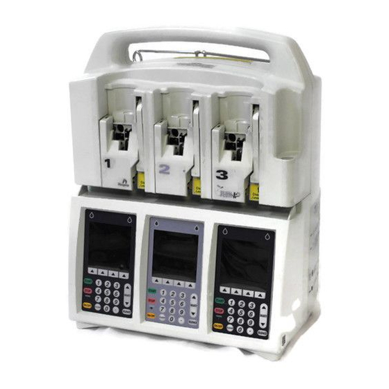
Hospira PLUMA+3 12348-04 Technical & Service Manual (247 pages)
INFUSION SYSTEM
Brand:
Hospira
| Category:
Medical Equipment
| Size: 15 MB
Table of Contents
Table of Contents
8
Table 1-1. Conventions
12
Figure 1-1. Display and Keypad
17
Table 1-2. System Configuration Data
19
Figure 1-3. IV Parameters
20
Figure 1-4. Alarms Log
21
Figure 1-5. Setting the Time and Date
22
Figure 1-6. Common IV Parameters
23
Figure 1-7. Macro IV Parameters
23
Figure 4-1. Electronic Functional Diagram
30
Figure 4-2. Serial Interface to ADC
35
Table 4-1. Analog Inputs
35
Table 4-2. Keypad Map
36
Table 4-3. CPU-Power Supply Interface
38
Table 4-4. CPU-Mechanism Interface Signals
39
Figure 4-3. System Startup and Shutdown Timing, Battery Powered
43
Figure 4-4. Stepper Motor Coils
46
Figure 4-5. Air Sensor Block Diagram
48
Figure 4-6. Pressure Sensor Excitation and Amplifier Block Diagram
50
Table 4-5. Power Supply PWA Interface Connections
52
Table 4-6. Peripheral PWA Interface Connections
53
Table 4-7. Peripheral Interface PWA Interface Connections
53
Table 4-8. CPU PWA Interface Connections
54
Table 4-9. Driver PWA Interface Connections
55
Table 4-10. APP PWA Interface Connections
55
Figure 4-7. Major Elements of the Dual-Channel Cassette
58
Figure 4-8. Fluid Path in the Cassette
59
Figure 4-9. Mechanism Valve Pins and Sensor Locations
61
Table 5-1. Cleaning Solutions
64
Figure 5-1. Display and Keypad
67
Figure 5-2. Rear View
70
Figure 5-3. Special Cassettes with Bubble Sensor Tips Removed
72
Figure 5-4. Distal Occlusion Test Setup
74
Table 6-1. Warning Messages
80
Table 6-2. Operational Alarm Messages and Corrective Actions
81
Table 6-3. Error Codes Requiring Technical Service
85
Table 6-4. Troubleshooting with the PVT
91
Figure 7-1. Bottom View
96
Figure 7-2. AC Power Cord, Retainer, Velcro Strap, and Battery Assembly
98
Figure 7-3. Separating the Front Enclosure, Rear Enclosure, and Main Chassis Assembly
101
Figure 7-4. Screw Placement Sequence
102
Figure 7-5. Peripheral Interface Assembly and Peripheral Pwas
104
Figure 7-6. Peripheral Interface Assembly Components
107
Figure 7-7. Lower Front Enclosure Gaskets
109
Figure 7-8. External Rear Enclosure Assembly Components
111
Figure 7-9. Internal Rear Enclosure Assembly Components
112
Table 9-1. Drawings
137
Index
138
Table 9-2. IPB for the Infuser
138
Advertisement
Advertisement
Related Products
Hospira Plum 360
Hospira PLUM XL Series
Hospira Plum XLM
Hospira Plum XLM with DataPort
Hospira Plum XLM with DataPort Veterinary
Hospira Plum XL
Hospira Lifecare PCA3
Hospira Plum A+
Hospira Plum 360 with Hospira MedNet System
Hospira 12618-04
Hospira Categories
Medical Equipment
Water Pump
Laboratory Equipment
More Hospira Manuals
Login
Sign In
OR
Sign in with Facebook
Sign in with Google
Upload manual
Upload from disk
Upload from URL