
Related Manuals for Hospira GemStar


Summary of Contents for Hospira GemStar
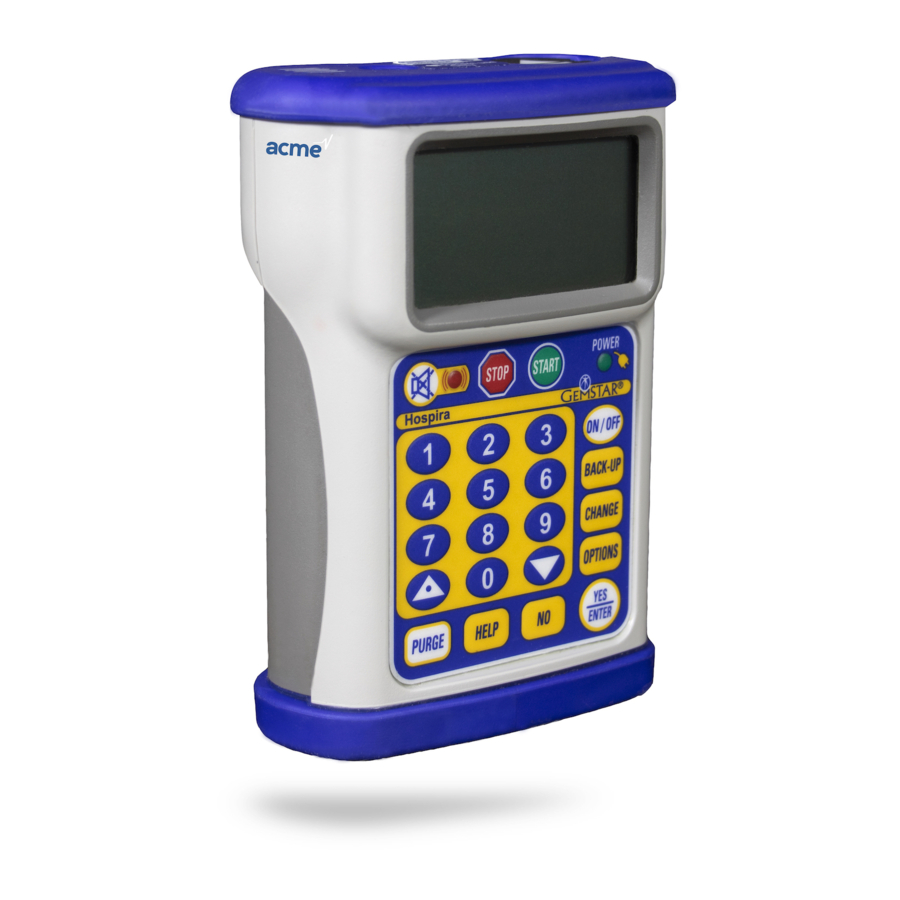
- Page 1 ® Advanced Ambulatory Infusion System For use with the following list numbers: 13086-04 13087-04 13088-04 Technical Service Manual 430-10786-002 (Rev. 01/07)
- Page 2 Hospira retains all the exclusive rights of dissemination, reproduction, manufacture, and sale. Any party using this document accepts it in confidence, and agrees not to duplicate it in whole or in part nor disclose it to others without the written consent of Hospira. ®...
- Page 3 Change History Part Number Description of Change 430-10786-001 Original issue (Rev. 05/06) 430-10786-002 Second issue (Rev. 01/07) Technical Service Manual 430-10786-002...
- Page 4 CHANGE HISTORY This page intentionally left blank. ® 430-10786-001 (Rev. 05/06) Hospira GemStar...
-
Page 5: Table Of Contents
Contents Section 1 INTRODUCTION ....... . . 1.1 SCOPE ........1.2 CONVENTIONS . - Page 6 5.2.12 RESTORING FOR USE ......5-24 5.3 PERIODIC MAINTENANCE INSPECTION....5-24 ® 430-10786-002 Hospira GemStar...
- Page 7 FIGURES Section 6 TROUBLESHOOTING ....... 6.1 TECHNICAL ASSISTANCE ......6.2 TROUBLESHOOTING REFERENCES.
- Page 8 Figure 5-16. Sample Test Result Printout ..... . . 5-23 Figure 9-1. Hospira GemStar PWA ......Tables Table 1-1.
-
Page 9: Introduction
If a problem in device operation cannot be resolved using the information in this manual, contact Hospira (see Section 6.1). ® Specific instructions for operating the device are contained in the Hospira GemStar System Operating Manual. Provision is made for the inclusion of the system operating manual in Section 3 of this manual. -
Page 10: Conventions
CAUTION: A CAUTION usually appears in front of a procedure or statement. It contains information that could prevent hardware failure, irreversible damage to equipment, or loss of data. Note: A note highlights information that helps explain a concept or procedure. ® 430-10786-002 1 - 2 Hospira GemStar... -
Page 11: Acronyms And Abbreviations
1.3 ACRONYMS AND ABBREVIATIONS ACRONYMS AND ABBREVIATIONS Acronyms and abbreviations used in this manual are as follows. A Ampere AC Alternating current A/D Analog-to-digital ADC Analog-to-digital converter CPU Central processing unit CRC Cyclic redundancy check DC Direct current DMM Digital multimeter ECG Electrocardiogram EEG Electroencephalogram EEPROM Electrically erasable programmable read-only memory... -
Page 12: User Qualification
Proper setup and maintenance of the monitoring equipment should eliminate the artifact. Refer to the appropriate monitoring system documentation for setup and maintenance instructions. ® 430-10786-002 1 - 4 Hospira GemStar... -
Page 13: Electromagnetic Compatibility
1.6 ELECTROMAGNETIC COMPATIBILITY ELECTROMAGNETIC COMPATIBILITY The Hospira GemStar is compliant with IEC/EN 60601-1-2 (2001), and has been tested and found to comply with electromagnetic compatibility (EMC) limits for the Medical Device Directive 93/42/EEC (EN 55011 Class B and EN 60601-1-2:2001). These limits are designed to provide reasonable protection against harmful interference in a typical medical installation (see the system operating manual). -
Page 14: Self Test
Note: If the infuser has been powered off for less than five minutes, a program review is not required. OVERVIEW The following sections describe therapy options, differences between therapies, safety features, power sources, and basic operation of the infuser. Figure 1-1 for an illustration of the infuser. ® 430-10786-002 1 - 6 Hospira GemStar... -
Page 15: Therapies
1.8 OVERVIEW 1.8.1 THERAPIES The Hospira GemStar offers the following types of therapy: - Pain Management - Continuous - Total Parenteral Nutrition (TPN) - mL/hr Only - Intermittent - Variable Time - Weight Dosed The availability of these programs may vary, depending upon the configuration of the infuser in use. -
Page 16: Safety Features
CAUTION: Always connect to a grounded AC outlet when using the AC adaptor. Use only an AC adaptor specifically labeled for use with the Hospira GemStar to charge the battery pack. During charging, if the battery pack becomes hot to the touch, immediately disconnect from AC power and contact Hospira Technical Support Operations. -
Page 17: Operation
The event history can be printed to a compatible printer or downloaded as an ASCII text file to a computer with the use of the Hospira GemStar serial printer cable. For specific instructions regarding infuser operation and optional system components, refer to the system operating manual. -
Page 18: Figure 1-1. Illustration Of The Infuser
AC POWER CONNECTOR BATTERY DOOR RECESS DATAPORT CONNECTOR BOLUS CONNECTOR CONNECTOR LABEL 3 V DC BO LU S BOTTOM CAP BATTERY DOOR BATTERY PACK CONNECTOR BOTTOM VIEW 04K02001 Figure 1-1. Illustration of the Infuser ® 430-10786-002 1 - 10 Hospira GemStar... -
Page 19: Warranty
(whether such cause be based in contract, negligence, strict liability, other tort, or otherwise) exceed the price of such product, and in no event shall Hospira be liable for incidental, consequential, or special damages or losses or for lost business, revenues, or profits. - Page 20 SECTION 2 WARRANTY This page intentionally left blank. ® 430-10786-002 2 - 2 Hospira GemStar...
-
Page 21: System Operating Manual
Section 3 SYSTEM OPERATING MANUAL A copy of the system operating manual is included with every Hospira GemStar. Insert a copy here for convenient reference. If a copy of the system operating manual is not available, contact Hospira Technical Support Operations (see Section 6.1). - Page 22 SECTION 3 SYSTEM OPERATING MANUAL This page intentionally left blank. ® 430-10786-002 3 - 2 Hospira GemStar...
-
Page 23: Theory Of Operation
Section 4 THEORY OF OPERATION This section describes the theory of operation for the Hospira GemStar. The theory of operation details the electro-mechanical and cassette systems. Related drawings are provided in Section ELECTRO-MECHANICAL SYSTEMS The following sections describe the functions and electronic circuitry of the infuser. -
Page 24: Figure 4-1. Hospira Gemstar Block Diagram
SECTION 4 THEORY OF OPERATION Figure 4-1. Hospira GemStar Block Diagram ® 430-10786-002 4 - 2 Hospira GemStar... -
Page 25: Figure 4-2. Board Connector References
4.1 ELECTRO-MECHANICAL SYSTEMS TOP BOARD KEYPAD CPU, MEMORY, RTC, SERIAL PORT DISPLAY J102 PUMP BOTTOM J109 EXTERNAL CONNECTOR J104 BATTERY SPRING MIDDLE BOARD J108 MOTOR CONTROL, BATTERY CONTACT POWER CONVERSION J107 MOTOR J106 J105 J205 J206 AUDIBLE BEEPER RECEIVER J207 TRANSMITTER BOTTOM BOARD PRESSURE SENSOR, AIR SENSOR... -
Page 26: Memory
When this happens, U1 interrupts program execution with a non-maskable interrupt via signal /PFO. This interrupt signals the microprocessor to execute a power-down routine that gracefully stops the motor, saves current data, and powers off the infuser. ® 430-10786-002 4 - 4 Hospira GemStar... -
Page 27: Power-On Reset
4.1 ELECTRO-MECHANICAL SYSTEMS 4.1.2.2 POWER-ON RESET During power-on or other reset conditions, the supervisory circuit holds the system in reset for 200 ms after V reaches 3 V to assure the system has stable power prior to starting normal operation. During reset conditions, the reset signal interfaces with all circuitry to assure conditions are held in a safe operational state (e.g., motor stopped). -
Page 28: Wdt Pic/Beeper Pic/Beeper Driver
FPGA outputs. The green LED illuminates when AC mains power is connected to the infuser. The red LED illuminates during an alarm condition, and is accompanied by an audible alarm and a display message, when applicable. ® 430-10786-002 4 - 6 Hospira GemStar... -
Page 29: Bolus Switches
4.1 ELECTRO-MECHANICAL SYSTEMS 4.1.5 BOLUS SWITCHES Patients can request a bolus dose for pain management and variable time protocols. The bolus switch is located on the top of the infuser and is protected by a rubber end cap. The bolus switch signal (logic low) is buffered, inverted, and passed to the FPGA as the bolus request (BOLUSREQ) signal. -
Page 30: Figure 4-3. Power Input
U110 100K VREF (1.2V) INPUT SOURCE POWER SWITCHING D108B R156 VPWR EXT PWR IN 499K D107B R155 4.99K D108A R157 3.3V 4.99K 02K02009 SOURCES FOR SUPPLYING Vcc TO U110 Figure 4-3. Power Input ® 430-10786-002 4 - 8 Hospira GemStar... -
Page 31: Internal Power Supplies
4.1 ELECTRO-MECHANICAL SYSTEMS 4.1.8 INTERNAL POWER SUPPLIES The input power at V is converted to three operating voltages: +3.3 V, +5 V, and –5 V. The 3.3 V supply is U109, an LTC3401 outputting 3.3 V on pin 7. This switch-mode regulator has internal FETs that ground inductor L103 and direct flyback current to the output capacitor. -
Page 32: Power Off
(encoder counts). The CPU also monitors the activation of the cassette (via output shaft encoder) to verify that motor turns are correctly converted into fluid delivery actions (see Figure 4-4 Figure 4-5). ® 430-10786-002 4 - 10 Hospira GemStar... -
Page 33: Figure 4-4. Motor Control Circuit
4.1 ELECTRO-MECHANICAL SYSTEMS R105 301K R106 100K MOTCNTRL AMPLIFIER MOT+ 1.24V REFERENCE U102, Q101, Q102 Q103, Q108, D101 02K02013 Figure 4-4. Motor Control Circuit MOT SPCTL MOT+ R105 R112 150K R110 200K MOTOR R106 U103B TO U102-3 R111 R114 R120 MOT DREN U103A R121... -
Page 34: Speed Control
5 V line (MOTOR5V). When positive 5 V is available on MOTOR5V, U101, a MAX828 voltage inverter, generates a -5 V (MD-5V) for the negative rail of the op-amps and for FET switching. ® 430-10786-002 4 - 12 Hospira GemStar... -
Page 35: Motor
4.1 ELECTRO-MECHANICAL SYSTEMS 4.1.10.3 MOTOR The drive motor is a combined gear motor with integral quadrature tachometer. The gearbox following the motor divides the motor speed by 27. The motor speed constant is chosen such that with the maximum voltage available from the servo, the motor output shaft will turn at a speed sufficient to provide approximately 1000 mL/hr. -
Page 36: Motor Tachometer Power Conservation
To minimize power consumption, the shaft encoder is enabled for only 140 µs for a 2 % duty cycle. The shaft-on (SHFT-ON) control signal is generated at the FPGA, passes through connectors J3, J103, J105, and J205 to R224 and U208. ® 430-10786-002 4 - 14 Hospira GemStar... -
Page 37: Air-In-Line Sensing
4.1.13 AIR-IN-LINE SENSING The Hospira GemStar uses an ultrasonic air detection system. The mechanism holds a sound generator on one side of the IV tubing and a receiver on the opposite side. If there is fluid inside the tubing, the sound is conducted to the receiver and a strong signal results. -
Page 38: Distal Pressure Measurement
When latched closed, it causes the outlet valve to remain in the closed position, preventing fluid flow when the cassette is outside of the infuser. The cassette consists of four parts: body, top, diaphragm, and flow stop. ® 430-10786-002 4 - 16 Hospira GemStar... -
Page 39: Body And Top
4.2 CASSETTE SYSTEM 4.2.1 BODY AND TOP The body and top enclose the silicone diaphragm to form the inlet, pumping, and outlet chambers. The flexible diaphragm mates to the body to enclose the chambers and form the one-way valves. The pump plunger presses on the diaphragm to empty the pumping chamber and when the plunger retracts, the spring force of the diaphragm refills the pumping chamber. - Page 40 SECTION 4 THEORY OF OPERATION This page intentionally left blank. ® 430-10786-002 4 - 18 Hospira GemStar...
-
Page 41: Maintenance And Service Tests
Section 5 MAINTENANCE AND SERVICE TESTS A complete maintenance program promotes infuser longevity and trouble-free operation. Such a program should include routine maintenance, operation testing, and periodic maintenance inspection. This section details routine maintenance procedures and the operation test. Note: Store the infuser in a cool, dry place. -
Page 42: Sanitizing
CAUTION: Certain cleaning and sanitizing compounds may slowly degrade components made from some plastic materials. Using abrasive cleaners or cleaning solutions not recommended by Hospira may result in product damage and, potentially, void the product warranty. Do not use compounds containing combinations of isopropyl alcohol and dimethyl benzyl ammonium chloride. -
Page 43: Cleaning The Cassette Pocket And Tubing Channel
5.1 ROUTINE MAINTENANCE 5.1.1.2 CLEANING THE CASSETTE POCKET AND TUBING CHANNEL Clean the cassette pocket and the tubing channel on a regular basis. The ultrasonic sensors are located in the cassette pocket. CAUTION: Do not damage the silicone seals around the sensor bodies. Figure 5-1 and proceed as follows: 1. -
Page 44: Inspection
Infuser inspection requires the following materials: - Cotton swab - Cleaning solution - Infuser administration set - Small flashlight - Two fresh AA disposable batteries - 3 V AC adaptor - Digital multimeter (DMM) (optional) ® 430-10786-002 5 - 4 Hospira GemStar... -
Page 45: Latch Mechanism Inspection
5.1 ROUTINE MAINTENANCE 5.1.2.2 LATCH MECHANISM INSPECTION Figure 5-2 and proceed as follows: 1. Verify the four cassette latches are present. 2. Load a cassette into the chassis pocket and push the cassette until all four cassette latches securely hold the cassette in place. 3. -
Page 46: Air Sensor Inspection
The seals should not interfere with contact between the anvil face and the set tubing. 5. Verify sensor seal pockets sensor anvils free debris and contamination. 02K02022 Figure 5-3. Air Sensor Inspection ® 430-10786-002 5 - 6 Hospira GemStar... -
Page 47: Plunger And Pressure Sensor Inspection
5.1 ROUTINE MAINTENANCE 5.1.2.4 PLUNGER AND PRESSURE SENSOR INSPECTION CAUTION: DO NOT apply excessive force to pressure sensor pins. Excessive force may damage sensor pins or internal beams. Figure 5-4 and proceed as follows: 1. Verify the plunger seal is present and in good condition. 2. -
Page 48: Top Cap Inspection
1. Verify the top cap is free of cracks, holes, and evidence of fluid ingress. 2. Verify the seal between the top cap and the bezel/extrusion is present and in good condition. 3. Verify the condition of the pole clamp retainer. 02K02024 Figure 5-5. Top Cap Inspection ® 430-10786-002 5 - 8 Hospira GemStar... -
Page 49: Bottom Cap Inspection
2. Verify the bottom cap is free of cracks and holes. 3. Verify all three hole plugs are present. Note: Step 4 through Step 6 apply to the Hospira GemStar with the optional system component interface. 4. Verify each port is free of foreign material and contamination. -
Page 50: Bezel, Grip, And Keypad Inspection
5. Verify the seal of the bezel face edge to extrusion. 6. Verify the keypad is free of damage and that each key provides tactile feedback when pressed. Figure 5-7. Bezel, Grip, and Keypad Inspection ® 430-10786-002 5 - 10 Hospira GemStar... -
Page 51: Battery Door And Compartment Inspection
5.1 ROUTINE MAINTENANCE 5.1.2.8 BATTERY DOOR AND COMPARTMENT INSPECTION The following sections describe battery door and battery compartment inspection. 5.1.2.8.1 Battery Door Engagement Figure 5-8 and proceed as follows: 1. Flip the door latch to the open position, then to the closed position, then to the open position again. -
Page 52: Figure 5-9. Battery Door Inspection
3. Verify the door latch and plunger hinges are free of fractures. 4. Verify the spring is secure with no wobble or excessive collapse. 5. Verify the wiper contact is free of contamination, corrosion, and excessive deformation. Figure 5-9. Battery Door Inspection ® 430-10786-002 5 - 12 Hospira GemStar... -
Page 53: Figure 5-10. Battery Compartment Inspection
5.1 ROUTINE MAINTENANCE 5.1.2.8.3 Battery Compartment Inspection Figure 5-10 and proceed as follows: 1. Remove the battery door. 2. Verify the circuit board wiper contact is present and free of contamination, corrosion, and excessive deformation. 3. Verify the battery cap is present and free of contamination and corrosion. Figure 5-10. -
Page 54: Power-On Test
3. Verify the audible alarm sounds at power-on. 4. Verify USING BATTERIES displays, then press [YES/ENTER] and confirm the appearance of the HOSPIRA screen and the Main Program menu. 5. Connect the AC adaptor to the 3 V connector on the bottom of the infuser, and verify the green power LED illuminates. -
Page 55: Rechargeable Battery Pack
5.1 ROUTINE MAINTENANCE 5.1.2.10 RECHARGEABLE BATTERY PACK Figure 5-12 and proceed as follows: 1. Verify the 3 V /printer/bolus port connector contacts are present and in good condition. 2. Verify the 3 V /printer/bolus pass-through port connector contacts are present and in good condition. -
Page 56: Docking Station
11. Press [ON/OFF]. Verify the infuser powers on and initiates the self test. 12. Remove the infuser, disconnect power, and perform a continuity test between the corresponding top and bottom pins to verify bolus pass-through functionality. ® 430-10786-002 5 - 16 Hospira GemStar... -
Page 57: Figure 5-13. Docking Station
5.1 ROUTINE MAINTENANCE Figure 5-13. Docking Station Technical Service Manual 5 - 17 430-10786-002... -
Page 58: Ac Adaptor
5. Connect the AC adaptor to the adaptor port on the bottom of the infuser. Verify the AC plug is properly engaged/retained. 6. Remove the batteries. 7. Press [ON/OFF], and verify the infuser powers on. Figure 5-14. AC Adaptor ® 430-10786-002 5 - 18 Hospira GemStar... -
Page 59: Remote Bolus Cord And Switch
5.1 ROUTINE MAINTENANCE 5.1.2.13 REMOTE BOLUS CORD AND SWITCH Figure 5-15 and proceed as follows: 1. Verify the bolus cord is free from fraying and torn insulation. 2. Verify the switch body is free of damage and evidence of fluid ingress. 3. -
Page 60: Operation Test
The operation test consists of the tests described in the following sections and is designed to assure the Hospira GemStar is operating properly. The infuser display provides step-by-step guidance through each section of the test. Follow the instructions on the display to complete the tests. -
Page 61: Power Test
5.2 OPERATION TEST 5.2.3 POWER TEST 1. Verify the display indicates that an external power source and batteries are connected (see Figure 5-11). 2. Remove the disposable AA batteries and press the [DOWN] arrow. Verify the display indicates that only external power is connected, and press the [DOWN] arrow. 3. -
Page 62: Volume Accuracy Test
- If the test has failed, clean the sensor faces and sensor pins then press the [UP] arrow to rerun the test, or press [YES/ENTER] to confirm failure. 3. Press the [DOWN] arrow and release the clamp. ® 430-10786-002 5 - 22 Hospira GemStar... -
Page 63: Air-In-Line Test
5.2 OPERATION TEST 5.2.10 AIR-IN-LINE TEST To pass the air-in-line test, the alarm must occur within approximately one minute. 1. Remove the proximal end of the set from the reservoir, and press the [DOWN] arrow. 2. Press [START]. 3. One of the following test results displays: - If the test has passed, the infuser advances to the next test. -
Page 64: Restoring For Use
It is recommended that JCAHO and/or hospital protocol be followed for establishing a periodic maintenance inspection schedule. Product specifications for this inspection are listed in Section To perform the periodic maintenance inspection, complete the operation test in Section 5.2. ® 430-10786-002 5 - 24 Hospira GemStar... -
Page 65: Troubleshooting
Morgan Hill, California 95037 For technical assistance, product return authorization, and to order parts, accessories, or manuals from outside the United States, contact the nearest Hospira sales office. TROUBLESHOOTING REFERENCES The following information is provided to assist in troubleshooting the Hospira GemStar. -
Page 66: Troubleshooting Tools
FLASHING DISPLAY PROGRAM INCOMPLETE START Sensor alarm AIR-IN-LINE DISTAL OCCLUSION PROXIMAL OCCLUSION Alarm message CHANGE BATTERIES CHECK CASSETTE LOW BATTERIES POWER LOSS USING BATTERIES Service alarm CALL 1-800-241-4002 Section 6.1 CODE: NN/MMM/TTT Section 6.3 ® 430-10786-002 6 - 2 Hospira GemStar... - Page 67 6.2 TROUBLESHOOTING REFERENCES Table 6-2. Alert/Alarm Message Index Error Type Display/Description Reference Other display messages KEYPAD LOCKED System Operating Manual NOT ALLOWED DURING INFUSION PROCESS PRESS STOP TO HALT DELIVERY ROUNDING DOSE IN PROGRESS NEW CONTAINER NOT ALLOWED CANNOT CHANGE CLOCK WHILE THE BASE DELIVERY IS IN PROGRESS...
-
Page 68: Printing Device History
EEPROM write error – data read back does not match data written 05/001 EEPROM write error – invalid EEPROM address 06/000 Pump configuration CRC error 06/001 Infusion data CRC error 06/002 Pump data CRC error ® 430-10786-002 6 - 4 Hospira GemStar... - Page 69 6.3 SERVICE ALARM CODES Table 6-3. Service Alarm Codes - Quick Reference Error Description 06/003 Program data CRC error 06/004 Speed protocol CRC error 06/005 ROM CRC error 06/006 Protected variable error 06/007 Dose data CRC error 06/008 Air calibration CRC error 06/009 Pressure calibration CRC error 06/010...
- Page 70 Infusion safety task did not receive the expected queue information 16/013 Infusion safety task received an invalid semaphore value 16/014 Infusion safety task received an invalid air message 16/015 Infusion safety task received an invalid check cassette message ® 430-10786-002 6 - 6 Hospira GemStar...
- Page 71 6.3 SERVICE ALARM CODES Table 6-3. Service Alarm Codes - Quick Reference Error Description 16/016 Infusion safety task received a resume without an initial start 16/017 Infusion safety task detects an rate mismatch 16/018 Infusion safety task detects a mode mismatch 16/019 IED has message conflict 16/020...
-
Page 72: Service Alarm Codes - Details
2 = PAIE_INTERRUPT a service alarm Flash RAM 11 = TIC2_INTERRUPT failure 12 = TIC1_INTERRUPT Bus failure 18 = NOCOP_ CPU failure INTERRUPT RAM chip 19 = CME_INTERRUPT failure ® 430-10786-002 6 - 8 Hospira GemStar... - Page 73 6.3 SERVICE ALARM CODES Table 6-4. Service Alarm Codes - Details Error Primary Supplemental Error Description Error Error Type Detection (NN) (MMM) (TTT) Method Possible Cause Interrupt # Each interrupt An interrupt was INTERRUPT_ INTERRUPT_ service routine has called again before 0 = SCI_INTERRUPT ERROR OVERLAP...
- Page 74 If the CRC stored with the configuration data does not match the calculated value, a service alarm occurs. ® 430-10786-002 6 - 10 Hospira GemStar...
- Page 75 6.3 SERVICE ALARM CODES Table 6-4. Service Alarm Codes - Details Error Primary Supplemental Error Description Error Error Type Detection (NN) (MMM) (TTT) Method Possible Cause The infusion data The computed CRC_ INFUSION_ integrity is verified infusion data CRC CHKSUM_ DATA_CRC at power on and does not match the...
- Page 76 When read back, CPU failure 007 = Proximal pressure the data and its threshold mirrored value is compared to verify data integrity. If the data value cannot be verified, a service alarm occurs. ® 430-10786-002 6 - 12 Hospira GemStar...
- Page 77 6.3 SERVICE ALARM CODES Table 6-4. Service Alarm Codes - Details Error Primary Supplemental Error Description Error Error Type Detection (NN) (MMM) (TTT) Method Possible Cause Dose type The dose data The computed CRC_ DOSE_DATA_ integrity is verified dose data CRC CHKSUM_ at power on, once does not match the...
- Page 78 CALIBRATED to see that it is not are not within the zero at power on expected ranges due to: If it is zero, a service alarm calibration error occurs. EEPROM failure ® 430-10786-002 6 - 14 Hospira GemStar...
- Page 79 6.3 SERVICE ALARM CODES Table 6-4. Service Alarm Codes - Details Error Primary Supplemental Error Description Error Error Type Detection (NN) (MMM) (TTT) Method Possible Cause The volume Excessive volume AIR_ AIR_ delivered between sampled due to: SENSOR_ EXCESSIVE_ checkpoints is RAM chip failure ERROR VOLUME...
- Page 80 There are several exceptions: Step 0 of any delivery Step 7 of an 8-step delivery Steps 13, 14, and 15 of a 16-step delivery ® 430-10786-002 6 - 16 Hospira GemStar...
- Page 81 6.3 SERVICE ALARM CODES Table 6-4. Service Alarm Codes - Details Error Primary Supplemental Error Description Error Error Type Detection (NN) (MMM) (TTT) Method Possible Cause Step where problem The last step of Microprocessor MOTOR_ MOTOR_IPRF_ occurred a stroke frequently misses motor ERROR ENC_OS_SYNC...
- Page 82 29/ccc/nnn Where: ppp = distal pressure (ADC) rrr = rollback amount, ticks ccc = count of large rollbacks within this 16-stroke window nnn = net position (forward–back counts) at start of this step ® 430-10786-002 6 - 18 Hospira GemStar...
- Page 83 6.3 SERVICE ALARM CODES Table 6-4. Service Alarm Codes - Details Error Primary Supplemental Error Description Error Error Type Detection (NN) (MMM) (TTT) Method Possible Cause Error type The motor The motor MOTOR_ MOTOR_NOT_ calibration values calibration values 0 = Invalid PWM ERROR CALIBRATED are tested at...
- Page 84 = distal occlusion alarm condition (1 = on) ccc = check cassette alarm condition (1 = on) aal = air alarm condition (1 = on) prx = proximal occlusion alarm condition (1 = on) ® 430-10786-002 6 - 20 Hospira GemStar...
- Page 85 6.3 SERVICE ALARM CODES Table 6-4. Service Alarm Codes - Details Error Primary Supplemental Error Description Error Error Type Detection (NN) (MMM) (TTT) Method Possible Cause State # If the motor state The motor state MOTOR_ MOTOR_BAD_ variable is out of variable was invalid ERROR STATE...
- Page 86 = NetGood = (ggg * 100) + hhh NetGood reports the net counts (FINE_POS) of the last step that was within tolerance (two steps before the one reported in the 09/015 alarm) ® 430-10786-002 6 - 22 Hospira GemStar...
- Page 87 6.3 SERVICE ALARM CODES Table 6-4. Service Alarm Codes - Details Error Primary Supplemental Error Description Error Error Type Detection (NN) (MMM) (TTT) Method Possible Cause Type 1: Pulse accumulator For purposes The motor encoder MOTOR_ MOTOR_ of this alarm, overflow count was back counts in previous ERROR...
- Page 88 (i.e., high byte at end of dose to low byte, and ^ motor start is exponentiation) without fff/ggg/hhh/iii = total permission observed output shaft turns, expressed high byte to low byte as above ® 430-10786-002 6 - 24 Hospira GemStar...
- Page 89 6.3 SERVICE ALARM CODES Table 6-4. Service Alarm Codes - Details Error Primary Supplemental Error Description Error Error Type Detection (NN) (MMM) (TTT) Method Possible Cause Error Every five seconds, The infuser is MOTOR_ MOTOR_ the infusion safety delivering at too 1 = Too fast ERROR UNDER_...
- Page 90 5 V line due to: second. 5 V regulator If the voltage is less failure than expected power sensing a service alarm circuitry failure occurs. ® 430-10786-002 6 - 26 Hospira GemStar...
- Page 91 6.3 SERVICE ALARM CODES Table 6-4. Service Alarm Codes - Details Error Primary Supplemental Error Description Error Error Type Detection (NN) (MMM) (TTT) Method Possible Cause ADC battery compartment The AA battery More than 3.2 volts POWER_ OVERVOLT_ input reading input line is tested measured on the SENSING_...
- Page 92 IRQ interrupt each RTI. failure If the number exceeds the upper limit value since the last one second interrupt, a service alarm occurs. ® 430-10786-002 6 - 28 Hospira GemStar...
- Page 93 6.3 SERVICE ALARM CODES Table 6-4. Service Alarm Codes - Details Error Primary Supplemental Error Description Error Error Type Detection (NN) (MMM) (TTT) Method Possible Cause Reading of PACNT At power on, Watchdog PIC WATCHDOG_ the watchdog circuit is not ERROR PIC is tested by functioning,...
- Page 94 ALARM_ values when alarm semaphore SEMAPHORE received. value due to: If processing RAM chip failure is not defined for Bus failure a semaphore value, a service alarm occurs. ® 430-10786-002 6 - 30 Hospira GemStar...
- Page 95 6.3 SERVICE ALARM CODES Table 6-4. Service Alarm Codes - Details Error Primary Supplemental Error Description Error Error Type Detection (NN) (MMM) (TTT) Method Possible Cause Action value The alarm task The alarm task SOFTWARE_ INVALID_ verifies actions received an invalid ERROR ALARM_ requested when...
- Page 96 If processing RAM chip failure is not defined Bus failure for an air message value, a service alarm occurs. ® 430-10786-002 6 - 32 Hospira GemStar...
- Page 97 6.3 SERVICE ALARM CODES Table 6-4. Service Alarm Codes - Details Error Primary Supplemental Error Description Error Error Type Detection (NN) (MMM) (TTT) Method Possible Cause Bad check cassette code The infusion safety The infusion safety SOFTWARE_ ISA_BAD_CK_ task verifies check task received an ERROR CASS_CODE...
- Page 98 If a tapered rate software error ISA_BAD_ is greater than 2 = Standard delivery RAM error RATE 450 mL/hr or overrate error a non-tapered rate is greater than 1000 mL/hr, a service alarm occurs. ® 430-10786-002 6 - 34 Hospira GemStar...
- Page 99 6.3 SERVICE ALARM CODES Table 6-4. Service Alarm Codes - Details Error Primary Supplemental Error Description Error Error Type Detection (NN) (MMM) (TTT) Method Possible Cause xxx: debug information Each time a record History pointers HISTORY_ WRITE_HLOG_ is written to the became corrupted PTR_ERROR ERROR...
- Page 100 IN_MSG_ERR BAD_MSG_TYPE task receives an communication unknown message error type, a service alarm occurs. When SCI input Data IN_MSG_ERR BAD_SESS_RQST task receives a bad communication session request error message, a service alarm occurs. ® 430-10786-002 6 - 36 Hospira GemStar...
-
Page 101: Operational Alarms
Y-site and there is a backcheck valve in place. Fluid must be injected slowly (i.e., at the delivery rate or less). User pressed syringe during delivery. Use Hospira recommended syringe sizes, and use a syringe adapter for very small-bore syringes. - Page 102 ADC value measured by the infuser. Power Loss H or S H if the power loss was initiated by the hardware S if the power loss was initiated by the software ® 430-10786-002 6 - 38 Hospira GemStar...
-
Page 103: Replaceable Parts And Repairs
Section 7 REPLACEABLE PARTS AND REPAIRS The Hospira GemStar has no user-serviceable components, with the following exceptions: - disposable batteries - battery door To replace the disposable batteries, see Figure 5-11. To replace the battery door, see Section 5.1.2.8, Figure... - Page 104 SECTION 7 REPLACEABLE PARTS AND REPAIRS This page intentionally left blank. ® 430-10786-002 7 - 2 Hospira GemStar...
-
Page 105: Specifications
Section 8 SPECIFICATIONS The following specifications apply to the Hospira GemStar infuser. PHYSICAL Dimensions: Height: 5.5 in. (14.0 cm) Width: 3.8 in. (9.7 cm) Depth: 2 in. (5.1 cm) Weight: Approximately 17 oz. (482 grams) excluding batteries TRANSPORT AND STORAGE ENVIRONMENT Store in cool and dry environment Ambient Temperatures: -4°... - Page 106 Port and Interface: RS-232 serial interface port; minimum baud rate of 2400; isolated circuit Printers: Seiko DPU 414 or compatible serial printer SYSTEM ACCURACY ± 10% for rates of 0.1 to less than 5 mL/hr ± 5% for rates of 5 to 1000 mL/hr ® 430-10786-002 8 - 2 Hospira GemStar...
- Page 107 AIR SENSITIVITY ON: Infuser alarms at approximately 0.5 mL of air Alarms for any bubble greater than 500 microliters with a tolerance of 200 microliters 2 mL: Infuser alarms at approximately 2 mL of air Alarms when infuser detects 2 +1/-0.2 mL of air in 6 mL of total volume delivered OFF: Alarm is not activated OCCLUSION...
- Page 108 SECTION 8 SPECIFICATIONS This page intentionally left blank. ® 430-10786-002 8 - 4 Hospira GemStar...
-
Page 109: Drawings
Section 9 DRAWINGS Drawings in Section 9 are provided as information only, and may not exactly reflect current product configuration. Figure 9-1 shows the Hospira GemStar PWA configuration. Technical Service Manual 9 - 1 430-10786-002... - Page 110 SECTION 9 DRAWINGS This page intentionally left blank. ® 430-10786-002 9 - 2 Hospira GemStar...
- Page 111 HOSPIRA Figure 9-2. Hospira GemStar PWA Rev. N/A DRAWING NO. Sheet 1 of 1 Technical Service Manual 9 - 3 430-10786-002...
- Page 112 SECTION 9 DRAWINGS This page intentionally left blank. ® 430-10786-002 9 - 4 Hospira GemStar...
- Page 113 APPENDIX USE OF THE INFUSION SYSTEM IN ELECTROMAGNETIC ENVIRONMENTS EN-2 The Hospira GemStar (outside the United States) is intended for use in the electromagnetic environment specified in Electromagnetic Emissions, Electromagnetic Immunity, and Electromagnetic Immunity for Life-Supporting Equipment and Systems. The user should assure that it is used only in the appropriate environment.
-
Page 114: Table A-2. Guidance And Manufacturer's Declaration - Electromagnetic Immunity
APPENDIX ELECTROMAGNETIC IMMUNITY Table A-2 details guidance for the electromagnetic environment for the Hospira GemStar. Table A-2. Guidance and Manufacturer’s Declaration - Electromagnetic Immunity Electromagnetic Immunity Test IEC 60601 Test Level Compliance Level Environment Guidance Electrostatic ±6 kV Contact ±8 kV Contact... -
Page 115: Table A-3. Guidance And Manufacturer's Declaration - Electromagnetic Immunity
APPENDIX ELECTROMAGNETIC IMMUNITY FOR LIFE-SUPPORTING EQUIPMENT AND SYSTEMS Table A-3 provides guidance for use of the Hospira GemStar near communications equipment. Table A-3. Guidance and Manufacturer’s Declaration - Electromagnetic Immunity for Life-Supporting Equipment and Systems Immunity IEC 60601 Compliance Electromagnetic Immunity... - Page 116 If abnormal performance is observed, additional measures may be necessary, such as re-orienting or relocating the infuser. Over the frequency range 150 kHz to 80 MHz, field strengths should be less than [V ] V/m. ® 430-10786-001 (Rev. 05/06) A - 4 Hospira GemStar...
-
Page 117: Table A-4. Recommended Separation Distances Between Portable And Mobile Rf
APPENDIX RECOMMENDED SEPARATION DISTANCES FOR COMMUNICATIONS EQUIPMENT The Hospira GemStar is intended for use in an electromagnetic environment in which radiated RF disturbances are controlled. The recommendations provided in Table A-4 help the user prevent electromagnetic interference by maintaining a minimum distance between portable and mobile RF communications equipment (transmitters) and the infuser, according to the maximum output power of the communications equipment. - Page 118 APPENDIX This page intentionally left blank. ® 430-10786-001 (Rev. 05/06) A - 6 Hospira GemStar...
-
Page 119: Index
5-21 Alert/alarm message index, Distal occlusion test, 5-22 Artifacts, Distal pressure measurement, 4-16 Docking station, 5-16 Drawings, Hospira GemStar PWA, Battery door and compartment inspection, 5-11 Battery compartment inspection, 5-13 Battery door engagement, 5-11 Electromagnetic compatibility, Battery door inspection, 5-12... - Page 120 Proximal pressure measurement, 4-15 Memory and time retention, Motor, 4-13 Motor drive circuits, 4-10 Motor, 4-13 Power conservation, 4-12 Redundant motor control, 4-13 Speed control, 4-12 Tachometer, 4-13 Motor tachometer power conservation, 4-14 ® 430-10786-002 I - 2 Hospira GemStar...
- Page 121 Rechargeable battery pack, 5-15 Unpacking, Redundant motor control, 4-13 User qualification, Remote bolus cord and switch, 5-19 Replaceable parts and repairs, Restoring for use, 5-24 Routine maintenance, Volume accuracy test, 5-22 Cleaning, Inspection, Sanitizing, RS-232 interface system, 4-16 Warranty, Watchdog function, WDT PIC/beeper PIC/beeper driver, Safety features, Sanitizing,...
- Page 122 INDEX This page intentionally left blank. ® 430-10786-002 I - 4 Hospira GemStar...
- Page 123 Technical Support Operations 755 Jarvis Drive Morgan Hill, California 95037 For technical assistance and services outside the United States, contact the local Hospira sales office. CAUTION: Federal (USA) law restricts this infuser to sale by or on the order of a physician or other licensed practitioner.
Need help?
Do you have a question about the GemStar and is the answer not in the manual?
Questions and answers