Table of Contents
Advertisement
Quick Links
Advertisement
Table of Contents

Subscribe to Our Youtube Channel
Related Manuals for IAI IF


Summary of Contents for IAI IF
- Page 1 IF Actuator Operating Manual Eighth Edition IAI America, Inc.
- Page 3 It should be noted that the instructions under the Caution and Note headings may also lead to serious consequences, if unheeded, depending on the situation. All instructions contained herein provide vital information for ensuring safety. Please read the contents carefully and handle the product with due caution.
- Page 4 In particular, observe the maximum loading capacity and speed. [Installation] ● If the machine will stop in the case of system problem such as emergency stop or power failure, design a safety circuit or other device that will prevent equipment damage or injury.
- Page 5 ● Do not use the product in an area where it may come in contact with corrosive gases (sulfuric acid, hydrochloric acid, etc.). The product may lose its strength due to rust. ● Provide sufficient shielding measures if the product is used in any of the following places. If proper measures are not taken, the product may malfunction: 1.
- Page 6 Note [Installation] ● If the product is used in a vertical setup, be sure to use the vertical specification (with brake). ● Protection covers or other guards must be provided for the moving parts of the equipment to avoid direct contact with the operators.
- Page 7 NTELLIGENT ACTUATOR Prohibited Handling of Cables When designing an application system using IAI’s actuators and controllers, incorrect wiring or connection of each cable may cause unexpected problems such as a disconnected cable or poor contact, or even a runaway system. This section explains prohibited handling of cables. Read the information carefully to connect the cables properly.
- Page 8 NTELLIGENT ACTUATOR Notes on using cable bearers ● The supplied cables are not robot cables. Accordingly, never store the cables in a cable bearer. ● Always use a robot cable for each relay cable. Bending radius (r) ● Use a cable bearer with a bending radius (r) of 50 mm or greater.
-
Page 9: Table Of Contents
NTELLIGENT ACTUATOR Table of Contents 1. Foreword ........................1 2. Safety Precautions ....................1 ..................1 2.1 Basic Operating Instructions ..................1 2.2 Maintenance and Inspection 3. Warranty ........................2 ...................... 2 3.1 Warranty Period ....................2 3.2 Scope of Warranty 4. - Page 10 NTELLIGENT ACTUATOR 8. Connecting the Controller ..................11 9. Load On the Actuator ....................12 10. Setting the Home Position ..................14 ................14 10.1 Principle of the Homing Operation ................14 10.2 Fine Control of the Home Position ................. 14 10.3 Changing the Home Direction ..................
-
Page 11: Foreword
• Make sure that a sign indicating work in progress is clearly visible. • If several persons are working, be sure to watch out for each other's safety. In particular, check before turning power ON or OFF and let others know if you are doing work involving axis movement. -
Page 12: Warranty
• 2500 hours of operation time 3.2 Scope of Warranty If a breakdown occurs within the period specified above and is due to the manufacturer's error, we will repair the unit at no cost. However, the following items are not covered by this warranty. -
Page 13: Names Of The Parts
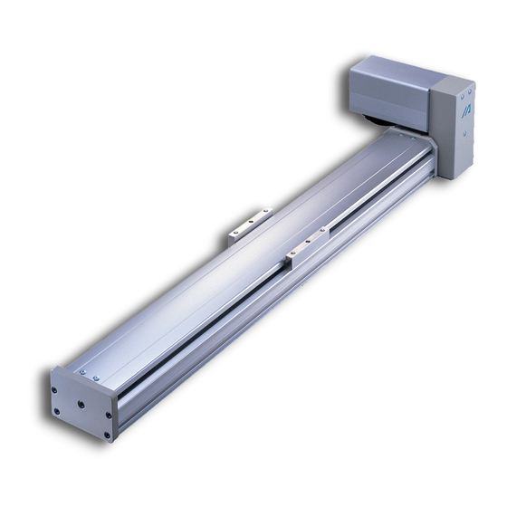
NTELLIGENT ACTUATOR 4. Names of the Parts In this manual, the left and right sides are indicated by viewing the actuator from the upper and the motor sides with the actuator set down horizontally. The front side shown in this manual is the opposite from the motor side. Motor cover Right Side Belt cover... -
Page 14: Transporting • Handling
• The operator should not carry heavy shipping boxes by himself. • If the shipping box is left standing, it should be in a horizontal position. • Do not climb on top of the shipping box. -
Page 15: Handling Of The Assembled Unit
NTELLIGENT ACTUATOR 5.2 Handling of the Assembled Unit When the actuator is carried with all the axes installed, follow the instructions below. 5.2.1 Shipping of the Assembled Unit from Our Company For the specified machine, after it is assembled in our company, the delivery inspection is performed and the machine is packed with the outer frame nailed onto the skid. -
Page 16: Installation And Storage Enviroment
The unit can withstand up to 60ºC during a short storage interval but only up to 50ºC if the storage period is longer than one month. -
Page 17: Installation
φB Machine Type Mounting Bolt Small 50mm Medium 70mm Caution Make sure to use the attached special washer. If the actuator is mounted without using this washer, the bolt might be loosened due to the buckling on the bolt-seated surface. -
Page 18: Mounting Surface
NTELLIGENT ACTUATOR 7.2 Mounting Surface • The mounting table should have sufficient rigidity to avoid generating vibration. • The surface where the actuator will be mounted should be machined or be equally level and the flatness tolerance between the actuator and the table should be within 0.05mm. •... -
Page 19: Clamp Screws
• When attaching the base to a mounting table, use the special washer made for high strength bolts that comes with the actuator if the bolt is M8 or larger. This is unnecessary for M6 or smaller bolts. Do not use a common spring washer. -
Page 20: Attaching The Slider Carrying The Payload
• To do this, follow the mounting procedure used for the main body. • If you are anchoring the slider and moving the main body, attach the slider using the tapped holes. • The slider has two reamed holes which are used to reproduce the correct positioning when dismounting and reattaching the slider. -
Page 21: Connecting The Controller
• In an application where the cable cannot be anchored, try to place the cable where it will sag only under its own weight or use dedicated cable hose for large radius wire duct to limit the load on the cable. If you wish to alter the cable, please consult with IAI before doing so. -
Page 22: Load On The Actuator
NTELLIGENT ACTUATOR 9. Load On the Actuator • Do not exceed the load shown in the load specification column. Please make note of the slider moment, allowable overhang length and the load weight. • When it is used as the Y-axis in the cantilever X-Y combination, it is easy to deform the base itself. Therefore, use it with the Mc moment lowered to 1/2 or less of the rated value. - Page 23 NTELLIGENT ACTUATOR Y-Axis The Ma,Mc moment placed on the X-Axis slider needs to be under 1/2 of the rated when used.
-
Page 24: Setting The Home Position
If the offset is greater than 1mm, you will have to reset the stroke soft limit. 10.3 Changing the Home Direction If you need to change the home direction after the unit is delivered, the move direction parameter must be changed and you may need to adjust the encoder Z-phase so please contact IAI. -
Page 25: Maintenance
• Do not use strong compressed air on the actuator as this may force dust into the crevices. • Do not use petroleum-based solvents on plastic parts or painted surfaces. • If the unit is badly soiled, apply a neutral detergent or alcohol to a soft cloth and wipe lightly. -
Page 26: Inspecting The Interior
2 mm or 1.5 mm. Make a visual check of the interior to see if there is any dust or foreign matter in the unit and check the lubrication. -
Page 27: Grease Replenishment For The Guide
When we ship the unit, we use the following grease: Idemitsu Kosan Daphne Eponex Grease No. 2 Other companies also sell a grease similar to this. If ordering from another maker, give the name of this product and request something comparable. Comparable products include the following: Showa Shell Oil Albania Grease No. -
Page 28: Timing Belt
When belt exchange is necessary, please contact our technical service department or sales representative (due to detailed specification differences, please always contact IAI when exchanging the timing belt). • When the gear and belt area show obvious friction. -
Page 29: Belt Tension Adjustment Method
NTELLIGENT ACTUATOR 11.7.3 Belt Tension Adjustment Method Since inadequate belt tension will lead to location drift due to gear skipping, noise occurrence as well as cause the motor to breakdown, proper tension adjustment is required. How to Adjust the Timing Belt: Pulley cover Motor cover Tension adjustment bolt... - Page 30 NTELLIGENT ACTUATOR How to Adjust the Driver Belt Tension: Driver belt tension adjustment is done using the front cover adjustment bolt. Since the adjustment bolt is fixed using the hexagonal nut, when adjusting, loosen the hexagonal nut, then adjust the adjustment bolt as is.
-
Page 31: Driving Belt Replacement
3) Perform the homing operation using the personal computer or teaching pendant and confirm the deviation from the original home position. If there is any deviation, adjust it using the home offset value in the parameters. Note: For the home offset for E/G controller, any negative value can not be entered. Therefore, deviate the position slightly less than 90 degrees. - Page 32 • Fix the hexagon nut using the 8 mm spanner wrench. 4) Remove the belt holding plate (2 locations). (Use the hexagon wrench with the distance to the opposite side of 3 mm for IF-3 or 4 mm for IF-M). • Condition where the Belt Holding Plate has been removed •...
- Page 33 • Align the both ends of the replacement belts with the attachment teeth. • Separate the replacement belt from the current (Confirm that they are aligned perfectly). belt. • Attach the belt holding plate (2 locations). Fastening Torque: 20 kgf for IF-S and 45 kgf for IF-M...
- Page 34 NTELLIGENT ACTUATOR 6) Adjust the belt tension until the specified tension value is reached. • Move the slider to the mechanism end on the motor side. Measure the distance from the slider side to the pulley center and mark the central position. Measure this distance and find the central position.
- Page 35 • Pull it with the specified tension and loosen the harness belt) around the motor cover and pull it bolt (At that time, take care so that the slider or using the tension gauge. motor shaft does not move). Tension: 5 kgf for IF-S and 10 kgf for IF-M...
- Page 36 10) Turn on the power to the controller and perform the homing operation from the personal computer or teaching pendant. (In the case that the absolute encoder has been mounted, the absolute reset is required). Confirm the deviation from the original home position. If there is any deviation, adjust it using the home offset value in he parameters.
-
Page 37: Deceleration Belt Replacement
3) Perform the homing operation using the personal computer or teaching pendant and confirm the deviation from the original home position. If there is any deviation, adjust it using the home offset value in the parameters. Note: For the home offset for E/G controller, any negative value can not be entered. Therefore, deviate the position slightly less than 45 degrees. - Page 38 NTELLIGENT ACTUATOR 3) Remove the deceleration belt. • Condition where the deceleration belt has been • Remove the deceleration belt manually. removed 4) Attach the new deceleration belt manually. 5) Adjust it to recover the home position. • Turn the motor shaft at an angle of 90 degrees from the counter mark to the returning direction to the mechanism end (direction confirmed at first).
- Page 39 8) Turn on the power to the controller and perform the homing operation from the personal computer or teaching pendant. (In the case that the absolute encoder has been mounted, the absolute reset is required). Confirm the deviation from the original home position. If there is any deviation, adjust it using the home offset value in the parameters.
-
Page 40: Motor Replacement
4) Perform the homing operation using the personal computer or teaching pendant and confirm the deviation from the original home position. If there is any deviation, adjust it using the home offset value in the parameters. Note: For the home offset for E/G controller, any negative value can not be entered. Therefore, deviate the position slightly less than 45 degrees. - Page 41 (Use the hexagon wrench with the distance to the • Confirm the motor shaft rotating direction. opposite side of 1.5 mm for IF-S or 2 mm for IF-M). 2) Remove the cable protection cover and disconnect the motor connector, encoder connector and motor earth cable.
- Page 42 NTELLIGENT ACTUATOR 5) Loosen the bolt fixing the motor bracket using the hexagon wrenches with the distance to the opposite side of 3 mm and 4 mm). Then, slide the belt. Then, the deceleration belt tension is loosened. Remove the deceleration belt from the pulley on the actuator side. •...
- Page 43 • Pull it with the specified tension and loosen the harness belt) around the motor cover and pull it bolt. (At that time, take care so that the slider or using the tension gauge. motor shaft does not move). Tension: 5 kgf for IF-S and 10 kgf for IF-M...
- Page 44 (In the case that the absolute encoder has been mounted, the absolute reset is required). Confirm the deviation from the original home position. If there is any deviation, adjust it using the home offset value in the parameters.
-
Page 45: Appendix
NTELLIGENT ACTUATOR Appendix How to Use the Origin Marks Use this mark by means of affixing to the product as the guide for the origin direction of the actuator, as occasion demands. Sticker Details Origin Mark Sticker x 1 sheet Mark Sticker with Divisions x 4 March Sticker x 4 (Divisions with interval of 1mm... - Page 48 Ober der Röth 4, D-65824 Schwalbach am Taunus, Germany TEL 06196-88950 FAX 06196-889524 The information contained in this document is subject to change without notice for the purpose of product improvement. Copyright 2008. May IAI Corporation. All rights reserved.
Need help?
Do you have a question about the IF and is the answer not in the manual?
Questions and answers