IAI X-SEL Operation Manual
P/q type
Hide thumbs
Also See for X-SEL:
- Operation manual (566 pages) ,
- Operating manual (135 pages) ,
- Operation manual (65 pages)
Table of Contents
Advertisement
Quick Links
Advertisement
Table of Contents

Subscribe to Our Youtube Channel
Related Manuals for IAI X-SEL


Summary of Contents for IAI X-SEL
- Page 1 X-SEL Controller P/Q Type Operation Manual Seventh Edition...
- Page 3 Information contained in this Operation Manual is subject to change without notice for the purpose of product improvement. If you have any question or comment regarding the content of this manual, please contact the IAI sales office near you.
- Page 4 CAUTION Operator Alarm on Low Battery Voltage This controller is equipped with the following backup batteries for retention of data in the event of power failure: [1] System-memory backup battery For retention of position data, global variables/flags, error list, strings, etc. [2] Absolute-encoder backup battery (optional) For retention of rotation data (when an absolute encoder is used) Since these batteries are not rechargeable, they will be eventually consumed.
- Page 5 Drive-Source Cutoff Relay Error (Detection of Fused Relay: E6D) As a condition limited to X-SEL-P type controllers of standard single-phase specification, a “drive-source cutoff relay error (E6D)” may generate if the power is turned off and then turned on again (reconnected) too quickly.
- Page 6 For a controller with expanded CPU unit memory, use the PC software or teaching pendant of an applicable version as specified below. Teaching tool Version X-SEL PC software V7.2.0.0 or later Teaching pendant SEL-T/TD V1.01 or later [How to check if the controller memory has been expanded] Check in the PC software (Ver.
-
Page 7: Table Of Contents
Table of Contents INTELLIGENT ACTUATOR Table of Contents Safety Guide........................1 Part 1 Installation......................3 Chapter 1 Safety Precautions....................... 3 Chapter 2 Warranty Period and Scope of Warranty ................4 Warranty Period ........................4 Scope of Warranty ....................... 4 Scope of Service........................4 Chapter 3 Installation Environment and Selection of Auxiliary Power Devices........ - Page 8 Controller with Expanded Memory (with Gateway Function) ..........116 When the System-Memory Backup Battery is Not Used ..........117 Controller without Expanded Memory ................117 Controller with Expanded Memory (with Gateway Function) ..........118 Points to Note ........................119 Chapter 2 X-SEL Language Data ..................... 121...
- Page 9 Table of Contents INTELLIGENT ACTUATOR Values and Symbols Used in SEL Language ..............121 List of Values and Symbols Used................... 121 I/O Ports ......................... 122 Virtual I/O Ports ......................123 Flags..........................125 Variables......................... 126 Tags ..........................129 Subroutines ........................130 Symbols..........................
- Page 10 Table of Contents INTELLIGENT ACTUATOR 1.24 Extended Commands..................... 292 Chapter 3 Key Characteristics of Actuator Control Commands and Points to Note......298 Continuous Movement Commands [PATH, CIR, ARC, PSPL, CIR2, ARC2, ARCD, ARCC, CIRS, ARCS]........................298 PATH/PSPL Commands ....................300 CIR/ARC Commands.......................
- Page 11 Table of Contents INTELLIGENT ACTUATOR Circle/Arc Operation ....................... 354 Home Return Completion Output................... 355 Axis Movement by Input Waiting and Completion Output..........356 Changing the Moving Speed ..................357 Changing the Speed during Operation................358 Local/Global Variables and Flags................... 359 How to Use Subroutines....................
- Page 12 INTELLIGENT ACTUATOR I/O Devices ........................436 Other Parameters......................437 Manual Operation Types ....................443 Use Examples of Key Parameters ................. 444 Combination Table of X-SEL Linear/Rotary Control Parameters........450 Error Level Control......................451 Error List .......................... 453 ...
- Page 13 INTELLIGENT ACTUATOR Safety Guide This “Safety Guide” is intended to ensure the correct use of this product and prevent dangers and property damage. Be sure to read this section before using your product. Regulations and Standards Governing Industrial Robots Safety measures on mechanical devices are generally classified into four categories under the International Industrial Standard ISO/DIS 12100, “Safety of machinery,”...
- Page 14 INTELLIGENT ACTUATOR Requirements for Industrial Robots under Ordinance on Industrial Safety and Health Work Work area Cutoff of drive source Measure Article condition Outside During Signs for starting operation Article 104 movement automatic Not cut off Installation of railings, enclosures, Article 150-4 range operation...
- Page 15 INTELLIGENT ACTUATOR Applicable Modes of IAI’s Industrial Robot Machines meeting the following conditions are not classified as industrial robots according to Notice of Ministry of Labor No. 51 and Notice of Ministry of Labor/Labor Standards Office Director (Ki-Hatsu No. 340):...
- Page 16 INTELLIGENT ACTUATOR Notes on Safety of Our Products Common items you should note when performing each task on any IAI robot are explained below. Task Note This product is not planned or designed for uses requiring high degrees of safety.
- Page 17 Note (2) Wiring the cables Installation/ Use IAI’s genuine cables to connect the actuator and controller or connect a startup teaching tool, etc. Do not damage, forcibly bend, pull, loop round an object or pinch the cables or place heavy articles on top.
- Page 18 The customer must not modify or disassemble/assemble the product or use Modification maintenance parts not specified in the manual without first consulting IAI. Any damage or loss resulting from the above actions will be excluded from the scope of warranty.
- Page 19 INTELLIGENT ACTUATOR Indication of Cautionary Information The operation manual for each model denotes safety precautions under “Danger,” “Warning,” “Caution” and “Note,” as specified below. Level Degree of danger/loss Symbol Failure to observe the instruction will result in an Danger Danger imminent danger leading to death or serious injury.
- Page 20 The X-SEL-P/Q controllers are designed to comply with the Low-voltage Directive on their own. (2) EMC Directives The EMC Directives must be met by the entire equipment, or a combination of IAI’s controller and other control devices and electrical components used by the equipment. IAI’s approach is to...
- Page 21 INTELLIGENT ACTUATOR 3. Peripheral Configurations Three-phase power supply specification P Type (Standard Specification) Encoder cable Actuator Motor cable Control panel 200-VAC Clamp Ring three- filters core phase power bus Three- Earth phase Circuit noise leakage 24-VDC breaker filter breaker Brake power supply Controller...
- Page 22 INTELLIGENT ACTUATOR Single-phase power supply specification P Type (Standard Specification) Encoder cable Actuator Motor cable Control panel 200-VAC Clamp Ring single- filters core phase power bus Single- Earth phase Circuit leakage noise 24-VDC breaker filter breaker Brake power supply Controller System I/Os Surge...
- Page 23 If the I/O power or electromagnetic brake power is supplied externally, use a 24-VDC power supply bearing a CE Mark. (3) Grounding To prevent electric shock, be sure to connect the FG terminal of the X-SEL-P/Q controller and the protective grounding terminal (grounding plate) of the control panel. (4) Earth Leakage Breaker Install an earth leakage breaker (residual current device, or RCD) on the primary side of the X-SEL- P/Q controller.
- Page 24 INTELLIGENT ACTUATOR (5) Three-phase Noise Filter Install a noise filter in the three-phase AC power line. Supplier: Densei-Lambda Model: MC1320 Grounding terminal 1: Input terminal 4: Output terminal 2: Input terminal 5: Output terminal 3: Input terminal 6: Output terminal : Grounding terminal [Fig.
- Page 25 INTELLIGENT ACTUATOR (7) Ring Core Install a ring core on the secondary side of the noise filter. Supplier: NEC Tokin Model: ESD-R-25 Shape/Dimensions ESD-R Series [Fig. 3] External View of Ring Core Pre-13...
- Page 26 INTELLIGENT ACTUATOR (8) Clamp Filter A Install the following noise filter to the control power AC cable and motor cable (if there are multiple axes, connect to the cables of all axes). Supplier: TDK Model: ZCAT3035-1330 Shape/Dimensions ZCAT Type [Fig. 4] External View of Clamp Filter (9) Clamp Filter B Install the following noise filter to the motor power AC cable.
- Page 27 INTELLIGENT ACTUATOR (10) Surge protector Install a surge protector on the primary side of the noise filter. Supplier: Okaya Electric Industries Model: RAV-781BXZ-4 (three-phase) RAV-781BWZ-4 (single-phase) External Dimensions Resin Lead wire Case [Fig. 6] External View of Surge Protector Pre-15...
- Page 28 24-VDC power supply side. For the system I/O cable connecting the safety relay unit with the X-SEL-Q controller, use a shielded 9-pair twisted paired cable of AWG16 to 24 in wire size and connect the shield to ground via an external safety circuit.
- Page 29 INTELLIGENT ACTUATOR Prohibited Handling of Cables Caution When designing an application system using actuators and controllers, incorrect wiring or connection of each cable may cause unexpected problems such as a disconnected cable or poor contact, or even a runaway system. This section explains prohibited handling of cables. Read the information carefully to connect the cables properly.
- Page 30 INTELLIGENT ACTUATOR 7. Do not let the cable get tangled or kinked in a cable bearer or flexible tube. When bundling the cable, keep a certain degree of flexibility (so that the cable will not become too taut when bent). 8.
-
Page 31: Safety Guide
INTELLIGENT ACTUATOR Introduction Thank you for purchasing the X-SEL Controller. Inappropriate use or handling will prevent this product from demonstrating its full function and may even cause unexpected failure or result in a shortened service life. Please read this manual carefully, and handle the product with due care and operate it correctly. - Page 32 Even after the power is turned off, the internal circuits will continue to carry high voltages for a short period. About actuator duty IAI recommends that our actuators be used at a duty of 50% or less as a guideline in view of the relationship of service life and precision: Accelerati...
-
Page 33: Part 1 Installation
Caution Chapter 1 Safety Precautions The X-SEL Controller can be combined with a maximum of six actuators of different types, and is able to provide integrated control over the entire system including peripherals. In other words, the X-SEL Controller has the ability to control systems of all sizes ranging from a small system to a large factory automation system. -
Page 34: Chapter 2 Warranty Period And Scope Of Warranty
The warranty covers only the purchased IAI product as delivered. Should the product fail during the above period under a proper use condition due to a fault on the part of the manufacturer, IAI will repair the defect free of charge. -
Page 35: Chapter 3 Installation Environment And Selection Of Auxiliary Power Devices
Part 1 Installation INTELLIGENT ACTUATOR Chapter 3 Installation Environment and Selection of Auxiliary Power Devices 1. Installation Environment (1) When installing and wiring the controller, do not block the ventilation holes provided for cooling. (Insufficient ventilation will not only prevent the product from functioning fully, but it may also result in failure.) (2) Prevent foreign matter from entering the controller through the ventilation holes. -
Page 36: Heat Radiation And Installation
Part 1 Installation INTELLIGENT ACTUATOR 2. Heat Radiation and Installation Design the control panel size, controller layout and cooling method so that the surrounding air temperature around the controller will be kept at or below 40°C. Install the controller vertically on a wall, as illustrated below. The controller will be cooled by forced ventilation (exhaust air will be discharged from the top). -
Page 37: Selection Of Auxiliary Power Devices
This section provides selection guidelines for breakers, earth leakage breakers, contactors, surge absorbers and noise filters that can be used with the AC power-supply line of the X-SEL controller. These devices must be selected by taking into consideration the power consumption, rush current and maximum motor drive current of the controller. - Page 38 Install this clamp filter to the motor power cable. Caution: Be sure to use the following noise filter, ring core and clamp filters to ensure compliance with the EC Directives (IAI uses the following filters in the evaluation certification tests under the EMC Directives).
- Page 39 INTELLIGENT ACTUATOR [3] Surge absorber With both the global specification and standard specification, the motor drive part of the X-SEL controller has no built-in surge absorber to protect the equipment against surge noises that may generate in the controller due to lightning, etc.
- Page 40 Part 1 Installation INTELLIGENT ACTUATOR Peripheral Configurations Three-phase power supply specification P Type (Standard Specification) Encoder cable Actuator Motor cable 200-VAC Control panel Clamp Ring three- filters core phase power bus Three- Earth phase Circuit leakage noise 24-VDC breaker Brake filter breaker power...
- Page 41 Part 1 Installation INTELLIGENT ACTUATOR Peripheral Configurations Single-phase power supply specification P Type (Standard Specification) Encoder cable Actuator Motor cable 200-VAC Control panel Clamp Ring single- filters core phase power bus Single- Earth phase Circuit leakage 24-VDC noise breaker Brake breaker filter power...
-
Page 42: Noise Control Measures And Grounding
If you wish to extend the motor cable or encoder cable beyond the length of each supplied cable, please contact IAI’s Technical Service Section or Sales Engineering Section. (2) Noise-elimination grounding... - Page 43 Part 1 Installation INTELLIGENT ACTUATOR (3) Noise sources and noise elimination There are many noise sources, but solenoid valves, magnet switches and relays are of particular concern when building a system. Noise from these parts can be eliminated using the measures specified below: AC solenoid valve, magnet switch, relay Measure --- Install a surge killer in parallel with the coil.
- Page 44 Part 1 Installation INTELLIGENT ACTUATOR Reference Circuit Diagram Controller +24 V 100 VAC Surge absorber Solenoid valve...
-
Page 45: Chapter 4 Name And Function Of Each Part
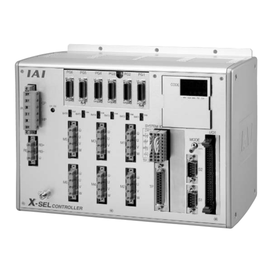
Part 1 Installation INTELLIGENT ACTUATOR Chapter 4 Name and Function of Each Part 1. Front View of Controller P Type (Standard Specification), 4 axes P Type (Standard Specification), 4 axes with expansion I/O board and brake unit... - Page 46 Part 1 Installation INTELLIGENT ACTUATOR Q Type (Global Specification), 4 axes Q Type (Global Specification), 4 axes with expansion I/O board and brake unit...
- Page 47 Part 1 Installation INTELLIGENT ACTUATOR (1) FG terminal This terminal is used to ground FG on the enclosure. The enclosure is connected to PE in the AC input part inside the controller. FG Terminal Specifications Item Description M4 3-point SEMS screw, 5 mm Name Cable size 2.0 to 5.5 mm...
- Page 48 Part 1 Installation INTELLIGENT ACTUATOR (3) AC-power input connector A 200-VAC, single-phase or three-phase input connector consisting of six terminals including motor power terminals, control power terminals and a PE terminal. Note) Take note that the single-phase input specification and three-phase input specification are available depending on the required motor- drive power source.
- Page 49 Part 1 Installation INTELLIGENT ACTUATOR (6) Encoder/axis-sensor This connector is used to connect the actuator encoder and axis sensors connector such as LS, CREEP and OT. * LS, CREEP and OT sensors are optional. Encoder/Axis-sensor Connector Specifications Item Description Details Half-pitch, 26-pin I/O 10226-6202JL (by Sumitomo Connector...
- Page 50 Note 1: The safety gate switch will not function if this switch is not set correctly. Note 2: Q type controllers connot be used with IAI’s standard teaching pendants. Note 3: The TP switch is not provided on Q type controllers.
- Page 51 Part 1 Installation INTELLIGENT ACTUATOR (9) Teaching connector The teaching interface connects IAI’s teaching pendant or a PC (PC software) to enable operation and setting of your equipment from the teaching pendant/PC. The physical interface consists of a RS232C system based on a 25-pin, D-sub connector. The signal level conforms to RS232C, and a desired baud rate (up to 115.2 kbps) can be selected...
- Page 52 Part 1 Installation INTELLIGENT ACTUATOR Interface Specifications of Teaching Serial Interface Item Direction Signal name Details Frame ground Transmitted data Received data Request to send Clear to send Equipment ready Signal ground Not connected RSV signal line for generic teaching RSVTBX1 pendant RSV signal line for generic teaching...
- Page 53 Part 1 Installation INTELLIGENT ACTUATOR (10) System I/O connector This I/O connector is used to control the safety actions of the controller. With the global specification, a safety circuit conforming to a desired safety category of up to level 4 can be configured using this connector and an external safety circuit.
- Page 54 Part 1 Installation INTELLIGENT ACTUATOR (11) Panel window This window consists of a 4-digit, 7-segment LED display and five LED lamps that indicate the status of the equipment. For the information shown on the display, refer to 2, “Explanation of Codes Displayed on the Panel Window”...
- Page 55 Part 1 Installation INTELLIGENT ACTUATOR I/O Interface List Pin No. Category Port No. Function Cable color +24-V input Brown-1 Program start Red-1 General-purpose input Orange-1 General-purpose input Yellow-1 The functions are at the time of General-purpose input Green-1 shipment. The functions assigned to port Nos.
- Page 56 Part 1 Installation INTELLIGENT ACTUATOR (14) General RS232C port Channel 1 of the two-channel RS232C port provided for connection of connector 1 general RS232C equipment. (Refer to I/O parameter Nos. 201 to 203.) (15) General RS232C port Channel 2 of the two-channel RS232C port provided for connection of connector 2 general RS232C equipment.
- Page 57 Part 1 Installation INTELLIGENT ACTUATOR (19) Brake-power input This connector is used to input the drive power for the actuator brake. 24 connector VDC must be supplied externally. If the specified brake power is not supplied, the actuator brake cannot be released. Be sure to supply the brake power for axes equipped with brake.
-
Page 58: Explanation Of Codes Displayed On The Panel Window
Part 1 Installation INTELLIGENT ACTUATOR 2. Explanation of Codes Displayed on the Panel Window Application Display Priority (*1) Description AC power is cut off (including momentary power failure or drop in power-source voltage). System-down level error Writing data to the flash ROM. Emergency stop is being actuated (except during the update mode). -
Page 59: Core
Part 1 Installation INTELLIGENT ACTUATOR Core Display Priority (*1) Description AC power is cut off (including momentary power failure or drop in power- source voltage). Cold-start level error Cold-start level error Operation-cancellation level error Operation-cancellation level error Message level error Message level error Application update mode Application update is in progress. -
Page 60: Current Monitor And Variable Monitor
Part 1 Installation INTELLIGENT ACTUATOR Current Monitor and Variable Monitor Other parameter Nos. 49 and 50 can be set up to monitor currents or variables on the panel window (main application version 0.09 or later). (1) Current monitor Currents of up to four axes having continuous axis numbers can be monitored. Parameter settings Other parameter No. - Page 61 Part 1 Installation INTELLIGENT ACTUATOR (2) Variable monitor The contents of global integer variables can be displayed on the panel window. Positive integers of 1 to 999 can be displayed. Parameter settings Other parameter No. 49 = 2 Other parameter No. 50 = Variable number of the global integer variable to be monitored When data is written to the flash ROM or a software reset (restart) is executed after the parameter values have been input, the panel window will show the content of the global integer variable, instead of “ready status”...
-
Page 62: Chapter 5 Specifications
15-bit incremental encoder (Wire-saving type) Position detection methods 15-bit rotation data backup absolute encoder Both have a control resolution of 14 bits (16384 pulses) For backup of absolute data: AB-5 by IAI Batteries For backup of system memory: CR2032 Speed setting 1 mm/sec to 3000 mm/sec (Varies depending on the model used.) - Page 63 RS232C port for teaching Enabled only in the manual operation mode. serial interface IAI’s dedicated teaching pendant or ANSI teaching pendant (selected by a switch) Dedicated 2-channel RS232C, 9-pin DTE specification RS232C port for general PC Half-duplex at speeds up to 115.2 kbps (1 channel) or up to 76.8 kbps...
-
Page 64: Q Type (Global Specification)
15-bit incremental encoder (Wire-saving type) Position detection methods 15-bit rotation data backup absolute encoder Both have a control resolution of 14 bits (16384 pulses) For backup of absolute data: AB-5 by IAI Batteries For backup of system memory: CR2032 Speed setting... -
Page 65: Differences Between Q Type (Global Specification) And P Type (Standard Specification)
RS232C port for teaching Enabled only in the manual operation mode. serial interface IAI’s dedicated teaching pendant or ANSI teaching pendant (selected by a switch) Dedicated 2-channel RS232C, 9-pin DTE specification RS232C port for general PC Half-duplex at speeds up to 115.2 kbps (1 channel) or up to 76.8 kbps... -
Page 66: External I/O Specifications
Caution If a non-contact circuit is connected externally, malfunction may result from leakage current. Use a circuit in which leakage current in a switch-off state does not exceed 1 mA. X-SEL controller’s input signal ON duration OFF duration At the default settings, the system recognizes the ON/OFF durations of input signals if they are approx. - Page 67 Part 1 Installation INTELLIGENT ACTUATOR (2) Output part External Output Specifications (NPN Specification) Item Specification Load voltage 24 VDC Maximum load current 100 mA per point, 400 mA per 8 ports Note) TD62084 (or equivalent) Leakage current 0.1 mA max. per point Insulation method Photocoupler insulation [1] Miniature relay...
-
Page 68: Pnp Specification
Caution If a non-contact circuit is connected externally, malfunction may result from leakage current. Use a circuit in which leakage current in a switch-off state does not exceed 1 mA. X-SEL controller’s input signal OFF duration ON duration At the default settings, the system recognizes the ON/OFF durations of input signals if they are approx. - Page 69 Part 1 Installation INTELLIGENT ACTUATOR (2) Output part External Output Specifications Item Specification Load voltage 24 VDC Maximum load current 100 mA per point, 400 mA per 8 ports Note) TD62784 (or equivalent) Leakage current 0.1 mA max. per point Insulation method Photocoupler insulation [1] Miniature relay...
-
Page 70: Power-Source Capacity And Heat Output
INTELLIGENT ACTUATOR 3. Power-Source Capacity and Heat Output The power consumption and heat output of the X-SEL controller will vary depending on the number of connected axes and I/O configuration. This section explains how to estimate the power-source capacity and heat output of your X-SEL controller. - Page 71 Part 1 Installation INTELLIGENT ACTUATOR Table 2. Motor Drive Powers and Output Losses (P/Q Types) Control power supply External power source Internal External Internal External Quantity consumption consumption consumption consumption [VA] [VA] [VA] [VA] Base part 31.4 Driver Per board 6.26 1 to 3 Encoder...
- Page 72 Actuator for axis 4: 60 W Standard controller with standard DIO Options: DeviceNet, teaching pendant (IAI’s standard type) [1] Control power-supply capacity {31.14 + 6.26 2 + (2.38 + 3.57) 4 + 4.57 4 + 5.95 1 + 2.38 + 3.57} 97.9 [VA]...
-
Page 73: External Dimensions
Part 1 Installation INTELLIGENT ACTUATOR 4. External Dimensions P/Q Type (Three-phase Standard Specification, Single-phase Global Specification, Single- phase Standard Specification) 4-axis Controller External views of enclosures for various 4-axis controllers are shown below (the external enclosure dimensions are the same for 1-axis to 4-axis controllers). Fig. - Page 74 Part 1 Installation INTELLIGENT ACTUATOR Fig. 4-3 P/Q Type 4-axis Controller with Expansion I/O Board (Incremental Specification) (Three-phase Standard Specification, Single-phase Global Specification, Single-phase Standard Specification) Fig. 4-4 P/Q Type 4-axis Controller with Expansion I/O Board + Absolute Brake Unit (Three-phase Standard Specification, Single-phase Global Specification, Single-phase Standard Specification)
-
Page 75: P/Q Type (Standard Specification) 6-Axis Controller (Three-Phase Standard Specification, Single-Phase Global Specification, Single-Phase Standard Specification)
Part 1 Installation INTELLIGENT ACTUATOR P/Q Type (Standard Specification) 6-axis Controller (Three-phase Standard Specification, Single-phase Global Specification, Single-phase Standard Specification) External views of enclosures for various 6-axis controllers are shown below (the external enclosure dimensions are the same for 5-axis and 6-axis controllers). Fig. - Page 76 Part 1 Installation INTELLIGENT ACTUATOR Fig. 4-7 P/Q Type 4-axis Controller with Expansion I/O Board (Incremental Specification) (Three-phase Standard Specification, Single-phase Global Specification, Single-phase Standard Specification) Fig. 4-8 P/Q Type 6-axis Controller with Expansion I/O Board + Absolute Brake Unit (Three-phase Standard Specification, Single-phase Global Specification, Single-phase Standard Specification)
-
Page 77: Q Type (Three-Phase Global Specification) 4-Axis Controller
Part 1 Installation INTELLIGENT ACTUATOR Q Type (Three-phase Global Specification) 4-axis Controller External views of enclosures for various 4-axis controllers are shown below (the external enclosure dimensions are the same for 1-axis to 4-axis controllers). Fig. 4-9 Q Type 4-axis Controller (Incremental Specification) (Three-phase Global Specification) Fig. - Page 78 Part 1 Installation INTELLIGENT ACTUATOR Fig. 4-11 Q Type 4-axis Controller with Expansion I/O Board (Incremental Specification) Fig. 4-12 Q Type 4-axis Controller with Expansion I/O Board + Absolute Brake Unit...
-
Page 79: Q Type (Three-Phase Global Specification) 6-Axis Controller
Part 1 Installation INTELLIGENT ACTUATOR Q Type (Three-phase Global Specification) 6-axis Controller External views of enclosures for various 6-axis controllers are shown below (the external enclosure dimensions are the same for 5-axis and 6-axis controllers). Fig. 4-13 Q Type 6-axis Controller (Incremental Specification) (Three-phase Global Specification) Fig. - Page 80 Part 1 Installation INTELLIGENT ACTUATOR Fig. 4-15 Q Type 6-axis Controller with Expansion I/O Board (Incremental Specification) (Three-phase Global Specification) Fig. 4-16 Q Type 6-axis Controller with Expansion I/O Board + Absolute Brake Unit (Three-phase Global Specification)
-
Page 81: Chapter 6 Safety Circuit
5. Applying voltage to the system I/Os The safety circuit of the X-SEL controller is designed to operate with 24 VDC. Therefore, never apply 100 or 200 VAC to the system I/Os. Doing so may damage the internal circuits of the controller. -
Page 82: Safety Circuit For P Type (Standard Specification) Controller
Set the teaching-pendant type switch located above the teaching connector to the position appropriate for the teaching pendant used. Set the switch to the left for an ANSI teaching pendant, or to the right for IAI’s standard teaching pendant. - Page 83 The RDYOUT contacts will close only when the controller has started properly. By connecting these contacts in series with similar contacts of other equipment, the soundness of the entire system can be checked easily. P type X-SEL controller External emergency-stop circuit Emergency-stop switch...
-
Page 84: Safety Circuit For Q Type (Global Specification) Controller
It is recommended that the control power supply be wired from the same power source as the motor power supply at a point before the drive-source cutoff part is connected. Please note that IAI is not liable for any losses arising from a malfunction of the safety circuit configured by the user. - Page 85 (DET) provides an input for detecting malfunction of the safety circuit (mainly fused relay contacts). Be sure to use this signal if you want the X-SEL controller to detect fused contacts. If the safety circuit is configured as a closed system to manage fused contacts and other problems independently, safety category 4 can be met without connecting this signal to the controller.
- Page 86 Part 1 Installation INTELLIGENT ACTUATOR EM1/EMG2, ENB1/ENB2 EMG1 (line+)/(line-) and EMG2 (line+)/(line-) are redundant emergency-stop control lines. ENB1 (line+)/(line-) and ENB2 (line+)/(line-) are redundant enabling control lines. Use these lines to cut off the external drive source. Since they are completely dry signal lines, configure a relay circuit using an external power source.
- Page 87 Part 1 Installation INTELLIGENT ACTUATOR Q Type X-SEL Controller Power supply part Digital control part Not installed External emergency-stop reset contact output AC cutoff relay DC bus Rectifier To power stage Power-on reset MPSDWN bit Teaching pendant Power error Mushroom emergency-...
- Page 88 Part 1 Installation INTELLIGENT ACTUATOR External Emergency-Stop Circuit 200-VAC, three- phase Relay Contactor (NEO SC) Contactor (NEO SC) Reset switch External emergency-stop switch External Safety relay unit EMG switch (G9SA-301 by Omron) contact 1 External EMG switch contact 2 Safety gate switch External SGATE contact 1...
-
Page 89: Safety Circuit Timing Charts For Q-Type Sel Controller
Part 1 Installation INTELLIGENT ACTUATOR 4. Safety Circuit Timing Charts for Q-type SEL Controller Safety circuit timing charts for Q-type SEL controller are shown below. The timings covered by the timing charts are as follows: [1], “Power on,” [2], “Emergency stop,” [3], “Power on during emergency stop,”... - Page 90 Part 1 Installation INTELLIGENT ACTUATOR [2] Emergency stop 200-VAC control power supply Successful startup of CPU I/O output signal: Port No. 301 Ready output Rdy (system I/O) SDN (system I/O) EMG1/EMG2 (system I/O) Emergency stop switch = ON Emergency stop switch = OFF ENB1/ENB2 (system I/O) Occurrence of secret level error Occurrence of message level error...
- Page 91 Part 1 Installation INTELLIGENT ACTUATOR [3] Power on during emergency stop 200-VAC control power supply Successful startup of CPU I/O output signal: Port No. 301 Ready output Rdy (system I/O) SDN (system I/O) EMG1/EMG2 (system I/O) Rdy and SDN turns ON due to a ENB1/ENB2 (system I/O) reset of the emergency stop.
- Page 92 Part 1 Installation INTELLIGENT ACTUATOR [4] Enable input 200-VAC control power supply Successful startup of CPU I/O output signal: Port No. 301 Ready output Rdy (system I/O) SDN (system I/O) EMG1/EMG2 (system I/O) Enable switch = ON Enable switch = OFF ENB1/ENB2 (system I/O) Occurrence of secret level error Occurrence of message level error...
- Page 93 Part 1 Installation INTELLIGENT ACTUATOR [5] System-shutdown level error 200-VAC control power supply Successful startup of CPU I/O output signal: Port No. 301 Ready output Rdy (system I/O) SDN (system I/O) EMG1/EMG2 (system I/O) ENB1/ENB2 (system I/O) Occurrence of secret level error Occurrence of message level error Occurrence of operation-cancellation level error Occurrence of cold-start level error...
- Page 94 Part 1 Installation INTELLIGENT ACTUATOR [6] Cold-start level error 200-VAC control power supply Successful startup of CPU I/O output signal: Port No. 301 Ready output Rdy (system I/O) The timings of SDN and Rdy vary slightly according to the nature of the error. SDN (system I/O) EMG1/EMG2 (system I/O) ENB1/ENB2 (system I/O)
- Page 95 Part 1 Installation INTELLIGENT ACTUATOR [7] Operation-cancellation level error 200-VAC control power supply Successful startup of CPU I/O output signal: Port No. 301 Ready output Rdy (system I/O) SDN (system I/O) EMG1/EMG2 (system I/O) ENB1/ENB2 (system I/O) Occurrence of secret level error Occurrence of message level error Occurrence of operation-cancellation level error Operation-cancellation level or lower...
- Page 96 Part 1 Installation INTELLIGENT ACTUATOR [8] Power ON (combined with drive-source cutoff reset input) 200-VAC control power supply Successful startup of CPU I/O input signal: Port No. 14 Drive-source cutoff reset input I/O output signal: Port No. 301 Ready output Rdy (system I/O) SDN (system I/O) EMG1/EMG2 (system I/O)
- Page 97 Part 1 Installation INTELLIGENT ACTUATOR [9] Emergency stop (combined with drive-source cutoff reset input) 200-VAC control power supply Successful startup of CPU I/O input signal: Port No. 14 Drive-source cutoff reset input I/O output signal: Port No. 301 Ready output Rdy (system I/O) SDN (system I/O) EMG1/EMG2 (system I/O)
-
Page 98: Chapter 7 System Setup
Note 2: When connecting a teaching pendant or PC cable (PC software), set the teaching-pendant type switch to an appropriate position. Left: ANSI teaching pendant or PC cable (conforming to safety category 4) Right: IAI’s standard teaching pendant or PC cable... -
Page 99: Connection Diagram For Q Type (Global Specification)
Part 1 Installation INTELLIGENT ACTUATOR Connection Diagram for Q Type (Global Specification) Single-phase specification CP: Single-phase, 200 to 230-VAC power source MP: Three-phase, 200 to 230-VAC power source Three-phase specification CP: Single-phase, 200 to 230-VAC power source MP: Three-phase, 200 to 230-VAC power source Absolute-data backup Auxiliary power battery enable/disable... -
Page 100: Startup Procedure
4. Set the teaching-pendant type switch. (Note 1) Q type controllers have no TP-SW. (Note 2) Q type controllers cannot be used with IAI’s standard teaching pendants or standard PC cables. Left: PC cable (conforming to safety category 4) SEL-T, SEL-TD, SEL-TG teaching pendant... -
Page 101: I/O Connection Diagram
Part 1 Installation INTELLIGENT ACTUATOR 2. I/O Connection Diagram NPN specification Pin No. Category Port No. Function (Note) +24-V input Program start General-purpose input General-purpose input General-purpose input General-purpose input General-purpose input General-purpose input Program specification (PRG No. 1) Program specification (PRG No. 2) Program specification (PRG No. -
Page 102: Pnp Specification
Part 1 Installation INTELLIGENT ACTUATOR PNP specification Pin No. Category Port No. Function +24-V input Program start General-purpose input General-purpose input General-purpose input General-purpose input General-purpose input General-purpose input Program specification (PRG No. 1) Program specification (PRG No. 2) Program specification (PRG No. 4) Program specification (PRG No. -
Page 103: I/O Flat Cable
Part 1 Installation INTELLIGENT ACTUATOR I/O Flat Cable Flat cable: KFX-50 (S) (Color) (Kaneko Cord) Connector not attached Flat cable (50 cores) Socket (with strain relief): XG4M-5030-T (Omron) Color Color Color Color Color Brown-1 Brown-2 Brown-3 Brown-4 Brown-5 Red-1 Red-2 Red-3 Red-4 Red-5... -
Page 104: Changing Port Numbers Assigned To I/O Function Selections (Main (From32M) Or Later)
300 (area 2) to 315 (area 2) whose functions have been set by I/O parameter Nos. 331 to 346, “Output function selection *** (area 2).” Note: The above functions are supported by X-SEL PC software of V7.2.0.0 or later. (1) Assignment example of input function selection Given below is an example of assigning input function selection 000 (program start) whose function has been set by I/O parameter No. - Page 105 Part 1 Installation INTELLIGENT ACTUATOR (2) Assignment example of output function selection Given below is an example of assigning output function selection 300 (error output) whose function has been set by I/O parameter No. 46, “Output function selection 300,” to a different output port. Use I/O parameter No.
- Page 106 Part 1 Installation INTELLIGENT ACTUATOR (4) Use example Given below is a setting example of system I/O assignments: Input port No. 16 = Program start signal (ON edge) (BCD specification) Input port No. 17 = Servo ON signal Input port Nos. 18 to 23 = Program number specified for program start Input port No.
-
Page 107: Multi-Point Dio Board
Part 1 Installation INTELLIGENT ACTUATOR 3. Multi-point DIO Board This board is a multi-point DIO board equipped with 48 input points and 48 output points for use with XSEL controllers. Overview 3.1.1 Features [1] One board provides a total of 96 input/output points. Multiple inputs/outputs of your XSEL controller can be controlled with a single board offering 48 input points and 48 output points. -
Page 108: External Interface Specifications
Part 1 Installation INTELLIGENT ACTUATOR External Interface Specifications 3.3.1 Terminal Assignment for External DIO Interface Overview of multi-point DIO interface specifications Item Overview Remarks Applicable connector Half-pitch flat connector, 100 pins HIF6-100PA-1.27DS (Hirose) Connector name External DIO connector DC24V 10% External power supply The power line is divided into two circuits, each supplying power to a group of 24 DI... -
Page 109: Connection Cables For Multi-Point Io Board
Part 1 Installation INTELLIGENT ACTUATOR Connection Cables for Multi-point IO Board Cable 1 Cable 2 Port Category Color Function Category Pin No. Color Port No. Function External power supply 24 VDC Brown-1 Brown-1 Alarm output for pin Nos. 2 to 25/51 to 74 Red-1 Program start Red-1... -
Page 110: Connection Cables For Multi-Point Io Board
Part 1 Installation INTELLIGENT ACTUATOR Connection Cables for Multi-point IO Board Model: CB-X-PIOH020 Open end without connector Flat cable (50 cores) UL2651 AWG28x2 Socket: HIF6-100D-1.27R (Hirose) Cable 1 (pins 1 to 50) Cable 2 (pins 51 to 100) -
Page 111: Input/Output Circuits
Part 1 Installation INTELLIGENT ACTUATOR Input/Output Circuits 3.6.1 Input Input specifications Item Specification (Common to PNP/NPN specifications) DC24V 10% External power-supply voltage Input current 7 mA max. per point Leak current 1 mA max. per point Input circuit NPN specification External power supply Internal circuit Input terminal... - Page 112 Part 1 Installation INTELLIGENT ACTUATOR 3.6.2 Output Output specifications Item Specification Output element Transistor array NPN specification: TD62084AF by Toshiba Corporation PNP specification: TD62784AF by Toshiba Corporation DC24 10% External power-supply voltage Maximum load current 50 mA max. per point (400 mA max.
-
Page 113: Chapter 8 How To Perform An Absolute Encoder Reset (Absolute Specification)
(3) All adjustments other than the absolute reset must have been completed. Procedure (1) Turn off the X-SEL Controller power. Turn on the PC power and wait for the operating system to be started. (2) Connect the 9-pin, D-sub connector on one end of the connection cable to the communication port on the PC, and connect the 25-pin, D-sub connector on the other end to the 25-pin communication port on the controller. - Page 114 Part 1 Installation INTELLIGENT ACTUATOR (6) The X-SEL PC software window will be displayed. Clicking the [OK] button will clear the error message. (7) From the [Monitor (M)] menu, select [Detailed Error Information (E)] to check the current error status.
- Page 115 Part 1 Installation INTELLIGENT ACTUATOR (8) From the [Controller (C)] menu, select [Absolute Reset (A)]. (9) When a [Warning] dialog box is displayed, click the [OK] button. (10) The [Abs. Encoder Reset] dialog box will be displayed. Click here to select the axis you wish to perform an absolute reset for. (11) Clicking the [Encoder Rotation Data Reset 1] button will display a [Warning] dialog box.
- Page 116 Part 1 Installation INTELLIGENT ACTUATOR (12) Another [Warning] dialog box will be displayed. Click the [Yes] button. (13) When the processing of “encoder rotation data reset 1” is complete, the red arrow will move to the next item. Press the following processing buttons one by one (the red arrow will move to the next item when each process is completed): 1.
- Page 117 (16) If no other error is present, the controller’s 7-segment LED display will show “rdy.” (17) This completes the absolute encoder reset. To redo the absolute encoder reset, exit the X-SEL PC software and repeat the procedure from the beginning.
-
Page 118: How To Perform Absolute Reset On Zr Unit (Absolute Type Only)
Part 1 Installation INTELLIGENT ACTUATOR 2. How to Perform Absolute Reset on ZR Unit (Absolute Type Only) Under certain conditions such as when the ZR unit is connected to the controller for the first time, absolute encoder battery voltage is abnormal, or encoder cable has been disconnected, an encoder battery error will generate and absolute reset will be required. -
Page 119: Starting The Absolute Reset Menu (Ball-Screw Spline Adjustment Window)
Part 1 Installation INTELLIGENT ACTUATOR Starting the Absolute Reset Menu (Ball-screw Spline Adjustment Window) (1) Start the ball-screw spline adjustment window from the PC software. (2) The ball-screw spline adjustment window starts. When a linear movement axis number is selected, “Rotational Movement Axis Number (Mating Axis Number)”... -
Page 120: Absolute Reset (Ball-Screw Spline Adjustment) Procedure
Part 1 Installation INTELLIGENT ACTUATOR Absolute Reset (Ball-screw Spline Adjustment) Procedure (1) Select a “linear movement axis number” which will be used to perform an absolute reset (ball-screw spline adjustment). (2) Click the [Reset Encoder Multi-rotation Data 1 (Linear Movement Axis, Rotational Movement Axis)] button. - Page 121 Part 1 Installation INTELLIGENT ACTUATOR (3) When the dialog box appears, click the [Yes (Y)] button. (4) When the dialog box appears, click the [Yes (Y)] button.
- Page 122 Part 1 Installation INTELLIGENT ACTUATOR (5) Click the [Reset Controller Error] button. (6) Click the [Servo ON (Linear Movement Axis, Rotational Movement Axis)] button.
- Page 123 Part 1 Installation INTELLIGENT ACTUATOR (7) Click the [Stand By in Tentative Reference Posture (Linear Movement Axis)] button. Be careful because the linear movement axis (Z-axis) returns to its home. (8) Jog the rotational movement axis (R-axis) to the reference posture position (refer to the illustration of reference posture), and then click the [End Jogging] button.
- Page 124 Part 1 Installation INTELLIGENT ACTUATOR (9) Click the [Servo OFF (Linear Movement Axis, Rotational Movement Axis)] button. (10) Press the emergency stop switch (emergency stop button on the PC cable). (11) Release the brake. Release the brake using the switch on the controller side.
- Page 125 Part 1 Installation INTELLIGENT ACTUATOR (12) Set the plate and pin constituting the adjustment jig, as shown below, to affix the robot in the reference posture. D-cut surface Shaft Installation method [1] Insert the ball-screw spline into the hole in the jig from below. [2] Cause the D-cut surface of the ball-screw spline to contact the surface a.
- Page 126 Part 1 Installation INTELLIGENT ACTUATOR (13) Click the [Confirm] button. (14) Click the [Reset Encoder Multi-rotation Data 2 (Rotational Movement Axis)] button.
- Page 127 Part 1 Installation INTELLIGENT ACTUATOR (15) When the dialog box appears, click the [Yes (Y)] button. (16) When the dialog box appears, click the [Yes (Y)] button.
- Page 128 Part 1 Installation INTELLIGENT ACTUATOR (17) Click the [Automatically Refresh Home Preset Value (Required) (Rotational Movement Axis)] button. (18) Remove the adjustment jig. (19) Lock the brake (on the front panel of the controller). (20) Cancel the emergency stop (by releasing the emergency stop button on the PC cable). (21) Click the [Confirm] button.
- Page 129 Part 1 Installation INTELLIGENT ACTUATOR (22) Click the [Servo ON (Linear Movement Axis, Rotational Movement Axis)] button. (23) Click the [Stand By in Tentative Reference Posture (Linear Movement Axis) (Rotational Movement Axis 0)] button. Be careful because the rotational movement axis (R-axis) moves to the zero point and then the linear movement axis (Z-axis) returns to its home.
- Page 130 Part 1 Installation INTELLIGENT ACTUATOR (24) Click the [Servo OFF (Linear Movement Axis, Rotational Movement Axis)] button. (25) Click the [Reset Encoder Multi-rotation Data 3 (Linear Movement Axis)] button.
- Page 131 Part 1 Installation INTELLIGENT ACTUATOR (26) When the dialog box appears, click the [Yes (Y)] button. (27) Click the [Automatically Refresh Home Preset Value (Required) (Linear Movement Axis)] button, and then click “X” in the top right-hand corner of the window to close the window. Warning ...
- Page 132 Part 1 Installation INTELLIGENT ACTUATOR (28) Closing the ball-screw spline adjustment window following the ball-screw spline adjustment opens the following screen. Click the [Yes] button. (29) When all data has been written to the flash ROM, the following screen appears. Click the [Yes] button.
-
Page 133: Chapter 9 Maintenance
Cables System-memory backup battery: CR2032 (Note 1) --- Must be replaced after approx. 1.5 years* (Note 2) Absolute-data backup battery: AB-5 by IAI --- Must be replaced after approx. 2 years* (Note 2) (Absolute specification) Fuses (Note 1) CR2032 is a standardized product and can be used with products by any manufacture. -
Page 134: Replacement Procedure For System-Memory Backup Battery
Backing up the system memory If “Other parameter No. 20, Backup-battery installation function type” is set to “2” (installed), the following SRAM data in the X-SEL Controller will be backed up by the system-memory backup battery on the panel board: ... - Page 135 Part 1 Installation INTELLIGENT ACTUATOR Battery Replacement Procedure 1) Remove the 7-segment LED panel from the controller. Slide the panel upward and pull it toward you to remove. 2) Press the center of the battery using a finger, as shown. The battery will come off from the holder. 3) Install a new battery into the holder.
- Page 136 Part 1 Installation INTELLIGENT ACTUATOR (8) When the replacement of system-memory backup battery is complete, confirm that the battery is installed securely and then turn on the controller power. (9) Revert “Other parameter No. 20, Backup-battery installation function type” to the value recorded in step 2, transfer the setting to the controller, and then perform a flash ROM write.
-
Page 137: Replacement Procedure For Absolute-Data Backup Battery
Part 1 Installation INTELLIGENT ACTUATOR 4. Replacement Procedure for Absolute-Data Backup Battery The replacement procedure will vary depending on if errors are present at the time of replacement and if so, which errors are present (No.A23, 914, CA2). If no error is present, perform steps (1) to (8). ... - Page 138 Part 1 Installation INTELLIGENT ACTUATOR (6) Turn on the controller power. (7) Set the absolute-data backup battery enable/disable switch to the top (ENB) position. (Note) This operation is not required if no error has generated or when an A23 error has generated. (8) Turn off the controller power and install the brake switch panel with the screws.
-
Page 139: Part 2 Operation
Chapter 1 Operation How to Start a Program With the X-SEL Controller, the stored programs can be started (run) using four methods. Of these methods, two are mainly used to debug programs or perform trial operations, while the remaining two are used in general applications on site. -
Page 140: Starting A Program By Auto-Start Via Parameter Setting
Part 2 Operation INTELLIGENT ACTUATOR 1. Starting a Program by Auto-Start via Parameter Setting I/O parameter No. 33 (input function selection 003) = 1 (default factory setting) This parameter is set using the teaching pendant or PC software. Set the number of the program you wish to start automatically in other parameter No. -
Page 141: Starting Via External Signal Selection
Part 2 Operation INTELLIGENT ACTUATOR 2. Starting via External Signal Selection Select a desired program number externally and then input a start signal. (1) Flow chart Controller External device Power ON Power ON When the READY signal turns ON, the Ready output RDY lamp (green) on the controller READY signal... - Page 142 Part 2 Operation INTELLIGENT ACTUATOR (2) Timing chart [1] Program start Duration after the ready output turns ON until input of external start signal is permitted Ready output T1 = 10 msec min. Program 1 Program 2 Duration after the program number is input until Program input of external start signal is permitted number input...
-
Page 143: Drive-Source Recovery Request And Operation-Pause Reset Request
Part 2 Operation INTELLIGENT ACTUATOR 3. Drive-Source Recovery Request and Operation-Pause Reset Request (1) Drive-source recovery request How to request a drive-source recovery A drive-source recovery request can be issued using one of the following methods: Set I/O parameter No. 44 to “1” (Input selection function 014 = Drive-source cutoff reset input), then input the ON edge to input port No. -
Page 144: Part 3 Controller Data Structure
Part 3 Controller Data Structure INTELLIGENT ACTUATOR Part 3 Controller Data Structure The controller data consists of parameters as well as position data and application programs used to implement SEL language. X-SEL Controller Data Structure Main Driver Driver Driver Driver... -
Page 145: Chapter 1 How To Save Data
INTELLIGENT ACTUATOR Chapter 1 How to Save Data Since the X-SEL Controller uses flash memory, some data are saved by battery backup while others are saved in the flash memory. When data is transferred from the PC software or teaching pendant to the controller, the data is only written to the main CPU memory as shown in the diagram below and will be erased once the controller is powered down or reset. -
Page 146: Controller With Expanded Memory (With Gateway Function)
Main CPU flash memory Write to flash memory Programs Parameters (other than Transfer upon reset slave parameters) Transfer Symbols Position (X-SEL axes) (Nos. 10001 to 20000) Write to flash memory Transfer Slave card Transfer upon reset parameters (variable driver parameters) -
Page 147: When The System-Memory Backup Battery Is Not Used
Part 3 Controller Data Structure INTELLIGENT ACTUATOR 2. When the System-Memory Backup Battery is Not Used Controller without Expanded Memory Other parameter No. 20 = 0 (System-memory backup battery not installed) Data will be retained while Data edited on the PC Data will be retained even after the power is on and cleared or teaching pendant... -
Page 148: Controller With Expanded Memory (With Gateway Function)
Main CPU flash memory Programs Parameters (other than Write to flash memory slave parameters) Transfer Symbols Transfer upon reset Position (X-SEL axes) (Nos. 1 to 20000) Write to flash memory User-data backup Transfer memory Transfer upon reset (Positions (RC axes)) -
Page 149: Points To Note
Part 3 Controller Data Structure INTELLIGENT ACTUATOR 3. Points to Note Point to note when transferring data and writing to the flash memory Never turn off the main power while data is being transferred or written to the flash memory. The data will be lost and the controller operation may be disabled. Point to note when saving parameters to a file The encoder parameters are stored in the EEPROM of the actuator’s encoder itself (unlike other parameters, they are not stored in the EEPROM of the controller). - Page 150 Part 3 Controller Data Structure INTELLIGENT ACTUATOR Note on increased number of parameters On a controller with expanded memory (with gateway function), the number of parameters has increased. Number of parameters Without expanded memory With expanded memory All-axis Axis-specific Driver Encoder I/O device Other...
-
Page 151: Chapter 2 X-Sel Language Data
Part 3 Controller Data Structure INTELLIGENT ACTUATOR Chapter 2 X-SEL Language Data 1. Values and Symbols Used in SEL Language List of Values and Symbols Used The various functions required in a program are represented by values and symbols. Function... -
Page 152: I/O Ports
Integers and real numbers can be used. However, pay due attention to the following limitations: Numeric data The X-SEL Controller can handle values of maximum eight digits including a sign and a decimal point. Integer: -9,999,999 to 99,999,999 Real number: Maximum eight digits including a sign and decimal point, regardless of the size of value Example) 999999.9, 0.123456, -0.12345... -
Page 153: Virtual I/O Ports
Part 3 Controller Data Structure INTELLIGENT ACTUATOR Virtual I/O Ports (1) Virtual input ports Port No. Function 7000 Always OFF 7001 Always ON 7002 Voltage low warning for system-memory backup battery 7003 Abnormal voltage of system-memory backup battery 7004 (For future expansion = Use strictly prohibited) 7005 (For future expansion = Use strictly prohibited) 7006... - Page 154 Part 3 Controller Data Structure INTELLIGENT ACTUATOR (2) Virtual output ports Port No. Function Latch cancellation output for a latch signal indicating that all-operation-cancellation factor is present 7300 (7011) (latch is cancelled only when operation-cancellation factor is no longer present) (7300 will be turned OFF following an attempt to cancel latch.) 7301 to 7380 (For future expansion = Use strictly prohibited)
-
Page 155: Flags
Part 3 Controller Data Structure INTELLIGENT ACTUATOR Flags Contrary to its common meaning, the term “flag” as used in programming means “memory.” Flags are used to set or reset data. They correspond to “auxiliary relays” in a sequencer. Flags are divided into global flags (Nos. 600 to 899) that can be used in all programs, and local flags (Nos. 900 to 999) that can be used only in each program. -
Page 156: Variables
Part 3 Controller Data Structure INTELLIGENT ACTUATOR Variables (1) Meaning of variable “Variable” is a technical term used in software programming. Simply put, it means “a box in which a value is put.” Variables can be used in many ways, such as putting in or taking out a value and performing addition or subtraction. - Page 157 Part 3 Controller Data Structure INTELLIGENT ACTUATOR (2) Types of variables Variables are classified into two types, as follows: Integer variables These variables cannot handle decimal places. [Example] 1234 Integer variable box Variable box 1 1 2 3 4 200 to 299 Integer variable number Can be used in all programs “Global integer variables”...
- Page 158 Part 3 Controller Data Structure INTELLIGENT ACTUATOR Variables with “*” (asterisk) (indirect specification) An “*” (asterisk) is used to specify a variable. In the following example, the content of variable box 1 will be put in variable box 2. If variable box 1 contains “1234,”...
-
Page 159: Tags
Part 3 Controller Data Structure INTELLIGENT ACTUATOR Tags The term “tag” means “heading.” Tags are used in the same way you attach labels to the pages in a book you want to reference frequently. A tag is a destination specified in a jump command “GOTO.” Command Operand 1 Tag number (Integer between 1 and 99) -
Page 160: Subroutines
Part 3 Controller Data Structure INTELLIGENT ACTUATOR Subroutines By taking out the parts of a program that are used repeatedly and registering them as “subroutines,” the same processing can be performed with fewer steps. (A maximum of 15 nests are accommodated.) They are used only in each program. -
Page 161: Symbols
INTELLIGENT ACTUATOR Symbols In the X-SEL Controller, values such as variable numbers and flag numbers can be handled as symbols. For the method to edit symbols, refer to “Editing Symbols” in the operation manual for X-SEL teaching pendant or “Symbol Edit Window” in the operation manual for X-SEL PC software. -
Page 162: Axis Specification
Part 3 Controller Data Structure INTELLIGENT ACTUATOR 1.10 Axis Specification Axes can be specified based on axis number or axis pattern. (1) Axis numbers and how axes are stated Each of multiple axes is stated as follows: Axis number How axis is stated Axis 1 Axis 2 Axis 3... - Page 163 Part 3 Controller Data Structure INTELLIGENT ACTUATOR (2) Axis pattern Whether or not each axis will be used is indicated by “1” or “0.” (Upper) (Lower) Axis Axis 6 Axis 5 Axis 4 Axis 3 Axis 2 Axis 1 number Used Not used [Example] When axes 1 and 2 are used...
-
Page 164: Position Part
Part 3 Controller Data Structure INTELLIGENT ACTUATOR X-SEL language consists of a position part (position data = coordinates, etc.) and a command part (application program). 2. Position Part As position data, coordinates, speeds, accelerations and decelerations are set and stored. -
Page 165: Command Part
Part 3 Controller Data Structure INTELLIGENT ACTUATOR 3. Command Part The primary feature of SEL language is its very simple command structure. Since the structure is simple, there is no need for a compiler (to translate into computer language) and high-speed operation is possible via an interpreter (the program runs as commands are translated). -
Page 166: Extension Condition
Part 3 Controller Data Structure INTELLIGENT ACTUATOR Extension Condition Conditions can be combined in a complex manner. (SEL language) AND extension (Ladder diagram) Command Input Extension Condition Output condition Operand Operand condition Command Condition 1 Condition 2 Condition Operand Operand Condition 3 Command Condition OR extension... -
Page 167: Part 4 Commands
Part 4 Commands INTELLIGENT ACTUATOR Part 4 Commands Chapter 1 List of SEL Language Command Codes 1. By Function Variables can be specified indirectly in the operand 1, operand 2 and output fields. Symbols can be input in the condition, operand 1, operand 2 and output fields. The input items in ( ) under operand 1 and operand 2 are optional. - Page 168 Part 4 Commands INTELLIGENT ACTUATOR Operation type in the output field CC: Command was executed successfully, ZR: Operation result is zero, PE: Operation is complete, CP: Command part has passed, TU: Time up EQ: Operand 1 = Operand 2, NE: Operand 1 Operand 2, GT: Operand 1 >...
- Page 169 Part 4 Commands INTELLIGENT ACTUATOR Operation type in the output field CC: Command was executed successfully, ZR: Operation result is zero, PE: Operation is complete, CP: Command part has passed, TU: Time up EQ: Operand 1 = Operand 2, NE: Operand 1 Operand 2, GT: Operand 1 >...
- Page 170 Part 4 Commands INTELLIGENT ACTUATOR Operation type in the output field CC: Command was executed successfully, ZR: Operation result is zero, PE: Operation is complete, CP: Command part has passed, TU: Time up EQ: Operand 1 = Operand 2, NE: Operand 1 Operand 2, GT: Operand 1 >...
- Page 171 Part 4 Commands INTELLIGENT ACTUATOR Operation type in the output field CC: Command was executed successfully, ZR: Operation result is zero, PE: Operation is complete, CP: Command part has passed, TU: Time up EQ: Operand 1 = Operand 2, NE: Operand 1 Operand 2, GT: Operand 1 >...
-
Page 172: Alphabetical Order
Part 4 Commands INTELLIGENT ACTUATOR 2. Alphabetical Order Operation type in the output field EQ: Operand 1 = Operand 2, NE: Operand 1 Operand 2, CC: Command was executed successfully, GT: Operand 1 > Operand 2, GE: Operand 1 Operand 2, Operation result is zero, PE: Operation is complete, Operand 1 <... - Page 173 Part 4 Commands INTELLIGENT ACTUATOR Operation type in the output field CC: Command was executed successfully, ZR: Operation result is zero, Operation is complete, CP: Command part has passed, TU: Time up EQ: Operand 1 = Operand 2, NE: Operand 1 Operand 2, GT: Operand 1 >...
- Page 174 Part 4 Commands INTELLIGENT ACTUATOR Operation type in the output field CC: Command was executed successfully, ZR: Operation result is zero, Operation is complete, CP: Command part has passed, TU: Time up EQ: Operand 1 = Operand 2, NE: Operand 1 Operand 2, GT: Operand 1 >...
- Page 175 Part 4 Commands INTELLIGENT ACTUATOR Operation type in the output field CC: Command was executed successfully, ZR: Operation result is zero, Operation is complete, CP: Command part has passed, TU: Time up EQ: Operand 1 = Operand 2, NE: Operand 1 Operand 2, GT: Operand 1 >...
- Page 176 Part 4 Commands INTELLIGENT ACTUATOR Operation type in the output field CC: Command was executed successfully, ZR: Operation result is zero, Operation is complete, CP: Command part has passed, TU: Time up EQ: Operand 1 = Operand 2, NE: Operand 1 Operand 2, GT: Operand 1 >...
- Page 177 Part 4 Commands INTELLIGENT ACTUATOR RC Gateway Function Commands (Controller with Gateway Function Only) For commands relating to the RC gateway function, refer to the “Operation Manual for X-SEL Controller P/Q/PX/QX RC Gateway Function.” Operation type in the output field EQ: Operand 1 = Operand 2, NE: Operand 1 ...
-
Page 178: Chapter 2 Explanation Of Commands
Part 4 Commands INTELLIGENT ACTUATOR Chapter 2 Explanation of Commands 1. Commands Variable Assignment LET (Assign) Command, declaration Extension condition Input condition Output Command, (LD, A, O, AB, OB) (I/O, flag) Operand 1 Operand 2 (Output, flag) declaration Variable Optional Optional Data... - Page 179 Part 4 Commands INTELLIGENT ACTUATOR CLR (Clear variable) Command, declaration Extension condition Input condition Output Command, (LD, A, O, AB, OB) (I/O, flag) (Output, flag) Operand 1 Operand 2 declaration Variable Variable Optional Optional number number [Function] Clear the variables from the one specified in operand 1 through the other specified in operand 2.
-
Page 180: Arithmetic Operation
Part 4 Commands INTELLIGENT ACTUATOR Arithmetic Operation ADD (Add) Command, declaration Extension condition Input condition Output Command, (LD, A, O, AB, OB) (I/O, flag) (Output, flag) Operand 1 Operand 2 declaration Variable Optional Optional Data number [Function] Add the content of the variable specified in operand 1 and the value specified in operand 2, and assign the result to the variable specified in operand 1. - Page 181 Part 4 Commands INTELLIGENT ACTUATOR MULT (Multiply) Command, declaration Extension condition Input condition Output Command, (LD, A, O, AB, OB) (I/O, flag) (Output, flag) Operand 1 Operand 2 declaration Variable Optional Optional MULT Data number [Function] Multiply the content of the variable specified in operand 1 by the value specified in operand 2, and assign the result to the variable specified in operand 1.
- Page 182 Part 4 Commands INTELLIGENT ACTUATOR MOD (Remainder of division) Command, declaration Extension condition Input condition Output Command, (LD, A, O, AB, OB) (I/O, flag) (Output, flag) Operand 1 Operand 2 declaration Variable Optional Optional Data number [Function] Assign, to the variable specified in 1, the remainder obtained by dividing the content of the variable specified in operand 1 by the value specified in operand 2.
-
Page 183: Function Operation
Part 4 Commands INTELLIGENT ACTUATOR Function Operation SIN (Sine operation) Command, declaration Extension condition Input condition Output Command, (LD, A, O, AB, OB) (I/O, flag) (Output, flag) Operand 1 Operand 2 declaration Variable Optional Optional Data number [Function] Assign the sine of the data specified in operand 2 to the variable specified in operand 1. The output will turn ON when the operation result becomes 0. - Page 184 Part 4 Commands INTELLIGENT ACTUATOR TAN (Tangent operation) Command, declaration Extension condition Input condition Output Command, (LD, A, O, AB, OB) (I/O, flag) (Output, flag) Operand 1 Operand 2 declaration Variable Optional Optional Data number [Function] Assign the tangent of the data specified in operand 2 to the variable specified in operand 1. The output will turn ON when the operation result becomes 0.
- Page 185 Part 4 Commands INTELLIGENT ACTUATOR SQR (Root operation) Command, declaration Extension condition Input condition Output Command, (LD, A, O, AB, OB) (I/O, flag) (Output, flag) Operand 1 Operand 2 declaration Variable Optional Optional Data number [Function] Assign the root of the data specified in operand 2 to the variable specified in operand 1. The output will turn ON when the operation result becomes 0.
-
Page 186: Logical Operation
Part 4 Commands INTELLIGENT ACTUATOR Logical Operation AND (Logical AND) Command, declaration Extension condition Input condition Output Command, (LD, A, O, AB, OB) (I/O, flag) (Output, flag) Operand 1 Operand 2 declaration Variable Optional Optional Data number [Function] Assign the logical AND operation result of the content of the variable specified in operand 1 and the value specified in operand 2, to the variable specified in operand 1. - Page 187 Part 4 Commands INTELLIGENT ACTUATOR OR (Logical OR) Command, declaration Extension condition Input condition Output Command, (LD, A, O, AB, OB) (I/O, flag) (Output, flag) Operand 1 Operand 2 declaration Variable Optional Optional Data number [Function] Assign the logical OR operation result of the content of the variable specified in operand 1 and the value specified in operand 2, to the variable specified in operand 1.
- Page 188 Part 4 Commands INTELLIGENT ACTUATOR EOR (Logical exclusive-OR) Command, declaration Extension condition Input condition Output Command, (LD, A, O, AB, OB) (I/O, flag) (Output, flag) Operand 1 Operand 2 declaration Variable Optional Optional Data number [Function] Assign the logical exclusive-OR operation result of the content of the variable specified in operand 1 and the value specified in operand 2, to the variable specified in operand 1.
-
Page 189: Comparison Operation
Part 4 Commands INTELLIGENT ACTUATOR Comparison Operation CP (Compare) Command, declaration Extension condition Input condition Output Command, (LD, A, O, AB, OB) (I/O, flag) (Output, flag) Operand 1 Operand 2 declaration Variable Optional Optional CP Data number [Function] The output will be turned ON if the comparison result of the content of the variable specified in operand 1 and the value specified in operand 2 satisfies the condition. -
Page 190: Timer
Part 4 Commands INTELLIGENT ACTUATOR Timer TIMW (Timer) Command, declaration Extension condition Input condition Output Command, (LD, A, O, AB, OB) (I/O, flag) (Output, flag) Operand 1 Operand 2 declaration Optional Optional TIMW Time Prohibited [Function] Stop the program and wait for the time specified in operand 1. The setting range is 0.01 to 99, and the unit is second. - Page 191 Part 4 Commands INTELLIGENT ACTUATOR TIMC (Cancel timer) Command, declaration Extension condition Input condition Output Command, (LD, A, O, AB, OB) (I/O, flag) (Output, flag) Operand 1 Operand 2 declaration Program Optional Optional TIMC Prohibited number [Function] Cancel a timer in other program running in parallel. (Note) Timers in TIMW, WTON, WTOF and READ commands can be cancelled.
- Page 192 Part 4 Commands INTELLIGENT ACTUATOR GTTM (Get time) Command, declaration Extension condition Input condition Output Command, (LD, A, O, AB, OB) (I/O, flag) (Output, flag) Operand 1 Operand 2 declaration Variable Optional Optional GTTM Prohibited number [Function] Read system time to the variable specified in operand 1. The time is specified in units of 10 milliseconds.
-
Page 193: I/O, Flag Operation
Part 4 Commands INTELLIGENT ACTUATOR I/O, Flag Operation BT (Output port, flag operation) Command, declaration Extension condition Input condition Output Command, (LD, A, O, AB, OB) (I/O, flag) (Output, flag) Operand 1 Operand 2 declaration (Output, Optional Optional BT Output, flag flag) [Function]... - Page 194 Part 4 Commands INTELLIGENT ACTUATOR BTPN (Output ON pulse) Command, declaration Extension condition Input condition Output Command, (LD, A, O, AB, OB) (I/O, flag) (Output, flag) Operand 1 Operand 2 declaration Output Timer Optional Optional BTPN port, flag setting [Function] Turn ON the specified output port or flag for the specified time.
- Page 195 Part 4 Commands INTELLIGENT ACTUATOR BTPF (Output OFF pulse) Command, declaration Extension condition Input condition Output Command, (LD, A, O, AB, OB) (I/O, flag) (Output, flag) Operand 1 Operand 2 declaration Output Timer Optional Optional BTPF port, flag setting [Function] Turn OFF the specified output port or flag for the specified time.
- Page 196 Part 4 Commands INTELLIGENT ACTUATOR WT (Wait for I/O port, flag) Command, declaration Extension condition Input condition Output Command, (LD, A, O, AB, OB) (I/O, flag) (Output, flag) Operand 1 Operand 2 declaration Optional Optional WT I/O, flag (Time) [Function] Wait for the I/O port or flag specified in operand 1 to turn ON/OFF.
- Page 197 Part 4 Commands INTELLIGENT ACTUATOR IN (Read I/O, flag as binary) Command, declaration Extension condition Input condition Output Command, (LD, A, O, AB, OB) (I/O, flag) (Output, flag) Operand 1 Operand 2 declaration Optional Optional I/O, flag I/O, flag [Function] Read the I/O ports or flags from the one specified in operand 1 through the other specified in operand 2, to variable 99 as a binary.
- Page 198 Part 4 Commands INTELLIGENT ACTUATOR INB (Read I/O, flag as BCD) Command, declaration Extension condition Input condition Output Command, (LD, A, O, AB, OB) (I/O, flag) (Output, flag) Operand 1 Operand 2 declaration Optional Optional I/O, flag BCD digits [Function] Read the I/O ports or flags from the one specified in operand 1 for the number of digits specified in operand 2, to variable 99 as a BCD.
- Page 199 Part 4 Commands INTELLIGENT ACTUATOR OUT (Write output, flag as binary) Command, declaration Extension condition Input condition Output Command, (LD, A, O, AB, OB) (I/O, flag) (Output, flag) Operand 1 Operand 2 declaration Optional Optional Output, flag Output, flag [Function] Write the value in variable 99 to the output ports or flags from the one specified in operand 1 through the other specified in operand 2.
- Page 200 Part 4 Commands INTELLIGENT ACTUATOR OUTB (Write output, flag as BCD) Command, declaration Extension condition Input condition Output Command, (LD, A, O, AB, OB) (I/O, flag) (Output, flag) Operand 1 Operand 2 declaration Optional Optional OUTB Output, flag BCD digits [Function] Write the value in variable 99 to the output ports or flags from the one specified in operand 1 for the number of digits specified in operand 2 as a BCD.
- Page 201 Part 4 Commands INTELLIGENT ACTUATOR FMIO (Set IN, INB, OUT, OUTB command format) Command, declaration Extension condition Input condition Output Command, (LD, A, O, AB, OB) (I/O, flag) Operand 1 Operand 2 (Output, flag) declaration Format Optional Optional FMIO Prohibited type [Function]...
- Page 202 Part 4 Commands INTELLIGENT ACTUATOR (4) Operand 1 = 3 Data is read or written after its upper 16 bits and lower 16 bits are reversed every 32 bits and its upper eight bits and lower eight bits are reversed every 16 bits. (I/O, flag number upper) (I/O, flag number lower) 01234567h ...
- Page 203 Part 4 Commands INTELLIGENT ACTUATOR [Example 2] Variable 99 = 00001234h (Decimal: 4660, BCD: 1234) OUT(B) command 00001234h Variable 99 4660 (IN/OUT command) 1234 (INB/OUTB command) IN(B) command OUT(B) command IN(B) command (I/O, flag number upper) (I/O, flag number lower) ...
-
Page 204: Program Control
Part 4 Commands INTELLIGENT ACTUATOR Program Control GOTO (Jump) Command, declaration Extension condition Input condition Output Command, (LD, A, O, AB, OB) (I/O, flag) Operand 1 Operand 2 (Output, flag) declaration Optional Optional GOTO Prohibited number [Function] Jump to the position of the tag number specified in operand 1. (Note) A GOTO command is valid only within the same program. - Page 205 Part 4 Commands INTELLIGENT ACTUATOR EXSR (Execute subroutine) Command, declaration Extension condition Input condition Output Command, (LD, A, O, AB, OB) (I/O, flag) (Output, flag) Operand 1 Operand 2 declaration Subroutine Optional Optional EXSR Prohibited number [Function] Execute the subroutine specified in operand 1. A maximum of 15 nested subroutine calls are supported.
- Page 206 Part 4 Commands INTELLIGENT ACTUATOR EDSR (End subroutine) Command, declaration Extension condition Input condition Output Command, (LD, A, O, AB, OB) (I/O, flag) (Output, flag) Operand 1 Operand 2 declaration Prohibited Prohibited EDSR Prohibited Prohibited [Function] Declare the end of a subroutine. This command is always required at the end of a subroutine.
-
Page 207: Task Management
Part 4 Commands INTELLIGENT ACTUATOR Task Management EXIT (End program) Command, declaration Extension condition Input condition Output Command, (LD, A, O, AB, OB) (I/O, flag) Operand 1 Operand 2 (Output, flag) declaration Optional Optional EXIT Prohibited Prohibited [Function] End the program. If the last step has been reached without encountering any EXIT command, the program will return to the beginning. - Page 208 Part 4 Commands INTELLIGENT ACTUATOR EXPG (Start other program) Command, declaration Extension condition Input condition Output Command, (LD, A, O, AB, OB) (I/O, flag) (Output, flag) Operand 1 Operand 2 declaration Program (Program Optional Optional EXPG number number) [Function] Start the programs from the one specified in operand 1 through the other specified in operand 2, and run them in parallel.
- Page 209 Part 4 Commands INTELLIGENT ACTUATOR ABPG (Abort other program) Command, declaration Extension condition Input condition Output Command, (LD, A, O, AB, OB) (I/O, flag) (Output, flag) Operand 1 Operand 2 declaration Program (Program Optional Optional ABPG number number) [Function] Forcibly end the programs from the one specified in operand 1 to the other specified in operand 2.
- Page 210 Part 4 Commands INTELLIGENT ACTUATOR SSPG (Pause program) Command, declaration Extension condition Input condition Output Command, (LD, A, O, AB, OB) (I/O, flag) (Output, flag) Operand 1 Operand 2 declaration Program (Program Optional Optional SSPG number number) [Function] Pause the program from the one specified in operand 1 through the other specified in operand 2, at the current step.
- Page 211 Part 4 Commands INTELLIGENT ACTUATOR RSPG (Resume program) Command, declaration Extension condition Input condition Output Command, (LD, A, O, AB, OB) (I/O, flag) (Output, flag) Operand 1 Operand 2 declaration Program (Program Optional Optional RSPG number number) [Function] Resume the programs from the one specified in operand 1 through the other specified in operand 2.
-
Page 212: Position Operation
Part 4 Commands INTELLIGENT ACTUATOR 1.10 Position Operation PGET (Read position data) Command, declaration Extension condition Input condition Output Command, (LD, A, O, AB, OB) (I/O, flag) (Output, flag) Operand 1 Operand 2 declaration Axis Position Optional Optional PGET number number [Function] Read to variable 199 the data of the axis number specified in operand 1 in the position data... - Page 213 Part 4 Commands INTELLIGENT ACTUATOR PPUT (Write position data) Command, declaration Extension condition Input condition Output Command, (LD, A, O, AB, OB) (I/O, flag) (Output, flag) Operand 1 Operand 2 declaration Axis Position Optional Optional PPUT number number [Function] Write the value in variable 199 to the axis number specified in operand 1 in the position data specified in operand 2.
- Page 214 Part 4 Commands INTELLIGENT ACTUATOR PCLR (Clear position data) Command, declaration Extension condition Input condition Output Command, (LD, A, O, AB, OB) (I/O, flag) (Output, flag) Operand 1 Operand 2 declaration Position Position Optional Optional PCLR number number [Function] Clear the position data from the one specified in operand 1 through the other specified in operand 2.
- Page 215 Part 4 Commands INTELLIGENT ACTUATOR PCPY (Copy position data) Command, declaration Extension condition Input condition Output Command, (LD, A, O, AB, OB) (I/O, flag) (Output, flag) Operand 1 Operand 2 declaration Position Position Optional Optional PCPY number number [Function] Copy the position data specified in operand 2 to the position number specified in operand 1. [Example 1] PCPY Copy the data of position No.
- Page 216 Part 4 Commands INTELLIGENT ACTUATOR PRED (Read current position) Command, declaration Extension condition Input condition Output Command, (LD, A, O, AB, OB) (I/O, flag) (Output, flag) Operand 1 Operand 2 declaration Axis Position Optional Optional PRED pattern number [Function] Read the current position of the axis specified in operand 1 to the position specified in operand 2.
- Page 217 Part 4 Commands INTELLIGENT ACTUATOR PRDQ (Read current axis position (1 axis direct)) Command, declaration Extension condition Input condition Output Command, (LD, A, O, AB, OB) (I/O, flag) (Output, flag) Operand 1 Operand 2 declaration Axis Variable Optional Optional PRDQ number number...
- Page 218 Part 4 Commands INTELLIGENT ACTUATOR PTST (Check position data) Command, declaration Extension condition Input condition Output Command, (LD, A, O, AB, OB) (I/O, flag) (Output, flag) Operand 1 Operand 2 declaration Axis Position Optional Optional PTST pattern number [Function] Check if valid data is contained in the axis pattern specified in operand 1 at the position number specified in operand 2.
- Page 219 Part 4 Commands INTELLIGENT ACTUATOR PVEL (Assign speed data) Command, declaration Extension condition Input condition Output Command, (LD, A, O, AB, OB) (I/O, flag) (Output, flag) Operand 1 Operand 2 declaration Position Optional Optional PVEL Speed number [Function] Write the speed specified in operand 1 to the position number specified in operand 2. (Note) If a negative value is written with a PVEL command, an alarm will generate when that position is specified in a movement operation, etc.
- Page 220 Part 4 Commands INTELLIGENT ACTUATOR PACC (Assign acceleration data) Command, declaration Extension condition Input condition Output Command, (LD, A, O, AB, OB) (I/O, flag) (Output, flag) Operand 1 Operand 2 declaration Position Optional Optional PACC Acceleration number [Function] Write the acceleration specified in operand 1 to the position number specified in operand 2. (Note) Range check is not performed for a PACC command.
- Page 221 Part 4 Commands INTELLIGENT ACTUATOR PDCL (Assign deceleration data) Command, declaration Extension condition Input condition Output Command, (LD, A, O, AB, OB) (I/O, flag) (Output, flag) Operand 1 Operand 2 declaration Position Optional Optional PDCL Deceleration number [Function] Assign the deceleration data specified in operand 1 to the deceleration item in the position data specified in operand 2.
- Page 222 Part 4 Commands INTELLIGENT ACTUATOR PAXS (Read axis pattern) Command, declaration Extension condition Input condition Output Command, (LD, A, O, AB, OB) (I/O, flag) (Output, flag) Operand 1 Operand 2 declaration Variable Position Optional Optional PAXS number number [Function] Store the axis pattern at the position specified in operand 2 to the variable specified in operand 1.
- Page 223 Part 4 Commands INTELLIGENT ACTUATOR PSIZ (Check position data size) Command, declaration Extension condition Input condition Output Command, (LD, A, O, AB, OB) (I/O, flag) (Output, flag) Operand 1 Operand 2 declaration Variable Optional Optional PSIZ Prohibited number [Function] Set an appropriate value in the variable specified in operand 1 in accordance with the parameter setting.
- Page 224 Part 4 Commands INTELLIGENT ACTUATOR GVEL (Get speed data) Command, declaration Extension condition Input condition Output Command, (LD, A, O, AB, OB) (I/O, flag) (Output, flag) Operand 1 Operand 2 declaration Variable Position Optional Optional GVEL number number [Function] Obtain speed data from the speed item in the position data specified in operand 2, and set the value in the variable specified in operand 1.
- Page 225 Part 4 Commands INTELLIGENT ACTUATOR GACC (Get acceleration data) Command, declaration Extension condition Input condition Output Command, (LD, A, O, AB, OB) (I/O, flag) (Output, flag) Operand 1 Operand 2 declaration Variable Position Optional Optional GACC number number [Function] Obtain acceleration data from the acceleration item in the position data specified in operand 2, and set the value in the variable specified in operand 1.
- Page 226 Part 4 Commands INTELLIGENT ACTUATOR GDCL (Get deceleration data) Command, declaration Extension condition Input condition Output Command, (LD, A, O, AB, OB) (I/O, flag) (Output, flag) Operand 1 Operand 2 declaration Variable Position Optional Optional GDCL number number [Function] Obtain deceleration data from the deceleration item in the position data specified in operand 2, and set the value in the variable specified in operand 1.
-
Page 227: Actuator Control Declaration
Part 4 Commands INTELLIGENT ACTUATOR 1.11 Actuator Control Declaration VEL (Set speed) Command, declaration Extension condition Input condition Output Command, (LD, A, O, AB, OB) (I/O, flag) (Output, flag) Operand 1 Operand 2 declaration Optional Optional Speed Prohibited [Function] Set the actuator travel speed in the value specified in operand 1. The unit is mm/s. - Page 228 Part 4 Commands INTELLIGENT ACTUATOR OVRD (Override) Command, declaration Extension condition Input condition Output Command, (LD, A, O, AB, OB) (I/O, flag) (Output, flag) Operand 1 Operand 2 declaration Optional Optional OVRD Speed ratio Prohibited [Function] Reduce the speed in accordance with the ratio specified in operand 1 (speed coefficient setting).
- Page 229 Part 4 Commands INTELLIGENT ACTUATOR ACC (Set acceleration) Command, declaration Extension condition Input condition Output Command, (LD, A, O, AB, OB) (I/O, flag) (Output, flag) Operand 1 Operand 2 declaration Optional Optional Acceleration Prohibited [Function] Set the travel acceleration of the actuator. The maximum acceleration will vary depending on the load and model of the actuator connected.
- Page 230 Part 4 Commands INTELLIGENT ACTUATOR DCL (Set deceleration) Command, declaration Extension condition Input condition Output Command, (LD, A, O, AB, OB) (I/O, flag) (Output, flag) Operand 1 Operand 2 declaration Optional Optional Deceleration Prohibited [Function] Set the travel deceleration of the actuator. The maximum deceleration will vary depending on the load and model of the actuator connected.
- Page 231 Part 4 Commands INTELLIGENT ACTUATOR SCRV (Set sigmoid motion ratio) Command, declaration Extension condition Input condition Output Command, (LD, A, O, AB, OB) (I/O, flag) (Output, flag) Operand 1 Operand 2 declaration Optional Optional SCRV Ratio Prohibited [Function] Set the ratio of sigmoid motion control of the actuator in the value specified in operand 1. The ratio is set as an integer in a range from 0 to 50 (%).
- Page 232 Part 4 Commands INTELLIGENT ACTUATOR OFST (Set offset) Command, declaration Extension condition Input condition Output Command, (LD, A, O, AB, OB) (I/O, flag) (Output, flag) Operand 1 Operand 2 declaration Axis Offset Optional Optional OFST pattern value [Function] Reset the target value by adding the offset value specified in operand 2 to the original target value when performing the actuator movement specified in operand 1.
- Page 233 Part 4 Commands INTELLIGENT ACTUATOR DEG (Set arc angle) Command, declaration Extension condition Input condition Output Command, (LD, A, O, AB, OB) (I/O, flag) (Output, flag) Operand 1 Operand 2 declaration Optional Optional Angle Prohibited [Function] Set a division angle for the interpolation implemented by a CIR (move along circle) or ARC (move along arc) command.
- Page 234 Part 4 Commands INTELLIGENT ACTUATOR BASE (Specify axis base) Command, declaration Extension condition Input condition Output Command, (LD, A, O, AB, OB) (I/O, flag) (Output, flag) Operand 1 Operand 2 declaration Axis Optional Optional BASE Prohibited number [Function] Count the axes sequentially based on the axis number specified in operand 1 being the first axis.
- Page 235 Part 4 Commands INTELLIGENT ACTUATOR GRP (Set group axes) Command, declaration Extension condition Input condition Output Command, (LD, A, O, AB, OB) (I/O, flag) (Output, flag) Operand 1 Operand 2 declaration Axis Optional Optional Prohibited pattern [Function] Allow only the position data of the axis pattern specified in operand 1 to become valid. The program assumes that there are no data for other axes not specified.
- Page 236 Part 4 Commands INTELLIGENT ACTUATOR HOLD (Hold: Declare axis port to pause) Command, declaration Extension condition Input condition Output Command, (LD, A, O, AB, OB) (I/O, flag) (Output, flag) Operand 1 Operand 2 declaration (Input port, (HOLD Optional Optional HOLD global flag) type)
- Page 237 Part 4 Commands INTELLIGENT ACTUATOR CANC (Cancel: Declare axis port to abort) Command, declaration Extension condition Input condition Output Command, (LD, A, O, AB, OB) (I/O, flag) (Output, flag) Operand 1 Operand 2 declaration (Input port, (CANC Optional Optional CANC global flag) type)
- Page 238 Part 4 Commands INTELLIGENT ACTUATOR VLMX (Specify VLMX speed) Command, declaration Extension condition Input condition Output Command, (LD, A, O, AB, OB) (I/O, flag) (Output, flag) Operand 1 Operand 2 declaration Optional Optional VLMX Prohibited Prohibited [Function] Set the actuator travel speed to the VLMX speed (normally maximum speed). Executing a VLMX command will set the value registered in “Axis-specific parameter No.
- Page 239 Part 4 Commands INTELLIGENT ACTUATOR DIS (Set division distance at spline movement) Command, declaration Extension condition Input condition Output Command, (LD, A, O, AB, OB) (I/O, flag) (Output, flag) Operand 1 Operand 2 declaration Optional Optional Distance Prohibited [Function] Set a division distance for the interpolation implemented by a PSPL (move along spline) command.
- Page 240 Part 4 Commands INTELLIGENT ACTUATOR POTP (Set PATH output type) Command, declaration Extension condition Input condition Output Command, (LD, A, O, AB, OB) (I/O, flag) (Output, flag) Operand 1 Operand 2 declaration Optional Optional POTP 0 or 1 Prohibited [Function] Set the output type in the output field to be used when a PATH or PSPL command is executed.
- Page 241 Part 4 Commands INTELLIGENT ACTUATOR PAPR (Set push-motion approach distance, speed) Command, declaration Extension condition Input condition Output Command, (LD, A, O, AB, OB) (I/O, flag) Operand 1 Operand 2 (Output, flag) declaration Optional Optional PAPR Distance Speed [Function] Set the operation to be performed when a PUSH command is executed. Set the distance (push-motion approach distance) over which push-motion approach operation (torque-limiting operation) will be performed in operand 1 (in mm), and set the speed (push-motion approach speed) at which push-motion approach operation (torque-...
- Page 242 Part 4 Commands INTELLIGENT ACTUATOR QRTN (Set quick-return mode) Command, declaration Extension condition Input condition Output Command, (LD, A, O, AB, OB) (I/O, flag) Operand 1 Operand 2 (Output, flag) declaration Optional Optional QRTN 0 or 1 Prohibited [Function] Set and cancel the quick-return mode. (1) QRTN [Operand 1] = 0 (Normal mode) Positioning is deemed complete when all command pulses have been output and the current position is inside the positioning band.
-
Page 243: Actuator Control Command
Part 4 Commands INTELLIGENT ACTUATOR 1.12 Actuator Control Command SV (Turn ON/OFF servo) Command, declaration Extension condition Input condition Output Command, (LD, A, O, AB, OB) (I/O, flag) (Output, flag) Operand 1 Operand 2 declaration Axis Optional Optional SV Prohibited pattern [Function]... - Page 244 Part 4 Commands INTELLIGENT ACTUATOR HOME (Return to home) Command, declaration Extension condition Input condition Output Command, (LD, A, O, AB, OB) (I/O, flag) Operand 1 Operand 2 (Output, flag) declaration Axis Optional Optional HOME Prohibited pattern [Function] Perform home return of the axes specified by the axis pattern in operand 1. The servo of each home-return axis will turn ON automatically.
- Page 245 Part 4 Commands INTELLIGENT ACTUATOR MOVP (Move PTP by specifying position data) Command, declaration Extension condition Input condition Output Command, (LD, A, O, AB, OB) (I/O, flag) (Output, flag) Operand 1 Operand 2 declaration Position Optional Optional MOVP Prohibited number [Function] Move the actuator to the position corresponding to the position number specified in operand 1, without interpolation (PTP stands for “Point-to-Point”).
- Page 246 Part 4 Commands INTELLIGENT ACTUATOR MOVL (Move by specifying position data) Command, declaration Extension condition Input condition Output Command, (LD, A, O, AB, OB) (I/O, flag) (Output, flag) Operand 1 Operand 2 declaration Position Optional Optional MOVL Prohibited number [Function] Move the actuator to the position corresponding to the position number specified in operand 1, with interpolation.
- Page 247 Part 4 Commands INTELLIGENT ACTUATOR MVPI (Move via incremental PTP) Command, declaration Extension condition Input condition Output Command, (LD, A, O, AB, OB) (I/O, flag) Operand 1 Operand 2 (Output, flag) declaration Position Optional Optional MVPI Prohibited number [Function] Move the actuator, without interpolation, from the current position by the travel distance corresponding to the position number specified in operand 1.
- Page 248 Part 4 Commands INTELLIGENT ACTUATOR MVLI (Move via incremental interpolation) Command, declaration Extension condition Input condition Output Command, (LD, A, O, AB, OB) (I/O, flag) (Output, flag) Operand 1 Operand 2 declaration Position Optional Optional MVLI Prohibited number [Function] Move the actuator, with interpolation, from the current position by the travel distance corresponding to the position number specified in operand 1.
- Page 249 Part 4 Commands INTELLIGENT ACTUATOR PATH (Move along path) Command, declaration Extension condition Input condition Output Command, (LD, A, O, AB, OB) (I/O, flag) (Output, flag) Operand 1 Operand 2 declaration Start Optional Optional PATH position position number number [Function] Move continuously from the position specified in operand 1 to the position specified in operand 2.
- Page 250 Part 4 Commands INTELLIGENT ACTUATOR JW (Jog) Command, declaration Extension condition Input condition Output Command, (LD, A, O, AB, OB) (I/O, flag) (Output, flag) Operand 1 Operand 2 declaration Input, Axis Optional Optional JW output, flag pattern number [Function] The axes in the axis pattern specified in operand 1 will move forward or backward while the input or output port or flag specified in operand 2 is ON or OFF.
- Page 251 Part 4 Commands INTELLIGENT ACTUATOR STOP (Stop movement) Command, declaration Extension condition Input condition Output Command, (LD, A, O, AB, OB) (I/O, flag) Operand 1 Operand 2 (Output, flag) declaration Axis Optional Optional STOP Prohibited pattern [Function] Decelerate and stop the axes specified by the axis pattern in operand 1. (Note 1) A STOP command can be used with all active servo commands other than a SVOF command.
- Page 252 Part 4 Commands INTELLIGENT ACTUATOR PSPL (Move along spline) Command, declaration Extension condition Input condition Output Command, (LD, A, O, AB, OB) (I/O, flag) Operand 1 Operand 2 (Output, flag) declaration Start Optional Optional PSPL position position number number [Function] Continuously move from the specified start position to end position via interpolation along a spline-interpolation curve.
- Page 253 Part 4 Commands INTELLIGENT ACTUATOR PUSH (Move by push motion) Command, declaration Extension condition Input condition Output Command, (LD, A, O, AB, OB) (I/O, flag) (Output, flag) Operand 1 Operand 2 declaration Target Optional Optional PUSH position Prohibited number [Function] Perform push-motion operation until the target position specified in operand 1 is reached.
- Page 254 Part 4 Commands INTELLIGENT ACTUATOR [Example] PAPR MOVP PUSH Set the push-motion approach distance to 100 mm and push-motion approach speed to 20 mm/sec. Move from the current position to position No. 2. Perform push-motion movement from position Nos. 2 to 10. The diagram below describes a push-motion movement based on the position data shown in the table below: Position No.
- Page 255 Part 4 Commands INTELLIGENT ACTUATOR PTRQ (Change push torque limit parameter) Command, declaration Extension condition Input condition Output Command, (LD, A, O, AB, OB) (I/O, flag) (Output, flag) Operand 1 Operand 2 declaration Axis Optional Optional PTRQ Ratio pattern [Function] Change the push torque limit parameter of the axis pattern specified in operand 1 to the value in operand 2.
- Page 256 Part 4 Commands INTELLIGENT ACTUATOR CIR2 (Move along circle 2 (arc interpolation)) Command, declaration Extension condition Input condition Output Command, (LD, A, O, AB, OB) (I/O, flag) (Output, flag) Operand 1 Operand 2 declaration Passing Passing Optional Optional CIR2 position 1 position 2 number...
- Page 257 Part 4 Commands INTELLIGENT ACTUATOR ARC2 (Move along circle 2 (arc interpolation)) Command, declaration Extension condition Input condition Output Command, (LD, A, O, AB, OB) (I/O, flag) Operand 1 Operand 2 (Output, flag) declaration Passing Optional Optional ARC2 position position number number...
- Page 258 Part 4 Commands INTELLIGENT ACTUATOR CIRS (Move three-dimensionally along circle) Command, declaration Extension condition Input condition Output Command, (LD, A, O, AB, OB) (I/O, flag) (Output, flag) Operand 1 Operand 2 declaration Passing Passing Optional Optional CIRS position 1 position 2 number number...
- Page 259 Part 4 Commands INTELLIGENT ACTUATOR ARCS (Move three-dimensionally along arc) Command, declaration Extension condition Input condition Output Command, (LD, A, O, AB, OB) (I/O, flag) (Output, flag) Operand 1 Operand 2 declaration Passing Optional Optional ARCS position position number number [Function] Move along an arc (three-dimensional movement) originating from the current position, passing the specified position and terminating at the end position.
- Page 260 Part 4 Commands INTELLIGENT ACTUATOR CHVL (Change speed) Command, declaration Extension condition Input condition Output Command, (LD, A, O, AB, OB) (I/O, flag) (Output, flag) Operand 1 Operand 2 declaration Optional Optional CHVL Axis pattern Speed [Function] Change the speed of the axes operating in other task. When a CHVL command is executed, the speed of the axes specified in operand 1 will change to the value specified in operand 2.
- Page 261 Part 4 Commands INTELLIGENT ACTUATOR ARCD (Move along arc via specification of end position and center angle (arc interpolation)) Command, declaration Extension condition Input condition Output Command, (LD, A, O, AB, OB) (I/O, flag) (Output, flag) Operand 1 Operand 2 declaration Center Optional...
- Page 262 Part 4 Commands INTELLIGENT ACTUATOR ARCC (Move along arc via specification of center position and center angle (arc interpolation)) Command, declaration Extension condition Input condition Output Command, (LD, A, O, AB, OB) (I/O, flag) (Output, flag) Operand 1 Operand 2 declaration Center Center...
- Page 263 Part 4 Commands INTELLIGENT ACTUATOR PBND (Set positioning band) Command, declaration Extension condition Input condition Output Command, (LD, A, O, AB, OB) (I/O, flag) (Output, flag) Operand 1 Operand 2 declaration Axis Optional Optional PBND Distance pattern [Function] Set the position complete width for the axes in the axis pattern specified in operand 1. The distance in operand 2 is set in mm.
- Page 264 Part 4 Commands INTELLIGENT ACTUATOR CIR (Move along circle) Command, declaration Extension condition Input condition Output Command, (LD, A, O, AB, OB) (I/O, flag) (Output, flag) Operand 1 Operand 2 declaration Passing Passing Optional Optional position 1 position 2 number number [Function] Move along a circle originating from the current position and passing the positions specified in...
- Page 265 Part 4 Commands INTELLIGENT ACTUATOR ARC (Move along arc) Command, declaration Extension condition Input condition Output Command, (LD, A, O, AB, OB) (I/O, flag) (Output, flag) Operand 1 Operand 2 declaration Passing Optional Optional position position number number [Function] Move along an arc from the current position to the position specified in operand 2, by passing the position specified in operand 1.
-
Page 266: Structural If
Part 4 Commands INTELLIGENT ACTUATOR 1.13 Structural IF IF (Structural IF) Command, declaration Extension condition Input condition Output Command, (LD, A, O, AB, OB) (I/O, flag) (Output, flag) Operand 1 Operand 2 declaration Variable Optional Optional IF Data number [Function] Compare the content of the variable specified in operand 1 with the value specified in operand 2, and proceed to the next step if the condition is satisfied. - Page 267 Part 4 Commands INTELLIGENT ACTUATOR IS (Compare strings) Command, declaration Extension condition Input condition Output Command, (LD, A, O, AB, OB) (I/O, flag) (Output, flag) Operand 1 Operand 2 declaration Column Column Optional Optional IS number, number character literal [Function] Compare the character strings in the columns specified in operands 1 and 2, and proceed to the next step if the condition is satisfied.
- Page 268 Part 4 Commands INTELLIGENT ACTUATOR ELSE (Else) Command, declaration Extension condition Input condition Output Command, (LD, A, O, AB, OB) (I/O, flag) (Output, flag) Operand 1 Operand 2 declaration Prohibited Prohibited ELSE Prohibited Prohibited [Function] An ELSE command is used arbitrarily in conjunction with an IF or IS command to declare the command part to be executed when the condition is not satisfied.
-
Page 269: Structural Do
Part 4 Commands INTELLIGENT ACTUATOR 1.14 Structural DO DW (DO WHILE) Command, declaration Extension condition Input condition Output Command, (LD, A, O, AB, OB) (I/O, flag) (Output, flag) Operand 1 Operand 2 declaration Variable Optional Optional DW Data number [Function] Compare the content of the variable specified in operand 1 with the value specified in operand 2, and execute the subsequent commands up to EDDO while the condition is satisfied. - Page 270 Part 4 Commands INTELLIGENT ACTUATOR ITER (Repeat) Command, declaration Extension condition Input condition Output Command, (LD, A, O, AB, OB) (I/O, flag) (Output, flag) Operand 1 Operand 2 declaration Optional Optional ITER Prohibited Prohibited [Function] Forcibly switch the control to EDDO while in a DO loop. [Example 1] DWEQ Repeat the commands up to an EDDO command while...
-
Page 271: Multi-Branching
Part 4 Commands INTELLIGENT ACTUATOR 1.15 Multi-Branching SLCT (Start selected group) Command, declaration Extension condition Input condition Output Command, (LD, A, O, AB, OB) (I/O, flag) Operand 1 Operand 2 (Output, flag) declaration Optional Optional SLCT Prohibited Prohibited [Function] Branch to the step next to any WH or WS command that exists before an EDSL command and whose condition is satisfied, or to the step next to an OTHE command if none of the conditions are satisfied. - Page 272 Part 4 Commands INTELLIGENT ACTUATOR WH (Select if true; variable) Command, declaration Extension condition Input condition Output Command, (LD, A, O, AB, OB) (I/O, flag) Operand 1 Operand 2 (Output, flag) declaration Variable Prohibited Prohibited WH Data number [Function] This command is used between SLCT and EDSL commands to execute the subsequent commands up to the next W...
- Page 273 Part 4 Commands INTELLIGENT ACTUATOR WS (Select if true; character) Command, declaration Extension condition Input condition Output Command, (LD, A, O, AB, OB) (I/O, flag) (Output, flag) Operand 1 Operand 2 declaration Column Column number, Prohibited Prohibited WS number character literal [Function] This command is used between SLCT and EDSL commands to execute the subsequent...
- Page 274 Part 4 Commands INTELLIGENT ACTUATOR OTHE (Select other) Command, declaration Extension condition Input condition Output Command, (LD, A, O, AB, OB) (I/O, flag) Operand 1 Operand 2 (Output, flag) declaration Prohibited Prohibited OTHE Prohibited Prohibited [Function] This command is used between SLCT and EDSL commands to declare the command to be executed when none of the conditions are satisfied.
-
Page 275: System Information Acquisition
Part 4 Commands INTELLIGENT ACTUATOR 1.16 System Information Acquisition AXST (Get axis status) Command, declaration Extension condition Input condition Output Command, (LD, A, O, AB, OB) (I/O, flag) (Output, flag) Operand 1 Operand 2 declaration Variable Axis Optional Optional AXST number number... - Page 276 Part 4 Commands INTELLIGENT ACTUATOR PGST (Get program status) Command, declaration Extension condition Input condition Output Command, (LD, A, O, AB, OB) (I/O, flag) (Output, flag) Operand 1 Operand 2 declaration Variable Program Optional Optional PGST number number [Function] Store in the variable specified in operand 1 the status (program error number) of the program specified in operand 2.
- Page 277 Part 4 Commands INTELLIGENT ACTUATOR SYST (Get system status) Command, declaration Extension condition Input condition Output Command, (LD, A, O, AB, OB) (I/O, flag) Operand 1 Operand 2 (Output, flag) declaration Variable Optional Optional SYST Prohibited number [Function] Store the system status (top-priority system error number) in the variable specified in operand 1.
-
Page 278: Zone
Part 4 Commands INTELLIGENT ACTUATOR 1.17 Zone WZNA (Wait for zone ON, with AND) Command, declaration Extension condition Input condition Output Command, (LD, A, O, AB, OB) (I/O, flag) (Output, flag) Operand 1 Operand 2 declaration Zone Axis Optional Optional WZNA number... - Page 279 Part 4 Commands INTELLIGENT ACTUATOR WZNO (Wait for zone ON, with OR) Command, declaration Extension condition Input condition Output Command, (LD, A, O, AB, OB) (I/O, flag) (Output, flag) Operand 1 Operand 2 declaration Zone Axis Optional Optional WZNO number pattern [Function]...
- Page 280 Part 4 Commands INTELLIGENT ACTUATOR WZFA (Wait for zone OFF, with AND) Command, declaration Extension condition Input condition Output Command, (LD, A, O, AB, OB) (I/O, flag) (Output, flag) Operand 1 Operand 2 declaration Zone Axis Optional Optional WZFA number pattern [Function]...
- Page 281 Part 4 Commands INTELLIGENT ACTUATOR WZFO (Wait for zone OFF, with OR) Command, declaration Extension condition Input condition Output Command, (LD, A, O, AB, OB) (I/O, flag) (Output, flag) Operand 1 Operand 2 declaration Zone Axis Optional Optional WZFO number pattern [Function]...
-
Page 282: Communication
Part 4 Commands INTELLIGENT ACTUATOR 1.18 Communication OPEN (Open channel) Command, declaration Extension condition Input condition Output Command, (LD, A, O, AB, OB) (I/O, flag) (Output, flag) Operand 1 Operand 2 declaration Channel Optional Optional OPEN Prohibited number [Function] Open the channel specified in operand 1. - Page 283 Part 4 Commands INTELLIGENT ACTUATOR READ (Read) Command, declaration Extension condition Input condition Output Command, (LD, A, O, AB, OB) (I/O, flag) (Output, flag) Operand 1 Operand 2 declaration Channel Column Optional Optional READ number number [Function] Read a character string from the channel specified in operand 1 to the column specified in operand 2.
- Page 284 Part 4 Commands INTELLIGENT ACTUATOR (Note1) A READ command must be executed before the other side sends the end character. (Note2) Channel Nos. 31 to 34 (available with the Ethernet option) cannot be specified for dummy read (operand 2: 0). SCHA OPEN READ...
- Page 285 The WRIT timer setting is effective only for standard SIOs (channel 1 or 2 supporting flow control). TMRD used in the X-SEL-J/K type controller is treated as TMRW in the X-SEL-P/Q type controller. If a program file created for an X-SEL-J/K controller is transferred to an X-SEL-P/Q controller, the PC software will automatically convert “TMRD”...
- Page 286 WRIT command is executed in other task, the response from the other side can be received without delay after the command is sent from the X-SEL. (Note 1) CP for channels other than 1 and 2.
- Page 287 Part 4 Commands INTELLIGENT ACTUATOR SCHA (Set end character) Command, declaration Extension condition Input condition Output Command, (LD, A, O, AB, OB) (I/O, flag) (Output, flag) Operand 1 Operand 2 declaration Character Optional Optional SCHA Prohibited code [Function] Set the end character to be used by a READ or WRIT command. Any character from 0 to 255 (character code used in BASIC, etc.) can be specified.
-
Page 288: String Operation
Part 4 Commands INTELLIGENT ACTUATOR 1.19 String Operation SCPY (Copy character string) Command, declaration Extension condition Input condition Output Command, (LD, A, O, AB, OB) (I/O, flag) (Output, flag) Operand 1 Operand 2 declaration Column Column Optional Optional SCPY number, number character literal... - Page 289 Part 4 Commands INTELLIGENT ACTUATOR SCMP (Compare character strings) Command, declaration Extension condition Input condition Output Command, (LD, A, O, AB, OB) (I/O, flag) (Output, flag) Operand 1 Operand 2 declaration Column Column Optional Optional SCMP number, number character literal [Function] Compare the column specified in operand 1 with the column specified in operand 2.
- Page 290 Part 4 Commands INTELLIGENT ACTUATOR SGET (Get character) Command, declaration Extension condition Input condition Output Command, (LD, A, O, AB, OB) (I/O, flag) (Output, flag) Operand 1 Operand 2 declaration Column Variable Optional Optional SGET number, number character literal [Function] Assign one character from the column specified in operand 2 to the variable specified in operand 1.
- Page 291 Part 4 Commands INTELLIGENT ACTUATOR SPUT (Set character) Command, declaration Extension condition Input condition Output Command, (LD, A, O, AB, OB) (I/O, flag) (Output, flag) Operand 1 Operand 2 declaration Column Optional Optional SPUT Data number [Function] Set the data specified in operand 2 in the column specified in operand 1. [Example] SPUT Set 10 (LF) in column 5.
- Page 292 Part 4 Commands INTELLIGENT ACTUATOR STR (Convert character string; decimal) Command, declaration Extension condition Input condition Output Command, (LD, A, O, AB, OB) (I/O, flag) (Output, flag) Operand 1 Operand 2 declaration Column Optional Optional Data number [Function] Copy to the column specified in operand 1 a decimal character string converted from the data specified in operand 2.
- Page 293 Part 4 Commands INTELLIGENT ACTUATOR STRH (Convert character string; hexadecimal) Command, declaration Extension condition Input condition Output Command, (LD, A, O, AB, OB) (I/O, flag) (Output, flag) Operand 1 Operand 2 declaration Column Optional Optional STRH Data number [Function] Copy to the column specified in operand 1 a hexadecimal character string converted from the data specified in operand 2.
- Page 294 Part 4 Commands INTELLIGENT ACTUATOR VAL (Convert character string data; decimal) Command, declaration Extension condition Input condition Output Command, (LD, A, O, AB, OB) (I/O, flag) (Output, flag) Operand 1 Operand 2 declaration Column Variable Optional Optional number, number character literal [Function] Convert the decimal data in the column specified in operand 2 to a binary and assign the result to the variable specified in operand 1.
- Page 295 Part 4 Commands INTELLIGENT ACTUATOR VALH (Convert character string data; hexadecimal) Command, declaration Extension condition Input condition Output Command, (LD, A, O, AB, OB) (I/O, flag) (Output, flag) Operand 1 Operand 2 declaration Column Variable Optional Optional VALH number, number character literal [Function] Convert the hexadecimal data in the column specified in operand 2 to a binary and assign the...
- Page 296 Part 4 Commands INTELLIGENT ACTUATOR SLEN (Set length) Command, declaration Extension condition Input condition Output Command, (LD, A, O, AB, OB) (I/O, flag) (Output, flag) Operand 1 Operand 2 declaration Character Optional Optional SLEN string Prohibited length [Function] Set the length to be processed by a string command. This must always be set before using the following commands: SCMP Decimal part is invalid.
-
Page 297: Palletizing-Related
Part 4 Commands INTELLIGENT ACTUATOR 1.20 Palletizing-Related BGPA (Declare start of palletizing setting) Command, declaration Extension condition Input condition Output Command, (LD, A, O, AB, OB) (I/O, flag) (Output, flag) Operand 1 Operand 2 declaration Palletizing Optional Optional BGPA Prohibited number Declare the start of a palletizing setting. - Page 298 Part 4 Commands INTELLIGENT ACTUATOR PAPI (Set palletizing counts) Command, declaration Extension condition Input condition Output Command, (LD, A, O, AB, OB) (I/O, flag) (Output, flag) Operand 1 Operand 2 declaration Optional Optional PAPI Count Count Set counts in the palletizing-axis directions. The count specified in operand 1 will apply to the preferential-axis (PX-axis) direction, while the count specified in operand 2 will apply to the PY-axis direction.
- Page 299 Part 4 Commands INTELLIGENT ACTUATOR PASE (Declare palletizing axes) Command, declaration Extension condition Input condition Output Command, (LD, A, O, AB, OB) (I/O, flag) (Output, flag) Operand 1 Operand 2 declaration Axis Axis Optional Optional PASE number number Set the two axes to be used in palletizing (PX and PY-axes). The axis specified in operand 1 will be set as the preferential axis (PX-axis).
- Page 300 Part 4 Commands INTELLIGENT ACTUATOR PAST (Set palletizing reference point) Command, declaration Extension condition Input condition Output Command, (LD, A, O, AB, OB) (I/O, flag) (Output, flag) Operand 1 Operand 2 declaration (Position Optional Optional PAST Prohibited number) Set the reference point used in palletizing. If a value is set in operand 1, that position number specified in operand 1 will be used to store the reference point data.
- Page 301 Part 4 Commands INTELLIGENT ACTUATOR PAPS (Set palletizing points) for 3-point & 4-point teaching Command, declaration Extension condition Input condition Output Command, (LD, A, O, AB, OB) (I/O, flag) Operand 1 Operand 2 (Output, flag) declaration (Palletizing Position Optional Optional PAPS position...
- Page 302 Part 4 Commands INTELLIGENT ACTUATOR If palletizing positions are set by means of 4-point teaching and a certain level of palletizing precision is required in a condition where all four points used in the setting of palletizing positions are known to be on a plane, it is recommended that palletizing positions be set in a non-planar manner.
- Page 303 Part 4 Commands INTELLIGENT ACTUATOR Shift in parallel in End point i+2-axis i-axis direction End point when planar- type teaching is specified End point in PY- axis direction i+1-axis End point in PX- axis direction The end point shifts in parallel in i-axis direction and Start palletizing positions are placed on the plane determined point...
- Page 304 Part 4 Commands INTELLIGENT ACTUATOR PSLI (Set zigzag) Command, declaration Extension condition Input condition Output Command, (LD, A, O, AB, OB) (I/O, flag) Operand 1 Operand 2 (Output, flag) declaration Offset Optional Optional PSLI (Count) amount Set a zigzag palletizing. The value specified in operand 1 will be set as the offset amount for even-numbered rows.
- Page 305 Part 4 Commands INTELLIGENT ACTUATOR PCHZ (Declare palletizing Z-axis) Only when there are at least three axes. Command, declaration Extension condition Input condition Output Command, (LD, A, O, AB, OB) (I/O, flag) (Output, flag) Operand 1 Operand 2 declaration (Axis Optional Optional...
- Page 306 Part 4 Commands INTELLIGENT ACTUATOR PTRG (Set palletizing arch triggers) Command, declaration Extension condition Input condition Output Command, (LD, A, O, AB, OB) (I/O, flag) (Output, flag) Operand 1 Operand 2 declaration Position Position Optional Optional PTRG number number Set the arch triggers to be used for arch motion along the palletizing points.
- Page 307 Part 4 Commands INTELLIGENT ACTUATOR PEXT (Set palletizing composition) Command, declaration Extension condition Input condition Output Command, (LD, A, O, AB, OB) (I/O, flag) Operand 1 Operand 2 (Output, flag) declaration (Position Optional Optional PEXT Prohibited number) Set palletizing composition. The position number specified in operand 1 will be set for use in composition.
- Page 308 Part 4 Commands INTELLIGENT ACTUATOR ACHZ (Declare arch-motion Z-axis) Command, declaration Extension condition Input condition Output Command, (LD, A, O, AB, OB) (I/O, flag) (Output, flag) Operand 1 Operand 2 declaration Axis Optional Optional ACHZ Prohibited number Specify the axis number representing the arch-motion Z direction. The axis number specified in operand 1 will be set as the axis number representing the arch-motion Z direction.
- Page 309 Part 4 Commands INTELLIGENT ACTUATOR ATRG (Set arch triggers) Command, declaration Extension condition Input condition Output Command, (LD, A, O, AB, OB) (I/O, flag) (Output, flag) Operand 1 Operand 2 declaration Position Position Optional Optional ATRG number number Set the arch triggers used for arch motion. (This setting becomes valid when an ARCH command is executed.) Set the arch-motion Z-axis position data in the point data specified in operand 1 as the start-point arch trigger, and set the arch-motion Z-axis position data in the point data specified in operand 2 as the end-...
- Page 310 Part 4 Commands INTELLIGENT ACTUATOR AEXT (Set arch-motion composition) Command, declaration Extension condition Input condition Output Command, (LD, A, O, AB, OB) (I/O, flag) (Output, flag) Operand 1 Operand 2 declaration (Position Optional Optional AEXT Prohibited number) Set arch-motion composition. The position number specified in operand 1 will be set for use in composition.
-
Page 311: Palletizing Calculation Command
Part 4 Commands INTELLIGENT ACTUATOR 1.21 Palletizing Calculation Command PTNG (Get palletizing position number) Command, declaration Extension condition Input condition Output Command, (LD, A, O, AB, OB) (I/O, flag) (Output, flag) Operand 1 Operand 2 declaration Palletizing Variable Optional Optional PTNG number... - Page 312 Part 4 Commands INTELLIGENT ACTUATOR PDEC (Decrement palletizing position number by 1) Command, declaration Extension condition Input condition Output Command, (LD, A, O, AB, OB) (I/O, flag) (Output, flag) Operand 1 Operand 2 declaration Palletizing Optional Optional PDEC Prohibited number Decrement by 1 the palletizing position number for the palletizing number specified in operand 1.
- Page 313 Part 4 Commands INTELLIGENT ACTUATOR PARG (Get palletizing angle) Command, declaration Extension condition Input condition Output Command, (LD, A, O, AB, OB) (I/O, flag) (Output, flag) Operand 1 Operand 2 declaration Palletizing Axis Optional Optional PARG number number Obtain the palletizing angle. Calculate the palletizing angle (degrees) from the physical axis specified in operand 2 for the palletizing number specified in operand 1, and store the result in variable 199.
-
Page 314: Palletizing Movement Command
Part 4 Commands INTELLIGENT ACTUATOR 1.22 Palletizing Movement Command PMVP (Move to palletizing points via PTP) Command, declaration Extension condition Input condition Output Command, (LD, A, O, AB, OB) (I/O, flag) (Output, flag) Operand 1 Operand 2 declaration Palletizing (Position Optional Optional... - Page 315 Part 4 Commands INTELLIGENT ACTUATOR PMVL (Move to palletizing points via interpolation) Command, declaration Extension condition Input condition Output Command, (LD, A, O, AB, OB) (I/O, flag) (Output, flag) Operand 1 Operand 2 declaration Palletizing (Position Optional Optional PMVL number number) Move to the calculated palletizing points via interpolation.
- Page 316 Part 4 Commands INTELLIGENT ACTUATOR PACH (Palletizing-point arch motion) Command, declaration Extension condition Input condition Output Command, (LD, A, O, AB, OB) (I/O, flag) (Output, flag) Operand 1 Operand 2 declaration Palletizing Position Optional Optional PACH number number Perform arch motion from the current point and move to the palletizing points. ...
- Page 317 Part 4 Commands INTELLIGENT ACTUATOR The PZ-axis coordinate of the end point will become the PZ-axis component of the position coordinates of the palletizing point, if any, plus the palletizing Z-axis offset. If there is no PZ component, the PZ-axis coordinate of the end point will become the PZ-axis coordinate of the start point plus the palletizing Z- axis offset.
- Page 318 Part 4 Commands INTELLIGENT ACTUATOR ARCH (Arch motion) Command, declaration Extension condition Input condition Output Command, (LD, A, O, AB, OB) (I/O, flag) (Output, flag) Operand 1 Operand 2 declaration Position Position Optional Optional ARCH number number Perform arch motion from the current point and move to the specified points. ...
- Page 319 Part 4 Commands INTELLIGENT ACTUATOR The arch-motion Z-axis will come down after a rise-process command value is output. Therefore, the operation may follow the locus in Fig. 5 given in the aforementioned explanation of PACH command, depending on the settings of arch-trigger points and Z point. In this case, change the arch triggers and Z point to increase the operation efficiency.
-
Page 320: Building Of Pseudo-Ladder Task
Part 4 Commands INTELLIGENT ACTUATOR 1.23 Building of Pseudo-Ladder Task CHPR (Change task level) Command, declaration Extension condition Input condition Output Command, (LD, A, O, AB, OB) (I/O, flag) (Output, flag) Operand 1 Operand 2 declaration Optional Optional CHPR 0 or 1 Prohibited [Function] Specify “1”... - Page 321 Part 4 Commands INTELLIGENT ACTUATOR TSLP (Task sleep) Command, declaration Extension condition Input condition Output Command, (LD, A, O, AB, OB) (I/O, flag) (Output, flag) Operand 1 Operand 2 declaration Prohibited Prohibited TSLP Time Prohibited [Function] Set the time during which the applicable task will sleep, in order to distribute the processing time to other tasks.
-
Page 322: Extended Commands
This command can be entered using PC software of version 4.0.0.1 or later, ANSI teaching pendants of version 1.05 or later, or IAI’s standard teaching pendants of version 1.31 or later. [Function] Store in variable 99 the motor current value (percentage of the rated current) of the “axis number”... - Page 323 This command can be entered using PC software of version 4.0.0.1 or later, ANSI teaching pendants of version 1.05 or later, or IAI’s standard teaching pendants of version 1.31 or later. [Function] Reflect in the output the home sensor status of the “axis number” specified in operand 2.
- Page 324 This command can be entered using PC software of version 4.0.0.1 or later, ANSI teaching pendants of version 1.05 or later, or IAI’s standard teaching pendants of version 1.31 or later. [Function] Reflect in the output the overrun sensor status of the “axis number” specified in operand 2.
- Page 325 This command can be entered using PC software of version 4.0.0.1 or later, ANSI teaching pendants of version 1.05 or later, or IAI’s standard teaching pendants of version 1.31 or later. [Function] Reflect in the output the creep sensor status of the “axis number” specified in operand 2.
- Page 326 This command is supported by controllers of main application version 0.47 or later. This command can be entered using PC software of version 4.0.0.1 or later, ANSI teaching pendants of version 1.05 or later, or IAI’s standard teaching pendants of version 1.31 or later. [Function] Set the steady-state (non-push motion) torque limit (maximum limit) and “steady-state (non-push motion)
- Page 327 Part 4 Commands INTELLIGENT ACTUATOR * When reverting the conditions to their defaults [Example2] Set the target axis pattern (axes 1 and 2) in integer variable 290. 1000 Set a steady-state torque limit (maximum limit set for each axis) in integer variable 291.
-
Page 328: Chapter 3 Key Characteristics Of Actuator Control Commands And Points To Note
Part 4 Commands INTELLIGENT ACTUATOR Chapter 3 Key Characteristics of Actuator Control Commands and Points to Note 1. Continuous Movement Commands [PATH, CIR, ARC, PSPL, CIR2, ARC2, ARCD, ARCC, CIRS, ARCS] (1) By running a program with continuous movement commands input in a series of continuous program steps, you can allow the actuators to perform operations continuously without stopping between steps. - Page 329 Part 4 Commands INTELLIGENT ACTUATOR PATH [Example 3] If an input condition is specified, the output will turn ON upon completion of operation in the step before the one in which the input condition is specified. Output field Timing POTP Turn ON as P1 approaches.
-
Page 330: Path/Pspl Commands
Part 4 Commands INTELLIGENT ACTUATOR 2. PATH/PSPL Commands When executing a PATH or PSPL command, pay attention to the locus because it will change if the acceleration/deceleration is different between points. The locus can be fine-tuned by changing the acceleration/deceleration, but different acceleration/deceleration settings between points will prevent smooth transition of speeds when moving from one position to another. -
Page 331: Chapter 4 Palletizing Function
Part 4 Commands INTELLIGENT ACTUATOR Chapter 4 Palletizing Function The SEL language used by the X-SEL Controller provides palletizing commands that support palletizing operation. These commands allow simple specification of various palletizing settings and enable arch motion ideal for palletizing. - Page 332 Part 4 Commands INTELLIGENT ACTUATOR (2) Palletizing pattern --- Command: PAPN Select a pattern indicating the palletizing order. The two patterns illustrated below are available. The encircled numbers indicate the order of palletizing and are called “palletizing position numbers.” Pattern 1 Pattern 2 Preferential Preferential...
-
Page 333: 3-Point Teaching Method
Part 4 Commands INTELLIGENT ACTUATOR 3-point teaching method To set the palletizing positions by 3-point teaching, store desired positions in position data fields as three continuous position data and then specify the first position number using a PAPS command. This method allows you to set the PX-axis and PY-axis as three-dimensional axes not parallel with the actuators and not crossing with each other. -
Page 334: Method To Set Palletizing Positions In Parallel With The Actuators
Part 4 Commands INTELLIGENT ACTUATOR Method to set palletizing positions in parallel with the actuators Palletizing reference point: Store the position data of the start point (palletizing position No. 1) in a position data field and specify the applicable position number using a PAST command, as shown below. - Page 335 Part 4 Commands INTELLIGENT ACTUATOR (5) Zigzag setting --- Command: PSLI Use a PSLI command to set a zigzag layout as shown below. Zigzag offset: Offset amount in the preferential-axis direction, which will be applied when even- numbered rows are placed. “Even-numbered rows”...
- Page 336 Part 4 Commands INTELLIGENT ACTUATOR (7) Palletizing arch-motion setting (a) Palletizing Z-direction axis number --- Command: PCHZ (b) Palletizing Z-axis offset --- Command: OFPZ (c) Palletizing composition --- Command: PEXT Composition data refers to position data of any additional axis you wish to use with palletizing movement commands, other than the PX, PY (and PZ)-axes.
-
Page 337: Palletizing Calculation
With X-SEL commands, executing a “get palletizing angle” command following a palletizing setting via 3-point teaching will automatically obtain the palletizing angle. -
Page 338: Palletizing Movement
Part 4 Commands INTELLIGENT ACTUATOR 4. Palletizing Movement Palletizing movement commands include those used to move to a palletizing point and one used to move to an end point specified by position data. (1) Movement commands to palletizing point --- PMVP, PMVL, PACH Position coordinates of a two-dimensionally or three-dimensionally placed palletizing point are calculated and movement is performed using the calculated point as the end point. - Page 339 Part 4 Commands INTELLIGENT ACTUATOR (2) Movement comment based on end point specified by point data --- ARCH Perform arch motion using an end point specified by position data. In the case of a linear movement in parallel with an actuator, operation can be performed only with two axes including the applicable axis and the PZ-axis.
-
Page 340: Program Examples
Part 4 Commands INTELLIGENT ACTUATOR 5. Program Examples (1) Simple program example (two-axis specification) using PAPS (set by 3-point teaching) The example below specifies movement only and does not cover picking operation. Step Cmnd Operand 1 Operand 2 Comment BGPA Start setting palletizing No. - Page 341 Part 4 Commands INTELLIGENT ACTUATOR (2) Simple program example (two-axis specification) using PAPT, PAST and PASE The example below specifies movement only and does not cover picking operation. Step Cmnd Operand 1 Operand 2 Comment BGPA Start setting palletizing No. 1. PAPI Palletizing counts: 3 x 4 PASE...
- Page 342 Part 4 Commands INTELLIGENT ACTUATOR (3) Simple program example using PAPS (set by 3-point teaching) The example below specifies movement only and does not cover picking operation. Step Cmnd Operand 1 Operand 2 Comment BGPA Start setting palletizing No. 1. PAPI Palletizing counts: 5 x 7 PAPN...
- Page 343 Part 4 Commands INTELLIGENT ACTUATOR Step Cmnd Operand 1 Operand 2 Comment MOVP Move to picking position. Beginning of loop processing PACH Palletizing arch motion Z point specified by Position No. 9 ARCH Arch motion Z point specified by Position No.
- Page 344 Part 4 Commands INTELLIGENT ACTUATOR Schematic diagram of placement-point positions based on the above program Axis-1 direction End-point coordinates of preferential axis (PX-axis): Position No. 2 (260, 105, 100) PX-axis Axis-2 direction PY-axis Reference point: Position No. 1 End-point coordinates of PY-axis: Position No. 3 (100, 100, 100) (95, 280, 100) ...
- Page 345 Part 4 Commands INTELLIGENT ACTUATOR (4) Simple program example using PASE, PAPT and PAST The example below specifies movement only and does not cover picking operation. Step Cmnd Operand 1 Operand 2 Comment BGPA Start setting palletizing No. 1. PAPI Palletizing counts: 5 x 7 PAPN Palletizing pattern 1...
- Page 346 Part 4 Commands INTELLIGENT ACTUATOR Step Cmnd Operand 1 Operand 2 Comment Beginning of loop processing PACH Palletizing arch motion Z point specified by Position No. 9 ARCH Arch motion Z point specified by Position No. 9 Increment palletizing position PINC number by 1.
- Page 347 Part 4 Commands INTELLIGENT ACTUATOR Schematic diagram of placement-point positions based on the above program Axis-1 direction PX-axis PY-axis Reference point (X, Y, Z) Axis-2 direction = (100, 100, 100) The number shown at the top right of each circle indicates a palletizing position number. ...
-
Page 348: Chapter 5 Pseudo-Ladder Task
INTELLIGENT ACTUATOR Chapter 5 Pseudo-Ladder Task With the X-SEL Controller, a pseudo-ladder task function can be used depending on the command and extension condition. The input format is shown below. Note that this function must be used by expert engineers with a full knowledge of PLC software design. -
Page 349: Ladder Statement Field
Part 4 Commands INTELLIGENT ACTUATOR 2. Ladder Statement Field (1) Extension conditions LOAD AND BLOCK OR BLOCK All of the above extension conditions can be used in non-ladder tasks. (2) Ladder commands OUTR Ladder output relay (Operand 1 = Output, flag number) TIMR Ladder timer relay (Operand 1 = Local flag number, Operand 2 = Timer setting (sec)) -
Page 350: Program Example
Part 4 Commands INTELLIGENT ACTUATOR 4. Program Example OUTR314 TIMR900 0.5 SEC Extension condition Input condition Command Operand 1 Operand 2 Output Cmnd 7001 CHPR TPCD OUTR TIMR 7001 TSLP 7001 GOTO 7001 EXIT... -
Page 351: Chapter 6 Application Program Examples
Part 4 Commands INTELLIGENT ACTUATOR Chapter 6 Application Program Examples 1. Operation by Jog Command [Doll-Picking Game Machine] (1) Overview of the system This system is a doll-picking game machine consisting of axis-1 and axis-2 actuators. Pushbutton switches corresponding to the two axes are provided on an external operation switch box, and these switches are used to move the actuators to a desired position to grab and pick up dolls inside the case. - Page 352 Part 4 Commands INTELLIGENT ACTUATOR (2) Explanation of the operation 1. Wait for the axis-1 movement pushbutton switch to turn ON. 2. The X-axis moves while the pushbutton switch is ON, and stops when the switch turns OFF. 3. Wait for the axis-2 movement pushbutton switch to turn ON. 4.
- Page 353 Part 4 Commands INTELLIGENT ACTUATOR (3) X-SEL Controller application program Step Cmnd Operand 1 Operand 2 Comment Axes 1 and 2 return to home HOME (servo ON). Set speed to 400 mm/s. Wait for input from axis-1 WTON movement switch.
-
Page 354: Operation By Point Movement Command [Riveting System]
Part 4 Commands INTELLIGENT ACTUATOR 2. Operation by Point Movement Command [Riveting System] (1) Overview of the system This system is a riveting system consisting of an XY-table operated by axis-1 and axis-2 actuators and a riveter. By setting a load on the XY-table at the operation home and turning on the start switch, rivets will be driven at the three points specified on the load. - Page 355 Part 4 Commands INTELLIGENT ACTUATOR (2) Explanation of the operation 1. The XY-table moves to the operation home (P1) and waits. 2. The operator sets a load on the XY-table and turns on the start switch. 3. The XY-table moves to riveting position No. 1 (P2) on the load and a riveting command is output to the riveter.
- Page 356 Part 4 Commands INTELLIGENT ACTUATOR (3) X-SEL Controller application program Step Cmnd Operand 1 Operand 2 Comment XY-table returns to home HOME (servo ON). Set speed to 400 mm/s. Move to position No. 1 (home MOVL of work). Set 2 in load counter.
-
Page 357: Palletizing Operation [Palletizing System]
Part 4 Commands INTELLIGENT ACTUATOR 3. Palletizing Operation [Palletizing System] (1) Overview of the system This system is a palletizing system consisting of axis-1 and axis-2 actuators and a Z-axis air cylinder. It clamps a load at the load feed point and transfers it onto a pallet, and repeats this operation in a sequence. - Page 358 Part 4 Commands INTELLIGENT ACTUATOR (2) Explanation of the operation 1. Move to the standby point and wait for a start input. 2. Move to the load feed point after a start input is received. 3. The Z-axis comes down and the air chuck clamps the load. 4.
- Page 359 Part 4 Commands INTELLIGENT ACTUATOR (3) X-SEL Controller application program Step Cmnd Operand 1 Operand 2 Comment HOME Axes 1 and 2 return to home. Set speed to 100 mm/s. Acceleration/deceleration: 0.2 G Clear variable. Clear variable. OFST Clear offset value.
-
Page 360: Part 5 Multi-Tasking
Chapter 1 Real-Time Multi-Tasking 1. SEL Language The X-SEL Controller allows integrated control of actuators and peripherals with a single controller using its 32-bit RISC CPU and high-speed real-time operating system. There is no need to learn various languages for different units, such as robot language for robots and sequencer language for peripherals. -
Page 361: Multi-Tasking
Part 5 Multi-Tasking INTELLIGENT ACTUATOR 2. Multi-Tasking “Multi-tasking” operation may not be a familiar term, but it is widely used in computer programming to refer to parallel processing. Simply put, multi-tasking means running several programs in parallel. Take a screw-tightening robot, for example. In general, a screw-tightening robot consists of axis-1 and axis-2 actuators and a screw-tightening machine (up/down air cylinder, etc.). -
Page 362: Difference From A Sequencer
Part 5 Multi-Tasking INTELLIGENT ACTUATOR 3. Difference from a Sequencer The parallel processing method has evolved from the traditional method of using a sequence control circuit consisting of relays to a more recent one using a sequencer equipped with a microcomputer. Since a microcomputer basically allows one process for each clock, a sequence control circuit with a microcomputer must scan the entire program to achieve apparent parallel processing. -
Page 363: Release Of Emergency Stop
An emergency stop is actuated by turning the emergency-stop contact b input to OFF, and released by turning the input to ON. (1) Flow chart (2) Timing chart Emergency stop is Emergency-stop release timing on X-SEL Controller actuated Emergency-stop input (contact b) Emergency stop... -
Page 364: Program Switching
Part 5 Multi-Tasking INTELLIGENT ACTUATOR 5. Program Switching Various methods are available to switch between programs, depending on the purpose of programs. The representative methods are explained below. External start Program switching Program Single-tasking EXIT command Multi-tasking EXPG command First, the program switching methods are largely divided into switching by external start and switching by application program. -
Page 365: Chapter 2 Example Of Building A System
1. Equipment Screw-tightening machine (for Z-axis) Actuators (for axes 1 and 2) IAI’s 60-W servo motor with 300-mm stroke x 2 Controller IAI’s X-SEL Controller 2. Operation (1) Tighten six screws at 30-mm pitches on axes 1 and 2. -
Page 366: Overview Of The Screw-Tightening System
Part 5 Multi-Tasking INTELLIGENT ACTUATOR 3. Overview of the Screw-Tightening System This system consists of axis-1 and axis-2 actuators, Z-axis cylinder, screw-tightening device and parts feeder, and tightens the screws fed by the parts feeder at the specified positions on the load. Axis 2 Z-axis cylinder Screw-tightening device... -
Page 367: Hardware
Part 5 Multi-Tasking INTELLIGENT ACTUATOR 4. Hardware (1) I/O assignments I/O connector (50-pin) Pin No. Category Port No. Function Cable color +24-V input Brown – 1 Program start Red – 1 General-purpose input Orange – 1 General-purpose input Yellow – 1 General-purpose input Green –... - Page 368 Part 5 Multi-Tasking INTELLIGENT ACTUATOR (2) Layout diagram Pin No. Category Port No. Function (Note) General-purpose: NC, Compact: +24-V input Program start General-purpose input General-purpose input General-purpose input General-purpose input General-purpose input General-purpose input Program specification (PRG No. 1) Program specification (PRG No. 2) Program specification (PRG No.
-
Page 369: Software
Part 5 Multi-Tasking INTELLIGENT ACTUATOR 5. Software (1) Control flow chart Main program: Sub program: Screw-tightening Parts feeder machine Program 1 Program 2 Start program 2 Screws short Align home Parts feeder ON Start screw tightening (pushbutton) Screws fully loaded Parts feeder OFF Move Z-axis air cylinder... - Page 370 Part 5 Multi-Tasking INTELLIGENT ACTUATOR (2) Main program Screw-tightening program No. 1 Application program Extension Input Output Command condition condition condition Comment Comment Operand Operand Output AND, OR I/O, flag Command port, flag EXPG Start program 2. HOME Align home. Speed: 100 mm/sec Acceleration: 0.3 G Jump destination at restart...
-
Page 371: Appendix
Appendix INTELLIGENT ACTUATOR Appendix Actuator Specification List Load capacity Rated acceleration Stroke (mm) and maximum speed (mm/sec) (Note 1) (Note 2) Model Vertical Horizontal Vertical Horizontal (Note 1) The figure in each elongated circle indicates the maximum speed for the applicable stroke(s). (Note 2) The load capacity is based on operation at the rated acceleration. - Page 372 Appendix INTELLIGENT ACTUATOR Load capacity Rated acceleration Stroke (mm) and maximum speed (mm/sec) (Note 1) (Note 2) Model Vertical Horizontal Vertical Horizontal (Note 1) The figure in each elongated circle indicates the maximum speed for the applicable stroke(s). (Note 2) The load capacity is based on operation at the rated acceleration.
- Page 373 Appendix INTELLIGENT ACTUATOR Load capacity (Note 2) Rated acceleration Stroke (mm) and maximum speed (mm/sec) (Note 1) Model Horizontal Vertical Horizontal Vertical (Note 1) The figure in each elongated circle indicates the maximum speed for the applicable stroke(s). (Note 2) The load capacity is based on operation at the rated acceleration. (Note 3) RCS-RB75 series actuators cannot be used as axis 5 or 6.
- Page 374 Appendix INTELLIGENT ACTUATOR Load capacity (Note 2) Rated acceleration Stroke (mm) and maximum speed (mm/sec) (Note 1) Model Horizontal Vertical Horizontal Vertical (Note 1) The figure in each elongated circle indicates the maximum speed for the applicable stroke(s). (Note 2) The load capacity is based on operation at the rated acceleration.
- Page 375 Appendix INTELLIGENT ACTUATOR Load capacity (Note 2) Rated acceleration Stroke (mm) and maximum speed (mm/sec) (Note 1) Model Horizontal Vertical Horizontal Vertical (Note 1) The figure in each elongated circle indicates the maximum speed for the applicable stroke(s). (Note 2) The load capacity is based on operation at the rated acceleration.
- Page 376 Appendix INTELLIGENT ACTUATOR Maximum Load capacity Thrust (N) Maximum speed acceleration Stroke (mm) Model Horizontal (kg) Vertical (kg) (mm/sec) (Note 1) (G) (Note 2) (Note 1) The maximum speed may not be reached with short stroke models. (Note 2) The actual value may vary depending on the operating condition. (Note 3) LSA type actuators cannot be used as axis 5 or 6.
-
Page 377: Position Table
Position Table Position Table With P/Q-type X-SEL controllers without expanded memory, up to 4000 position points can be registered. With expanded memory, these controllers let you register up to 20000 positions. Positions are registered using the PC software or teaching pendant. -
Page 378: Programming Format
Programming Format Program Edit Screen (PC Software) With X-SEL controllers without expanded memory, programs consisting of up to 6000 steps can be created. With expanded memory, these controllers let you create programs consisting of up to 9999 steps. Programs are edited using the PC software or teaching pendant. -
Page 379: Positioning To Five Positions
Appendix INTELLIGENT ACTUATOR Positioning to Five Positions Description Move the actuator to positions 1 through 5 at a speed of 100 mm/sec after homing. Use of only 1 axis is assumed. Flowchart Homing must be performed and a speed must be set, before the actuator Start can be operated. -
Page 380: How To Use Tag And Goto
Appendix INTELLIGENT ACTUATOR How to Use TAG and GOTO Description Use GOTO and TAG commands to repeat the same operation within the program or to jump to a desired step if a condition is satisfied. A TAG command can be written in a step either before or after a GOTO command. -
Page 381: Moving Back And Forth Between Two Points
Appendix INTELLIGENT ACTUATOR Moving Back and Forth between Two Points Description Moves back and forth between two points. Flowchart The actuator moves back and forth between P1 and P2 indefinitely. Start Use of only 1 axis is assumed. ... -
Page 382: Path Operation
Appendix INTELLIGENT ACTUATOR Path Operation Description Move continuously through four arbitrary points without stopping (PATH movement). The actuator moves along the path shown at right, without stopping at P2 and P3. Compared with MOVP and MOVL, this command does not require the actuator to position exactly at P2 and P3, and thus the movement tact time can be reduced. -
Page 383: Output Control During Path Movement
INTELLIGENT ACTUATOR Output Control during Path Movement Description In spray operation, etc., output control may be required while the actuator is moving. The X-SEL controller can output signals while the actuator is moving with a PATH command. How to Use Before executing a PATH command, declare a POTP command to specify signal output during movement. -
Page 384: Circle/Arc Operation
Appendix INTELLIGENT ACTUATOR Circle/Arc Operation Description The actuator moves along a two-dimensional circle or arc. How to Use To specify a circle, specify three points the actuator will pass. To specify an arc, specify the starting point, passing point and end point. Example of Use 1 Circle ... -
Page 385: Home Return Completion Output
Output a signal to confirm completion of homing (incremental specification). With the X-SEL controller, a home return completion signal can be output using an I/O parameter. However, the following explains how to output a home return completion signal within a program using a general-purpose output. -
Page 386: Axis Movement By Input Waiting And Completion Output
Appendix INTELLIGENT ACTUATOR Axis Movement by Input Waiting and Completion Output Description How to perform input waiting and output a processing completion signal is explained. Flowchart Start Example of Use The actuator waits until input port 10 turns ON, and then Input 10 moves to P1. -
Page 387: Changing The Moving Speed
Change the moving speed. How to Use With the X-SEL controller, the speed can be set using the following two methods: a: Use a VEL command within the application program b: Use a speed setting in the position data table... -
Page 388: Changing The Speed During Operation
Appendix INTELLIGENT ACTUATOR Changing the Speed during Operation Description Use a PATH command to change the speed while the actuator is moving. For example, this command is useful in a paint dispensing application where the application volume changes in the middle. Example of Use The actuator moves through linear sections a, b and c at 50 mm/sec, 20 mm/sec and 50 mm/sec, respectively, without stopping (PATH movement). -
Page 389: Local/Global Variables And Flags
Backup in Battery The X-SEL controller has a built-in battery for retaining variables and flags used in the programs. For both variables and flags, only those in the global range will be retained after the controller power is turned off. -
Page 390: How To Use Subroutines
Appendix INTELLIGENT ACTUATOR How to Use Subroutines Description A subroutine is a group of steps that are called and executed several times within a program. Subroutines are used to reduce the number of program steps and make the program easy to read. Up to 99 subroutines can be used in one program. -
Page 391: Pausing The Operation
Appendix INTELLIGENT ACTUATOR Pausing the Operation Description Use a declaration command HOLD to pause the moving axis temporarily via external input. How to Use A pause interruption operation can be executed to a moving axis (to decelerate the axis to a stop) by declaring a HOLD command within the program. -
Page 392: Canceling The Operation 1 (Canc)
Appendix INTELLIGENT ACTUATOR Canceling the Operation 1 (CANC) Description Use a declaration command CANC to decelerate the moving axis to a stop and cancel the remaining operation. How to Use While CAN is input, all movement commands in the same program are cancelled. Example of Use CANC command Cancel the movement commands if input port 20 turns ON (declaration). -
Page 393: Canceling The Operation 2 (Stop)
Appendix INTELLIGENT ACTUATOR Canceling the Operation 2 (STOP) Description Decelerate the moving axis to a stop and cancel the remaining operation. (STOP) How to Use Execute a STOP command from other program to forcibly stop the operation (in the multi-tasking mode). Specify the axis you want to stop using an axis pattern. -
Page 394: Movement By Position Number Specification
Appendix INTELLIGENT ACTUATOR Movement by Position Number Specification Description Load externally input BCD codes as position numbers to execute movements. Example of Use Use an INB command to load a position number as a BCD code from an input port. A position number can be specified using a value consisting of up to three digits. -
Page 395: Movement By External Position Data Input
Appendix INTELLIGENT ACTUATOR Movement by External Position Data Input Description Receive target position data as absolute values from a host device to execute movements. Example of Use Use an INB command to load position data as a BCD code from an input port. Each BCD value should consist of four digits, with the last digit indicating a decimal place. -
Page 396: Outputting Coordinates
Appendix INTELLIGENT ACTUATOR Outputting Coordinates Description Read the current actuator coordinate in real time and output the reading from an output port as BCD data. Example of Use Use a PRDQ command to load the current coordinate position of axis 1. The current coordinate data of axis 1 is output as BCD data at 0.2-second intervals. -
Page 397: Conditional Jump
Appendix INTELLIGENT ACTUATOR Conditional Jump Description Select the destination to jump to via GOTO using the external input, output and/or internal flag statuses as a condition. The controller waits for multiple inputs, and performs processing according to the received input(s). Example of Use 1 If input 10 turns ON, the actuator will jump to TAG 1. -
Page 398: Waiting Multiple Inputs
Appendix INTELLIGENT ACTUATOR Waiting Multiple Inputs Description The controller waits for multiple different inputs and performs processing upon reception of any of these inputs. Point A WTON command permits processing only when the specified input is received. The controller cannot wait for multiple inputs. -
Page 399: How To Use Offset
Appendix INTELLIGENT ACTUATOR How to Use Offset Description With an OFST command, an offset can be specified for position data when you want to shift (offset) all teaching points by several millimeters because the actuator was not installed exactly in the specified position or for other reasons. -
Page 400: Executing An Operation N Times
Appendix INTELLIGENT ACTUATOR Executing an Operation N times Description Execute a specific operation n times. Example of Use The actuator moves back and forth between P1 and P2 ten times, and then the program ends. Use a CPEQ command to compare the number of times the movement has been actually repeated, against 10. -
Page 401: Constant-Pitch Feed
Appendix INTELLIGENT ACTUATOR Constant-pitch Feed Description Feed the actuator by a specified pitch n times from a reference point. The pitch and number of repetitions are specified by variables in advance. Flowchart Start Example of Use Use an OFST command to perform pitch feed. Initial setting The number of times the actuator has been fed is counted by a counter variable. -
Page 402: Jogging
Appendix INTELLIGENT ACTUATOR Jogging Description The slider moves forward or backward while an input is ON or OFF. Instead of an input, an output or global flag can be used as a cue. The slider will move directly to the next step if the specified input does not satisfy the condition when the command is executed. -
Page 403: Switching Programs
(EXPG) or ended (ABPG) simultaneously. Caution The X-SEL controller supports multi-tasking. Up to 16 programs can be run at the same time. To use other programs when the controller is already running 16 programs, switch programs by closing a program or programs that are not required. -
Page 404: Aborting A Program
Appendix INTELLIGENT ACTUATOR Aborting a Program Description Abort a program currently running. Execute an ABPG command (command to abort other program) from other program in the multi-tasking mode. Caution * If the target program was executing a movement command, the actuator immediately decelerates to a stop and the program ends. -
Page 405: Battery Backup Function
A coin-type battery with holder is installed in the panel on the front side of the controller, in order to retain the various data stored in the system memory (SRAM) of the X-SEL controller even when the power is cut off, thus effectively implementing a system memory backup. - Page 406 Appendix INTELLIGENT ACTUATOR <Battery Replacement> To replace the system-memory backup battery, open the panel window on the front side of the controller and replace the coin-type battery in the battery holder. It is recommended that the battery be replaced regularly in accordance with the power-on frequency/duration of the controller.
-
Page 407: Absolute-Data Backup Battery
INTELLIGENT ACTUATOR Absolute-Data Backup Battery If the X-SEL controller is to drive an absolute-type actuator, an absolute-data backup battery must be installed in the controller. An absolute encoder is designed to retain rotation data and detect rotations using the power supplied from the absolute-data backup battery, even when the controller’s control power is not supplied, thus allowing... - Page 408 Appendix INTELLIGENT ACTUATOR The X-SEL controller provides an enable switch for absolute-data backup battery for each controller axis. When replacing any absolute-data backup battery following a battery error, turn the absolute-data backup battery enable/disable switch of the target axis to OFF (the controller power should be turned off during the replacement).
-
Page 409: Expansion I/O Board (Optional)
Appendix INTELLIGENT ACTUATOR Expansion I/O Board (Optional) Type: IA-103-X-32 Type: IA-103-X-16 Pin No. Category Port No. Function Pin No. Port No. Function +24-V input +24-V input General-purpose input General-purpose input General-purpose input General-purpose input General-purpose input General-purpose input General-purpose input General-purpose input General-purpose input General-purpose input... -
Page 410: Number Of Regenerative Resistance Units To Be Connected
Appendix INTELLIGENT ACTUATOR Number of Regenerative Resistance Units to Be Connected Regenerative resistance unit: A unit that converts to heat the regenerative current generating when the motor decelerates. [Installation standards] When used horizontally Total sum of motor capacities of connected actuators XSEL-P/Q 0 to 200 W Not required... -
Page 411: Synchro Function
Appendix INTELLIGENT ACTUATOR Synchro Function Common Items (Applicable to both the absolute specification and incremental specification) Synchro axes consist of a master axis and a slave axis. The axis with the smaller axis number becomes the master axis. A combination of master-axis and slave-axis numbers is set in axis-specific parameter No. 65. -
Page 412: Absolute Reset Of A Synchro Controller
Appendix INTELLIGENT ACTUATOR Absolute Reset of A Synchro Controller If you have specified the synchro specification at the time of order, the controller has been shipped with their parameters set for the synchro specification. To perform an absolute reset, however, the parameters must be changed. The explanation given below is based on the operation in the PC software. -
Page 413: Position Adjustment Of Synchro-Axis Sliders
Appendix INTELLIGENT ACTUATOR Position Adjustment of Synchro-Axis Sliders The positions of synchro-axis sliders are adjusted (physically adjusted for parallelism). (1) With the axes and controller not connected by cables (main controller power is off), adjust the relative positioning of the master axis and slave axis and couple the axes. (2) If position adjustment cannot be performed with the axes and controller not connected by cables (when a brake is equipped, etc.), follow the steps below: 1. - Page 414 Appendix INTELLIGENT ACTUATOR (3) Perform an absolute reset using the special procedure (forced reset by ignoring the on-screen instructions) as explained below: 1. Perform “Encoder Rotation Data Reset 1” for the slave axis. Select the axis number of the slave axis. Click [Encoder Rotation Data Reset 1].
- Page 415 Appendix INTELLIGENT ACTUATOR (4) Enter the value of the slave axis recorded in (1) in “Axis-specific parameter No. 83, ABS synchro slave-axis coordinate initialization cancellation.” Select [Transfer to Controller] [Write to Flash ROM] [Restart Controller] (software reset). (5) Set home preset values and align the master-axis and slave-axis coordinates.
-
Page 416: Standard Absolute-Reset Procedure
When the master axis = 1 and slave axis = 0 in “Axis-specific parameter No. 38, Encoder ABS/INC type” After completing 2, “Position Adjustment of Synchro-Axis Sliders,” perform an absolute reset for the master axis only. For the operation procedure, refer to the operation manual for the X-SEL Controller or PC software. -
Page 417: Notes On Use Of The Synchro Function
Appendix INTELLIGENT ACTUATOR Notes on Use of the Synchro Function As a rule, the synchro function must be implemented by coupling the master-axis and slave-axis sliders using a bracket, etc. If the current position of the master axis is not aligned with that of the slave axis when the servo is turned on, correction will be made automatically via fine-pitch movement. -
Page 418: Multiple-Slider Near-Miss Detection (Collision Prevention) Function
INTELLIGENT ACTUATOR Multiple-Slider Near-Miss Detection (Collision Prevention) Function * Applicable versions: X-SEL-PQ controllers of main application version 0.51 or later Teaching pendant main application (IA-T-X, IA-T-XD) version 1.41 or later Teaching pendant main application (IA-T-X) version 1.31 or later PC software (IA-101-X-**) version 7.0.1.0 or later... - Page 419 Appendix INTELLIGENT ACTUATOR Related Parameters (Axis-specific Parameters) Default Parameter name Input range Unit Remarks value Target axis 0H to FFFFFFFFH Bits 0 to 3: Mating axis number of near-miss specification for detection target (on the positive multiple-slider side of the coordinate system of the near-miss target axis) detection...
-
Page 420: General-Purpose Rs232 (2-Channel Rs232 Unit)
Appendix INTELLIGENT ACTUATOR General-Purpose RS232 (2-Channel RS232 Unit) (1) Specifications The 2-channel RS232 unit is a dedicated D-sub, 9-pin RS232 interface. This unit can be used when a general-purpose RS232 device is connected. RS232 Connector Specifications Item Overview Details Applicable D-sub, 9-pin connector (DTE) XM2C-0942-502L (OMRON) - Page 421 Appendix INTELLIGENT ACTUATOR (3) Parameter Settings The SIO channel numbers and specifications are set as follows based on the factory settings for applicable parameters: Specifications Baud rate: 38.4 kbps Data length: 8 Stop bit: 1 Parity type: None Channel 2 Communication mode: RS232 Channel 1 The details are set based on the following parameters:...
- Page 422 Appendix INTELLIGENT ACTUATOR Parameter name Default value Input range Unit Attribute 2 of SIO channel 1 opened to user 0H to 00000001H None (standard mount) FFFFFFFFH Attribute 2 of SIO channel 2 opened to user 0H to 00000001H None (standard mount) FFFFFFFFH ...
- Page 423 Appendix INTELLIGENT ACTUATOR (4) Programs [1] String processing commands A string refers to a character string. This controller uses global strings and local strings. Global strings are common strings that can be read or written from any program. Local strings are valid only in the program in which the applicable string is specified and cannot be used in any other program.
- Page 424 Appendix INTELLIGENT ACTUATOR [3] Explanation of strings Characters sent per the aforementioned transmission format are stored in a “string,” which, simply put, is a dedicated container for characters. Strings are divided into global strings that can be read or written in all programs, and local strings that can be read or written only in each program in which the applicable string is specified.
- Page 425 Appendix INTELLIGENT ACTUATOR [4] Determination of transmission format In this example of application program, three types of transmission formats are used including home return command, movement command and movement completion. These formats are determined as specified below. Take note that these are only examples and the user can determine each format freely. Home return command format This format is used to command the controller, from the PC, to perform home return.
- Page 426 Appendix INTELLIGENT ACTUATOR [5] Processing procedure The processing procedure to be followed when programming this application example is explained below: A. Set “LF” as a character indicating the end of a character string (terminator character). B. Open channel 1 of the RS232 unit so that this channel can be used. C.
-
Page 427: List Of Parameters
INTELLIGENT ACTUATOR List of Parameters If you have any question regarding changing the parameters, please contact IAI’s Sales Engineering Section. After changing a parameter, record the new and old parameter settings. If you have purchased the PC software, we recommend that you back up the parameters immediately after the controller is delivered and when the system incorporating the controller is started. -
Page 428: I/O Parameters
Appendix INTELLIGENT ACTUATOR I/O Parameters Default value Input Parameter name Unit Remarks (Reference) range I/O port assignment type 0 to 20 0: Fixed assignment 1: Automatic assignment (Priority: Network I/F module Slot 1 (standard I/O) ~; * Ports are assigned only for the installed adjoining slots, starting from slot 1 = For safety reasons) Input port start number -1 to 599... - Page 429 Appendix INTELLIGENT ACTUATOR Default value Input Parameter name Unit Remarks (Reference) range 13 Expanded I/O3 error 0 to 5 0: Do not monitor monitor (I/O4) 1: Monitor 2: Monitor (Do not monitor errors relating to 24-V I/O power source) 3: Monitor (Monitor only errors relating to 24-V I/O power source) * Some exceptions apply.
- Page 430 Appendix INTELLIGENT ACTUATOR I/O Parameters Default value Input Parameter name Unit Remarks (Reference) range 25 I/O setting bit pattern 2 0H to Bits 0 to 3: For future expansion (global specification) FFFFFFF Bits 4 to 7: For future expansion (For expansion) 28 I/O ready output port 0 to 6999 Output port ON when I/O is ready (invalid, if 0)
- Page 431 Appendix INTELLIGENT ACTUATOR I/O Parameters Default value Input Parameter name Unit Remarks (Reference) range 31 Input function selection 0 to 5 0: General-purpose input 1: Software reset signal (1secON) * If continued operation is specified as the action upon emergency stop, enable the software reset signal (to provide a means of canceling the operation).
- Page 432 Appendix INTELLIGENT ACTUATOR I/O Parameters Default value Input Parameter name Unit Remarks (Reference) range 0: General-purpose input, 1: Program number specified for 38 Input function selection 0 to 5 program start Note: The assignment changes depending on the value set in “I/O parameter No.
- Page 433 Appendix INTELLIGENT ACTUATOR I/O Parameters Default value Input Parameter name Unit Remarks (Reference) range 45 Input function selection 0 to 5 0: General-purpose input 1: Home return of all valid axes (ON edge) (Servo ON must be executed first = I/O parameter No. 32, Axis-specific parameter No.
- Page 434 Appendix INTELLIGENT ACTUATOR I/O Parameters Default value Input Parameter name Unit Remarks (Reference) range 51 Output function 0 to 5 0: General-purpose output selection 305 1: For future expansion 2: Output when axis-1 servo is ON (System monitor task output) 3: For future expansion Note: The port number assigned to this function can be changed using I/O parameter No.
- Page 435 Appendix INTELLIGENT ACTUATOR I/O Parameters Default value Input Parameter name Unit Remarks (Reference) range Output function selection 0 to 5 0: General-purpose output 1: System-memory backup battery voltage-low warning level or lower Note: The port number assigned to this function can be changed using I/O parameter No.
- Page 436 1: Open SEL program (Connect PC/TP when both devices are closed (AUTO mode) = Used exclusively by the manufacturer) 2: IAI protocol B (Slave) Station code of SIO 0 to 255 Valid only with IAI protocol. channel 0 opened to user...
- Page 437 Appendix INTELLIGENT ACTUATOR I/O Parameters Default value Input Parameter name Unit Remarks (Reference) range 100 SIO system use (SP3) 28100010H 0H to Bits 28 to 31: Baud rate type (0: 9.6, 1: 19.2, 2: 38.4, 3: 57.6, FFFFFFFFH (expanded) 4: 76.8, 5: 115.2 kbps) Bits 24 to 27: Data length (7 or 8) Bits 20 to 23: Stop bit length (1 or 2) Bits 16 to 19: Parity type (0: None, 1: Odd, 2: Even)
- Page 438 * If the parameter settings for own port number, client/server type, IP address of connection destination and port number of connection destination do not match completely between the IAI protocol B/TCP MANU and AUTO modes, the connection will be cut off when the MANU/AUTO mode is switched. 0H to...
- Page 439 Bits 8 to 15: Connection retry interval (IAI protocol B/TCP) (sec) Bits 16 to 23: Send timeout value (sec) Bits 24 to 31: IAI protocol B-SIO non-communication check timer setting (sec) (IAI protocol B/TCP connection trigger) 128 Network attribute 9...
- Page 440 * Important note: Always set a unique number for each port 65535 port number (MANU number. mode) (Duplication of port numbers is permitted only in the IAI protocol B/TCP MANU/AUTO modes.) 145 Channel 31 opened to 64512 1025 to 65535...
- Page 441 Appendix INTELLIGENT ACTUATOR I/O Parameters Default value Input Parameter name Unit Remarks (Reference) range 201 Attribute 1 of SIO 28100001H 0H to Bits 28 to 31: Baud rate type (0: 9.6, 1: 19.2, 2: 38.4, 3: 57.6, 4: FFFFFFFFH channel 1 opened to 76.8, 5: 115.2 kbps) user (standard mount) If flow control is performed, select 38.4...
- Page 442 Appendix INTELLIGENT ACTUATOR I/O Parameters Default value Input Parameter name Unit Remarks (Reference) range 0H to 204 Attribute 4 of SIO 00000000H FFFFFFFFH channel 1 opened to user (standard mount) 205 Attribute 5 of SIO 00000000H 0H to FFFFFFFFH channel 1 opened to user (standard mount) 206 Attribute 6 of SIO 00000000H...
- Page 443 Appendix INTELLIGENT ACTUATOR I/O Parameters Default value Input Parameter name Unit Remarks (Reference) range 215 Attribute 3 of SIO 01118040H 0H to Bits 28 to 31: Flow control type FFFFFFFFH channel 2 opened to (0: None, 1: Xon/Xoff, 2: Hardware) user (standard mount) * Valid only in full-duplex communication.
- Page 444 Appendix INTELLIGENT ACTUATOR I/O Parameters Default value Parameter name Input range Unit Remarks (Reference) 223 Attribute 11 of SIO 00000000H 0H to channel 2 opened to user FFFFFFFF (standard mount) 224 Attribute 12 of SIO 00000000H 0H to channel 2 opened to user FFFFFFFF (standard mount) (For expansion)
- Page 445 Appendix INTELLIGENT ACTUATOR I/O Parameters Default value Parameter name Input range Unit Remarks (Reference) 292 Port number assigned to -1 to 3999 Specify the port number to be assigned to the function of I/O input function selection parameter No. 39, “Input function selection 009.” * If a negative value is set, the function will be assigned to input port No.
- Page 446 Appendix INTELLIGENT ACTUATOR I/O Parameters Default value Input Parameter name Unit Remarks (Reference) range 299 Port number assigned to 0 to 6999 Specify the port number to be assigned to the function of I/O output function selection parameter No. 46, “Output function selection 300.” * If 0 is set, the function will be assigned to output port No.
- Page 447 Appendix INTELLIGENT ACTUATOR I/O Parameters Default value Input Parameter name Unit Remarks (Reference) range 312 Port number assigned to 0 to 6999 Specify the port number to be assigned to the function of I/O output function selection parameter No. 59, “Output function selection 313.” * If 0 is set, the function will be assigned to output port No.
- Page 448 Appendix INTELLIGENT ACTUATOR I/O Parameters Default value Input Parameter name Unit Remarks (Reference) range 325 Port number assigned to 0 to 6999 Specify the port number to be assigned to the function of I/O output function selection parameter No. 341, “Output function selection 310 (area 2).” 310 (area 2) * If 0 is set, the function will not be assigned to any port.
- Page 449 Appendix INTELLIGENT ACTUATOR I/O Parameters Default value Parameter name Input range Unit Remarks (Reference) 336 Output function selection 0 to 5 0: General-purpose output 305 (area 2) 1: Reserved by the system. 2: Axis 1 servo currently-ON output (system-monitored task output) 3: Reserved by the system.
- Page 450 Appendix INTELLIGENT ACTUATOR I/O Parameters Default value Parameter name Input range Unit Remarks (Reference) 381 Unaffected general- 0 to 6999 (Main application version 0.64 or later/F-ROM 32-Mbit version only) purpose output area 2 number (MAX) when all operations/programs are aborted 382 Unaffected general- 0 to 6999 (Same as I/O parameter No.
- Page 451 501 Number of RC-gateway 0 to 512 Number of position data used in the RC position data mode position data points within the X-SEL. (Main application version 0.65 or later/F-ROM 32-Mbit version only) 502 Maximum axis number 0 to 15...
- Page 452 Appendix INTELLIGENT ACTUATOR I/O Parameters Default value Parameter name Input range Unit Remarks (Reference) 512 Input port number for 0 to 3999 When the applicable port turns ON, the brake will be released forced release of RC axis forcibly. (Beware of dropping axis.) 1 brake * Invalid, if 0.
-
Page 453: Parameters Common To All Axes
Appendix INTELLIGENT ACTUATOR Parameters Common to All Axes Default value Parameter name Input range Unit Remarks (Reference) Valid axis pattern 0000B 00B to An OFF bit indicates that no driver is installed. 11111111B Default override 1 to 100 Used if not specified in program. (Invalid for SIO operation) 3 to 8 (For expansion) Physical axis pattern 11111111B... - Page 454 Appendix INTELLIGENT ACTUATOR Parameters Common to All Axes Default value Parameter name Input range Unit Remarks (Reference) Selection of inching jog Reference only 0: Execute auto-switching (Continuous button ON timer), 1: Prohibited auto-switching prohibition * Referenced by the PC/TP (no handy terminal auto-switching function) All-axis setting bit pattern 1 0H to...
- Page 455 Appendix INTELLIGENT ACTUATOR Parameters Common to All Axes Default value Parameter name Input range Unit Remarks (Reference) Driver initialization Reference only Bits 0 to 7: Driver initialization communication communication type setting type of axis 1 (axes 1 to 4) Bits 8 to 15: Driver initialization communication type of axis 2 Bits 16 to 23: Driver initialization communication type of axis 3...
-
Page 456: Axis-Specific Parameters
Appendix INTELLIGENT ACTUATOR Axis-Specific Parameters Default value Parameter name Input range Unit Remarks (Reference) Axis operation type 0 to 1 0: Linear movement axis, 1: Rotational movement axis (Angle control) 2 to (For expansion) 0: Motor CCW Positive direction on the coordinate Coordinate/physical- 0 to 1 operation direction selection... - Page 457 Appendix INTELLIGENT ACTUATOR Axis-Specific Parameters Default value Parameter name Input range Unit Remarks (Reference) 24 Push stop check time at 1 to 5000 msec home return 25 Push stop check time at 1 to 5000 msec positioning 26 (Phase-Z evacuation 1000 0 to 99999 0.001 mm Evacuation distance from the actual phase-Z position...
- Page 458 Appendix INTELLIGENT ACTUATOR Axis-Specific Parameters Default value Parameter name Input range Unit Remarks (Reference) 52 Synchro setting bit pattern 0H to * Effective only when specified for the synchro slave FFFFFFFFH axis. (Main application version 0.62 or later) Bits 8 to 11: Selection of use of phase Z of the synchro slave axis during home return of the incremental encoder (INC-INC control) (0: Do not use phase Z of the slave axis...
- Page 459 Appendix INTELLIGENT ACTUATOR Axis-Specific Parameters Default value Parameter name Input range Unit Remarks (Reference) Mating synchro-axis number 0 to 8 Must be input for both axes. (Of the axis pair, the axis with the smaller axis number becomes the master axis. Both axes must have the same resolution characteristics.
- Page 460 Appendix INTELLIGENT ACTUATOR Axis-Specific Parameters Default value Parameter name Input range Unit Remarks (Reference) Zone 1 MIN -99999999 to 0.001 mm Valid only when MAX > MIN. * Must be inside the range for 99999999 at least 3 msec. Zone 1 output number 0 to 899 Physical output port or global flag (Output is invalid if “0”...
- Page 461 Appendix INTELLIGENT ACTUATOR Axis-Specific Parameters Default value Parameter name Input range Unit Remarks (Reference) 108 Positioning control 5000 1 to 99999 0.001 mm Effective only when specified for the synchro slave switching band for synchro axis. slave axis * Related information: Axis-specific parameter No. 52 (Main application version 0.62 or later) 109 Specification of mating axis 0 to 8...
-
Page 462: Driver Card Parameters
Appendix INTELLIGENT ACTUATOR Driver Card Parameters Default value Parameter name Input range Unit Remarks (Reference) Type (upper) (Manufacturing Space Reference For adjustment by the manufacturer information) only Type (middle) (Manufacturing Space Reference For adjustment by the manufacturer information) only Type (lower) (Manufacturing Space Reference For adjustment by the manufacturer... - Page 463 Appendix INTELLIGENT ACTUATOR Driver Card Parameters Default value Parameter name Input range Unit Remarks (Reference) Motor/encoder characteristic 0004H Reference For adjustment by the manufacturer word (compatible with E, only priority on E) (configuration information) Motor/encoder control word 1 5000 Reference For adjustment by the manufacturer (compatible with E, priority on only...
- Page 464 Appendix INTELLIGENT ACTUATOR Driver Card Parameters Default value Parameter name Input range Unit Remarks (Reference) 61 to (For expansion) 0000H to FFFFH Current control query Reference For adjustment by the manufacturer information 01 only Current control query Reference For adjustment by the manufacturer information 02 only Current control query...
-
Page 465: Encoder Parameters
Appendix INTELLIGENT ACTUATOR Encoder Parameters Default value Parameter name Input range Unit Remarks (Reference) Type (upper) (Manufacturing Space Reference information) only Type (middle) (Manufacturing Space Reference information) only Type (lower) (Manufacturing Space Reference information) only Manufacturing data (Manufacturing Space Reference information) only Manufacturing data (Manufacturing... -
Page 466: I/O Devices
Appendix INTELLIGENT ACTUATOR I/O Devices Default value Parameter name Input range Unit Remarks (Reference) Type (upper) (Manufacturing Space Reference only For adjustment by the manufacturer information) Type (middle) (Manufacturing Space Reference only For adjustment by the manufacturer information) Type (lower) (Manufacturing Space Reference only For adjustment by the manufacturer... -
Page 467: Other Parameters
Appendix INTELLIGENT ACTUATOR Other Parameters Default value Parameter name Input range Unit Remarks (Reference) 0 to 64 Auto-start program (Invalid if “0” is set) (F-ROM 16-Mbit number version) 0 to 128 (Main application version 0.52 or later/F-ROM 32- Mbit version only) 0 to 64 I/O processing program The start trigger is determined from the “I/O processing... - Page 468 Appendix INTELLIGENT ACTUATOR Other Parameters Default value Parameter name Input range Unit Remarks (Reference) Enable switch 0 to 2 0: Abort operations/programs (deadman/enable 1: Recovery after reset switch) recovery type 2: Operation continued (Only during automatic operation. * Operation commands from the PC/TP will be aborted on the PC/TP side.) Automatic operation 0 to 3...
- Page 469 Appendix INTELLIGENT ACTUATOR Other Parameters Default value Parameter name Input range Unit Remarks (Reference) PC/TP data protect 0H to Bits 0 to 3: Protect type (0: Read/write, 1: Read only, 2: setting (Program) FFFFFFFF No read/write) Bits 4 to 7: Protect release method (0: Special operation) Bits 8 to 11:...
- Page 470 Appendix INTELLIGENT ACTUATOR Other Parameters Default value Parameter name Input range Unit Remarks (Reference) PC/TP data protect 0H to Bits 0 to 3: Protect type (Parameter) (0: Read/write, 1: setting (Symbol, FFFFFFFF Read only, 2: No read/write) parameter) Bits 4 to 7: Protect release method (Parameter) (0: Special operation) Bits 8 to 11:...
- Page 471 Appendix INTELLIGENT ACTUATOR Other Parameters Default value Parameter name Input range Unit Remarks (Reference) Other setting bit pattern 2001H 0H to Bits 0 to 3: Variable-value format type in response FFFFFFFF message to real-number/variable query (0: Big endian with four upper/lower binary- converted bytes reversed, 1: Big endian) Bits 4 to 7: Decimal-place rounding selection for real-...
- Page 472 Appendix INTELLIGENT ACTUATOR Other Parameters Default value Parameter name Input range Unit Remarks (Reference) Panel 7-segment 0 to 9 0: Display controller status display data type 1: Display motor current indicator The current pattern of each axis is displayed instead of “ready status”...
-
Page 473: Manual Operation Types
Appendix INTELLIGENT ACTUATOR Manual Operation Types The selectable operation types will vary depending on the setting of the “Manual operation type” parameter (Other parameter No. 21). (1) PC software 1. Setting = 0 (Always enable edit and SIO/PIO start) Functions Jog, move, Operation type Password... -
Page 474: Use Examples Of Key Parameters
Use Examples of Key Parameters You can add functions to those available under the factory settings or set dedicated functions to I/O ports, by changing the parameter values. Before changing a parameter, be sure to read the corresponding section in the List of Parameters. Description Action Parameter setting... - Page 475 Description Action Parameter setting Manipulation/operation Want to execute home return using an Input port No. 15 can be used as an I/O parameter No. 45 = 1 Home return will be executed at the ON external input signal. home return input. edge of input port No.
- Page 476 Description Action Parameter setting Manipulation/operation Want to output signal when all valid Output port No. 304 can be set as a I/O parameter No. 50 = 1 Output port No. 304 will turn ON when axes are at their home. signal indicating that all valid axes are all valid axes are at their home.
- Page 477 Description Action Parameter setting Manipulation/operation Want to start programs while A PIO processing program to start can Other parameter No. 2 = PIO emergency-stop signal is input or the be set. Set in the applicable processing program number safety gate is open. parameters a desired PIO processing I/O parameter No.
- Page 478 Description Action Parameter setting Manipulation/operation Want to continue actuator operation The emergency-stop recovery type can Other parameter No. 10 = 2 After the emergency-stop button is after the emergency stop is reset (want be set to “Operation continued.” I/O parameter No. 35 = 1 (Input port released, actuator operation will to resume actuator operation from the No.
- Page 479 Action Parameter setting Manipulation/operation Description Want to output signal when the A desired actuator zone can be set for Setting example) Set the area illustrated For the output signal to be processed, actuator enters a specified area each axis. A desired output port to turn below as zone 1: the axes must stay for at least 3 msec in (zone).
-
Page 480: Combination Table Of X-Sel Linear/Rotary Control Parameters
Combination Table of X-SEL Linear/Rotary Control Parameters Axis-specific Permitted encoder Axis-specific Axis-specific Axis-specific Axis- parameter processing method Axis-specific parameter parameter Axis- Axis-specific Expression Axis-specific Axis-specific parameter specific No. 67, Short- parameter No. 68, Mode No. 66, Mode specific parameter... -
Page 481: Error Level Control
Error Level Control System error Display (7- Error list Error LED Program run (Application only) Error reset Error Error No. Remarks assignment segment (Application output (MAIN (Application level (HEX) Other parameter No. 4 = 0 Other parameter No. 4 = 1 source display, etc.) only) - Page 482 System error Display (7- Error list Error LED Program run (Application only) Error reset Error Error No. Remarks assignment segment (Application output (MAIN (Application level (HEX) Other parameter No. 4 = 0 Other parameter No. 4 = 1 source display, etc.) only) only) only)
-
Page 483: Error List
A broken pin in the controller is suspected Drive-source cutoff relay DET (MELT) error The drive-source cutoff relay may have fused. Updating system mode error (IAI protocol) An update command was received other than in the update mode. Update file name error (IAI protocol) The name of the update program file selected in the update mode is invalid. - Page 484 (In the panel window, the three digits after “E” indicate an error number.) Error No. Error name Description, action, etc. Mounted-SIO unopen error (S) An attempt was made to use a channel that is not open. Mounted-SIO in-use error An attempt was made to open a channel that has already been opened by other task.
- Page 485 (In the panel window, the three digits after “E” indicate an error number.) Error No. Error name Description, action, etc. Prohibited command execution error during tracking operation An attempt was made to execute a command which is prohibited during tracking operation.
- Page 486 The specified RC position number is outside the allowable range. (RC internal RC position data specification mode) The specified speed, acceleration/deceleration, etc., is outside the allowable range. (X-SEL internal RC position data specification mode) RC-gateway command alarm generation A gateway command generated an alarm. RC-axis number error The specified RC-axis number is invalid.
- Page 487 (In the panel window, the three digits after “E” indicate an error number.) Error No. Error name Description, action, etc. EMG logic error A broken pin in the controller is suspected ENB logic error A broken pin in the controller is suspected Drive-source cutoff relay DET (MELT) error The drive-source cutoff relay may have fused.
- Page 488 (In the panel window, the three digits after “E” indicate an error number.) Error No. Error name Description, action, etc. Mounted-SIO undefined control command receive error An undefined control command was received from the mounted-SIO. Driver error detail code acquisition error A driver error occurred, but an error detail code could not be acquired.
- Page 489 (In the panel window, the three digits after “E” indicate an error number.) Error No. Error name Description, action, etc. ABZ encoder magnetic-pole sensor signal logic error Check if the encoder cable is connected. Encoder control constant error The encoder control constant is invalid. Motor control constant error The motor control constant is invalid.
- Page 490 (In the panel window, the three digits after “E” indicate an error number.) Error No. Error name Description, action, etc. Unsupported encoder ID error The encoder is not supported. No encoder control constant record is available that corresponds to the encoder ID. Check the installed encoder. Unsupported encoder error (main information) The encoder is not supported.
- Page 491 (In the panel window, the three digits after “E” indicate an error number.) Error No. Error name Description, action, etc. Invalid driver initialization communication line specification error Initialization communication line channel number is not specified for a valid axis. at specification of valid axis Check all-axis parameter No.
- Page 492 Error name Description, action, etc. Expanded data access error (Upon reception under IAI protocol) An attempt was made to read data which cannot be read (expanded position data, expanded program number, expanded step number, etc.). The connected PC software, TP, etc., may not support the expanded data.
- Page 493 No response was returned from the RC-axis within the specified time. RC-gateway emergency stop mismatch error The emergency stop status of the X-SEL controller does not match the emergency stop status of the RC controller. Check the connection. Broken belt error The drive belt in the actuator became broken.
- Page 494 SCIF overrun status (IAI protocol reception) Communication failure. Check for noise, connected equipment and communication setting. SCIF receive ER status (IAI protocol reception) Communication failure. Check for noise, shorted/disconnected communication cable, connected equipment and communication setting. This error will also occur when establishing communication with the PC/TP wrongly connected to SIO-CH1 being opened to the user.
- Page 495 (In the panel window, the three digits after “E” indicate an error number.) Error No. Error name Description, action, etc. Mounted-SIO M-receive temporary queue overflow status (SEL The temporary receive queue in the main CPU overflowed. Excessive data was reception) received from outside.
- Page 496 Command error (IAI protocol HT reception) The command ID is not supported or invalid. (For future expansion) Message conversion error (IAI protocol HT reception) The transmitted message does not match the message format or contains invalid data. (For future expansion) PC/TP servo-movement command acceptance-enable input OFF Any axis movement command issued to the axis specified in I/O parameter No.
- Page 497 The header in the received message is invalid. Invalid header position (message is 9 bytes or less) is suspected, among other reasons. Message station number error (IAI protocol reception) The station number in the received message is invalid. Message ID error (IAI protocol reception) The ID in the received message is invalid.
- Page 498 (In the panel window, the three digits after “E” indicate an error number.) Error No. Error name Description, action, etc. Absolute-data backup battery voltage-low warning (Main The voltage of the absolute-data backup battery is low. Check the battery analysis) connection or replace the battery. Step count specification error The specified number of steps is invalid.
- Page 499 (In the panel window, the three digits after “E” indicate an error number.) Error No. Error name Description, action, etc. Data change refusal error during flash ROM write Data cannot be changed while the flash ROM is being written. Duplicate flash-ROM write commands refusal error Another flash-ROM write command was received while the flash ROM was being written.
- Page 500 (In the panel window, the three digits after “E” indicate an error number.) Error No. Error name Description, action, etc. I/O-port/flag count specification error The specified number of I/O ports/flags is invalid. Fieldbus error (LERROR-ON) A LERROR-ON was detected. Fieldbus error (LERROR-BLINK) A LERROR-BLINK was detected.
- Page 501 (In the panel window, the three digits after “E” indicate an error number.) Error No. Error name Description, action, etc. SCHA setting error The setting of SCHA command is invalid. TPCD setting error The setting of TPCD command is invalid. SLEN setting error The setting of SLEN command is invalid.
- Page 502 (In the panel window, the three digits after “E” indicate an error number.) Error No. Error name Description, action, etc. Ethernet non-open error An attempt was made to use a channel not opened by own task. Ethernet multiple WRIT execution error WRIT commands were executed simultaneously by multiple tasks for the same channel, or a WRIT command that had failed once (due to a communication error, etc.) was executed again without first executing a CLOS command followed by an...
- Page 503 (In the panel window, the three digits after “E” indicate an error number.) Error No. Error name Description, action, etc. Subroutine non-definition error The subroutine specified for call is not defined. Subroutine duplicate-definition error The same subroutine number is defined at multiple locations. Tag duplicate-definition error The same tag number is defined at multiple locations.
- Page 504 (In the panel window, the three digits after “E” indicate an error number.) Error No. Error name Description, action, etc. Input-condition CND shortage error The necessary input condition is not found when an expansion condition is used. Input-condition use error with input-condition prohibited command Input-condition prohibited commands prohibit the use of input conditions. Invalid command position error with input-condition prohibited A command for which input condition is prohibited cannot be included in an input command...
- Page 505 (In the panel window, the three digits after “E” indicate an error number.) Error No. Error name Description, action, etc. String-variable delimiter non-detection error Delimiter cannot be detected in the string variable. String-variable copy size over error The copy size of string variable is too large. Character count non-detection error during string processing The character-string length is not defined in string processing.
- Page 506 (In the panel window, the three digits after “E” indicate an error number.) Error No. Error name Description, action, etc. Timing limit over error (Flash ROM write) Error writing the flash ROM Flash-ROM verify error (Flash ROM write) Error writing the flash ROM Flash-ROM ACK timeout error (Flash ROM write) Error writing the flash ROM Write-destination offset address error (Flash ROM write)
- Page 507 (In the panel window, the three digits after “E” indicate an error number.) Error No. Error name Description, action, etc. Synchro slave-axis command error A command was issued to the synchro slave axis. Overrun error The overrun sensor was actuated. Target-locus soft limit over error The target position or movement locus exceeds a soft limit.
- Page 508 (In the panel window, the three digits after “E” indicate an error number.) Error No. Error name Description, action, etc. Acceleration/deceleration specification error The specified acceleration/deceleration is invalid. Circle/arc calculation logic error The arc calculation logic is invalid. Circle/arc calculation error Position data that cannot be used in arc movement was specified.
- Page 509 (In the panel window, the three digits after “E” indicate an error number.) Error No. Error name Description, action, etc. Stop deviation overflow error Movement may have occurred during stopping due to external force or operation may have been restricted during deceleration. This error may also generate when jog operation is restricted (due to contact with an obstacle, contact with a mechanical end before home return, etc.) or when wiring error, faulty encoder or faulty motor is detected during deceleration.
- Page 510 (In the panel window, the three digits after “E” indicate an error number.) Error No. Error name Description, action, etc. Reference-point/PX-axis end-point duplication error at palletizing Angle cannot be calculated because the reference point of 3-point teaching is the angle acquisition same as the PX-axis end-point data other than the PZ-axis component and thus arc tangent cannot be calculated.
- Page 511 (In the panel window, the three digits after “E” indicate an error number.) Error No. Error name Description, action, etc. Encoder EEPROM-write timeout error The encoder is faulty or failure occurred in the encoder communication. Encoder EEPROM-read timeout error The encoder is faulty or failure occurred in the encoder communication. Encoder count error Faulty encoder or defective encoder assembly condition is suspected.
- Page 512 (In the panel window, the three digits after “E” indicate an error number.) Error No. Error name Description, action, etc. Driver error (Refer to error No. CA1.) Encoder rotation reset error The encoder is faulty or has turned. Encoder alarm reset error Faulty encoder Encoder ID error The encoder is faulty or failure occurred in the encoder communication.
- Page 513 (In the panel window, the three digits after “E” indicate an error number.) Error No. Error name Description, action, etc. Fieldbus error (INIT timeout) An INIT timeout was detected. Check the statuses of monitor LEDs on the front panel of the board by referring to the operation manual for the field network board.
- Page 514 (In the panel window, the three digits after “E” indicate an error number.) Error No. Error name Description, action, etc. No remote-mode control support board error Hardware supporting remote-mode control is not installed, although remote- mode control (AUTO/MANU) is specified in I/O parameter No. 79. External terminal block overcurrent or power-supply error Overcurrent or power-supply error in the external terminal block Hardware unsupported function error...
- Page 515 (In the panel window, the three digits after “E” indicate an error number.) Error No. Error name Description, action, etc. Absolute data parity error Invalid parity of absolute track signal. There is a possibility of encoder failure, broken encoder cable, etc. Invalid encoder information error Invalid information acquired from the encoder.
- Page 516 (In the panel window, the three digits after “E” indicate an error number.) Error No. Error name Description, action, etc. Zone parameter error A value other than an output port/global flag number (“0” is acceptable) or duplicate numbers may be input in axis-specific parameter Nos. 88, 91, 94 and 97, or the output number specified as system output in the I/O parameter for output function selection may be duplicated, among other reasons.
- Page 517 (In the panel window, the three digits after “E” indicate an error number.) Error No. Error name Description, action, etc. No encoder EEPROM error The encoder is not equipped with EEPROM. Absolute encoder error Absolute encoder is specified illegally. Undefined slave-command error code detected An undefined slave-command error code was detected.
- Page 518 (In the panel window, the three digits after “E” indicate an error number.) Error No. Error name Description, action, etc. Detection OFF error upon pole sense completion The motor-magnetic-pole detection status bit (Psenex) is turned OFF after completion of pole sense. Hold-at-stop servo job error The servo job is invalid.
- Page 519 (In the panel window, the three digits after “E” indicate an error number.) Error No. Error name Description, action, etc. Encoder division ratio mismatch error The encoder division ratio in the system’s axis-specific parameter and that of the installed encoder do not match. Encoder linear/rotary type mismatch error The encoder linear/rotary type in the system’s axis-specific parameter and that of the installed encoder do not match.
- Page 520 (In the panel window, the three digits after “E” indicate an error number.) Error No. Error name Description, action, etc. SEL program flash-ROM status error Data is not written to the flash ROM correctly or written in an old, incompatible application version. Symbol definition table flash-ROM status error Data is not written to the flash ROM correctly or written in an old, incompatible application version.
- Page 521 (In the panel window, the three digits after “E” indicate an error number.) Error No. Error name Description, action, etc. FF0 to Shutdown error (hi_sysdwn () definition) A shutdown error (hi_sysdwn () definition) was detected. F03 to Shutdown error (OS call error) A shutdown error (OS call error) was detected.
- Page 522 SCIF framing error Communication error. Check for noise, shorted/disconnected communication cable, connected equipment and communication setting. (When updating the application, connect to a PC and use IAI’s update tool.) SCIF parity error Communication error. Check for noise, shorted/disconnected communication cable, connected equipment and communication setting.
- Page 523 Command error (Driver detection) Error notification from the driver Motor temperature error (Driver detection) Error notification from the driver * If “X-SEL only” or “SCARA only” is not specified in the “Description, action, etc.” field, basically the error is common to both specifications.
- Page 524 (In the panel window, the three digits after “E” indicate an error number.) Error No. Error name Description, action, etc. Core code flash-ROM status error The core program is invalid. Contact the manufacturer. Application code flash-ROM status error The application program is invalid. Contact the manufacturer. Core code sum error The core program is invalid.
- Page 525 ROM type actually installed. Check the combination of software and hardware. Undefined NMI error (Core) An undefined NMI interruption occurred. * If “X-SEL only” or “SCARA only” is not specified in the “Description, action, etc.” field, basically the error is common to both specifications.
-
Page 526: Troubleshooting Of X-Sel Controller
INTELLIGENT ACTUATOR Troubleshooting of X-SEL Controller The X-SEL Controller has a panel window on its front face. Error numbers will be displayed in this panel window. When the power is turned on, normally “rdy” or “Ardy” will be displayed. “P01” or other code will be displayed while a program is running. - Page 527 Troubleshooting (Causes and Countermeasures for Key Errors) Error No. Error name Cause Countermeasure AC power cutoff Momentary power failure has occurred or Check the power-source voltage. the voltage has dropped. If the last digit of the controller’s model number is “-1,” 100 V is input while the controller’s voltage the power specification is 100 V.
- Page 528 Error No. Error name Cause Countermeasure Abnormal absolute-data The PG cable was disconnected from the Connect the PG cable to the controller and execute an backup battery voltage controller. absolute reset. Absolute reset has not been executed after Replace the absolute-data backup battery and execute the initial setup.
- Page 529 Error No. Error name Cause Countermeasure Speed loop underrun error The driver CPU board was damaged due to Replace the board and implement noise control noise in the encoder cable. measures. Shutdown relay ER status The transistor on the power-supply board Replace the board.
- Page 530 Particularly with custom models (whose ball screw lead or stroke is longer than that of the standard model), vibration/noise may occur due to external conditions. In these cases, the parameters shown below must be changed. Contact IAI for details. Position Gain...
- Page 531 However, changing this parameter may be effective in certain situations, such as when you want to suppress resonance. If you wish to change this parameter, contact IAI. Torque Filter Time Constant (Parameter List 1) Driver card parameter...
-
Page 532: Trouble Report Sheet
Appendix INTELLIGENT ACTUATOR Trouble Report Sheet Trouble Report Sheet Date: Company name Department Reported by (Ext) IAI agent Purchase date Serial number Manufacture date axis(es) [1] Number of axes Type [2] Type of problem 1. Disabled operation 2. Position deviation 3. -
Page 533: Change History
INTELLIGENT ACTUATOR Change History Revision Date Description of Revision First edition Second edition Third edition Feburuary 2008 Fourth edition March 2009 Fifth edition April 2010 Sixth edition • Deleted “by Toshiba Battery” from the description of the system backup battery CR2032. June 2010 Seventh edition •... - Page 535 SHANGHAI JIAHUA BUSINESS CENTER A8-303, 808,Hongqiao Rd. Shanghai 200030, China TEL 021+6448-4753 FX 021-6448-3992 website: www.iai-robot.com The information contained in this document is subject to change without notice for the purpose of product improvement. Copyright 2010 Jun. IAI Corporation. All rights reserved.
Need help?
Do you have a question about the X-SEL and is the answer not in the manual?
Questions and answers