Table of Contents
Advertisement
Quick Links
UVE...
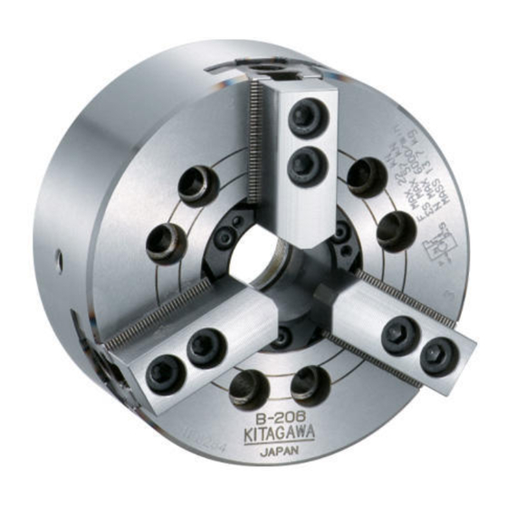
フロン ト中空エアチャ ック
INSTRUCTION MANUAL
取扱説明書
重要
Important
この取扱説明書は製品の操作を担当する生産技術
◇
者および保守担当者を対象にして記載しています。
初心者がご使用される場合は経験者、お買い上げ
販売店、あるいは㈱北川鉄工所の指導を受けて下
さい。
取扱説明書本文にでてくる警告事項の部分は、製
◇
品を使用する前に注意深く読み、内容を充分ご理
解下さい。
この取扱説明書の警告事項に従わなかった場合に
生ずる不具合、事故についての責任は負いかねます。
This manual is prepared for production engineers
◇
and maintenance service men to operate the
products. lf a beginner operates the products, he
should be firstly trained by either a skilled man,
the agent you purchased the products from or
Kitagawa Technical Department prior to the
operation.
Carefully read the warning items in this manual
◇
and understand them thoroughly prior to
the operation. Warranty does not cover any
damage or accident caused without following
the warning items.
将来いつでも使用できるように大切に保管すること。
Please Read and Keep This Manual in a Safe Place.
K,LBtype
Advertisement
Table of Contents

Subscribe to Our Youtube Channel
Related Manuals for Kitagawa UVE L Series


Summary of Contents for Kitagawa UVE L Series
- Page 1 This manual is prepared for production engineers ◇ and maintenance service men to operate the products. lf a beginner operates the products, he should be firstly trained by either a skilled man, the agent you purchased the products from or Kitagawa Technical Department prior to the operation. Carefully read the warning items in this manual ◇ and understand them thoroughly prior to the operation. Warranty does not cover any damage or accident caused without following ...
- Page 2 Keep this manual handy for easy reference as it will 「K I T A G A W A 」 のフロント中空エアチャックをご愛用い help you use many controls to their full advantage. ただき厚くお礼申し上げます。 この取扱説明書によってフロント中空エアチャックの使用 方法を正しくご理解いただき、貴社の生産に寄与できます ようご活用いただければ幸いに存じます。 安全アラート・シンボル SAFETY ALERT SYMBOL This is the industry Safety Alert Symbol. This symbol is これは業界の「安全アラート・シンボル」です。このシンボルは、 used to call your attention to items or operations that could ...
-
Page 3: Table Of Contents
目 次 TABLE OF CONTENTS ……………………… 3 1 .Construction Drawing 1 .構造図 ……………………………………… 3 ……………………… 5 2 .For Safety Operation 2 .ご愛用にあたって、安全のために ………… 5 ……………………………… 11 3 .Specifications 3 .仕様 ………………………………………… 11 …………………… 11 3−1 Specification table 3−1 仕様表 ………………………………… 11 3−2 Relationship between gripping force 3−2 把握力と回転速度の関係 …………… 12 ……………………… 12 and rotary speed 3−3 把握中心高さと静的把握力 3−3 Relationship between gripping center および入力の関係 height and static gripping force トップジョーの質量モーメントと Relationship between top jaw mass 把握力損失の関係 ... - Page 4 1 . 構造図 1 . Construction Drawing UVE160K〜400K構造図 ■ 部品表 Parts list 部 品 名 称 Name of parts Q'ty 部 品 名 称 Name of parts Q'ty A ロックPAD Lock K シリンダカバー Cylinder cover B ボデー Body M シールパッキン Seal packing C フランジ Flange N ダイヤフラムパッキン Diaphragm packing D ピストン Piston P Tナット T−nut E ウエッジプランジャ Wedge plunger Q キャップスクリュー Cap screw F ...
- Page 5 UVE500LB〜800LB構造図 ■ 部品表 Parts list 部 品 名 称 Name of parts Q'ty 部 品 名 称 Name of parts Q'ty A ロックPAD Lock PAD L ダイヤフラムパッキン Diaphragm packing B ボデー Body P Tナット T−nut C フランジ Flange Q キャップスクリュー Cap screw D ピストン Piston T トリツケボルト Mounting bolt E ウエッジプランジャ Wedge plunger V パイロットスプール Pilot spool F スリーブカバー Sleeve cover ...
- Page 6 2 . ご愛用にあたって、安全のために 2 . For Safety Operation Please read this manual and follow instructions ご使用の前に特に知っておいていただきたいこと、守っ carefully. ていただきたいことをまとめてあります。必ずお読み下 We cannot assume responsibility for damage or ac- さい。 cidents caused by misuse of the vise, through non- 尚、この取扱説明書の警告事項に従われなかった場合に compliance with the safety instructions. 生ずる不具合、事故についての責任は負いかねます。 DANGER 危 険 チャックの取付、点検、給油、交換時には、電源を切ること。 SWITCH OFF power before setting, inspecting, lubricating or changing the chuck. 体の一部や衣服が巻き込まれ危険。 There is danger because fingers or clothes may be caught in the chuck.
- Page 7 WARNING 警 告 扉 (ドア) を締めないでスピンドルを起動してはならない。 Don't start spindle with door opened. ドアが閉まってないと回転中のチャックに触れたり、工作物やジョーが飛散することがあり危険。 If door is opened, it may be touched to chuck. Thus, there is danger of scattering workpiece or jaw. 旋盤 LATHE エア圧力は0.6MPa ( 6.1kgf/cm ) を越えてはならない。 Don't exceed 0.6MPa(6.1kgf/cm ) in air pressure. チャックが破損して、チャックや工作物が飛散し危険。 Chuck will be broken and there is danger of scattering chuck or workpiece. 最大エア圧力 Maximum air pressure 0.6MPa (6.1kgf/cm ボルトは規定トルクで締付けること。(P.参照) Tighten bolts with specified torque. (See page ) チャックが破損して、チャックや工作物が飛散し危険。 ボルトサイズ 締付トルク Chuck will be broken and there is danger of scattering Bolt size Tightening Torque c hu c k o r M 5 8.1 N・m ( 0.83 kgf・m) ...
- Page 8 WARNING 警 告 給油は確実に行うこと。(P.参照) Do not forget to grease chuck! (See page ) 給油不足は把握力が低下し工作物が飛散し危険。 Insufficient greasing will reduce chuck gripping force. As a result, there is a danger of scattering workpiece. グリースニップル Grease nipple ルブリケーターのオイル量は適正に保つこと。 Always fill lubricator with oil up to proper level. 給油不足は把握力が低下し工作物が飛散し危険。 Insufficient greasing will reduce chuck gripping force. As a result, there is a danger of scattering workpiece. トップジョーの高さは把握中心高さと静的把握力及びエア圧力の関係のグラフの 範囲以内とすること。(P.〜P.参照) Top jaw height shall be within graphs relative to the gripping center height, static gripping force and air pressure. (See pages and .) チャックが破損して、チャックや工作物が 標準ソフトジョー高さ 特殊トップジョー高さ Standard soft jaw height Special top jaw height 飛散し危険。 Chuck will be broken and there is danger of scattering chuck or workpiece. 標準高さを越える時はエア圧力と回転速度を 落とすこと。 If jaw higher than standard is used, reduce air pressure and spindle speed. 工作物 workpiece...
- Page 9 WARNING 警 告 内径把握は、エア圧力を外径把握の場合の 1 / 2 以下に落とすこと。 When internally gripping work, reduce air pressure by 50% or more in comparison with external gripping of work. チャックが破損して、チャックや工作物が飛散し危険。 Chuck will be broken and there is danger of scattering chuck or workpiece. 1 日 1 回必ずチャック内部の保持エア圧を測定チェックすること。 Be sure to check air pressure once a day. エア圧減少により把握力が低下し工作物が飛散し危険。 Gripping force reduces because of air pressure reduction, thereby resulting 圧力計 in workpiece. scattering. PRESSURE GAGE エア漏れが認められた時は必ず修理すること。 If air leaks, be sure to repair chuck. 突き出しが長い時は振れ止め又はセンタで支持すること。 When machining a long workpiece, support it with a center, tailstock or steady rest. 突き出し長さが長いと工作物が飛散し危険。 If the workpiece is too long, an ejection may occur and causes a severe accident. テールストック Tailstock センタ Center...
- Page 10 WARNING 警 告 安易な改造はしないこと。 Do not attempt to modify chuck. チャックが破損して、チャックや工作物が飛散し危険。 Chuck will be broken and there is danger of scattering chuck or workpiece. こわれる damaged アルコール又は薬物を飲んで操作してはならない。 Never operate machine under influence of alcohol and medicine. 判断力の低下や誤操作により危険。 There is danger due to poor judgment and mis-operation. 薬物 アルコール Drugs Alcohol 手袋、ネクタイ等を着用して操作してはならない。 Gloves and ties should not be worn when operating a machine. 機械に巻き込まれ危険。 There is a danger of being caught into machine.
- Page 11 CAUTION 注 意 チャックを機械に脱着する時は、アイボルト又は吊りベルトを使用する こと。(P.参照) When lifting chuck, use eye bolt or lifting belt. (See page ) 落下により危険。 There is a danger of falling chuck. 吊ベルト アイボルト Lifting Belt Eyebolt 工作物を把握する時、手をはさまれないようにすること。 When gripping workpiece, make sure your hand is out of gripping area. 手指が挫滅や切断し危険。 Danger because fingers may be caught into chuck. チャック、ジョー、工作物へ衝撃を加えないこと。 Never attempt to hammer the chuck, jaws or gripped workpiece. チャックが破損して、チャックや工作物が飛散し危険。 Chuck will be broken and there is danger こわれる! of scattering chuck or workpiece. Damaged 衝撃 SHOCK...
-
Page 12: 3−1 仕様表
3 . 仕様 3 . Specifications 3−1 仕様表 3−1 Specification table UVE160K UVE200K UVE250K UVE315K UVE400K UVE500LB UVE630LB UVE800LB ジ ョ ース トロー ク (直径) mm 8.4 8.4 9.8 9.8 14 17 17 21 Jaw stroke (in dia.) 最大把握径 注 1 )... -
Page 13: 3−2 把握力と回転速度の関係
Since the gripping force is remarkably varied by the weight, shape and mounting position of the top jaw, if きく異なりますから、回転速度が高い場合には、北川把握 the rotary speed is high, it is necessary to measure 力計による実測検討が必要です。 the gripping force with the Kitagawa chuck gripping force tester. WARNING 警 告 In the machining at the high speed, the gripping ... - Page 14 Relationship between rotary speed and gripping force 回転速度と把握力の関係 ○ ○ UVE160K UVE200K (54) (45) 回転速度制限 (3200) Revolution speed limit 1000 2000 (3600) 4000 3000 1000 2000 3000 回転速度:min -1 (rpm) 回転速度:min -1 (rpm) Rotation speed Rotation speed UVE250K UVE315K (111) (90) (2500) 3000 2000 1000...
-
Page 15: 3−3 把握中心高さと静的把握力 および入力の関係 トップジョーの質量モーメントと 把握力損失の関係
3−3 把握中心高さと静的把握力および 3−3 Relationship between gripping center height 入力の関係 and static gripping force トップジョーの質量モーメントと Relationship between top jaw mass moment 把握力損失の関係 and gripping force loss WARNING 警 告 When the top jaw higher than the standard soft jaw 標準ソフトジョーより背の高いトップジョーを使用 ○ ○ is used, or the work is gripped at the top jaw ends, する場合、あるいはトップジョーの先端で把握する reduce the air pressure in inverse proportion to the 場合は、トップジョーの把握中心高さに反比例して gripping center height of the top jaw. If the air pre- エア圧力を下げて使用して下さい。エア圧力を下げ ssure is not reduced, there is the danger of scatte- ないで使用した場合はチャックが破損して、チャッ ring the chuck and work. クや工作物が飛散し危険です。 ○When the large and heavy top jaw is used, the gri- 大きく重いトップジョーを使用する場合、トップジ pping force loss is increased by the centrifugal force ○ of the top jaw, thus resulting in the work scattering. ョー遠心力による把握力損失が大きくなり工作物が In ... - Page 16 トップジョー質量モーメントと把握力損失の関係 把握中心高さと静的把握力及びエア圧力の関係 ○ ○ Relationship between top jaw mass moment and gri- Relationship between gripping center height, static gri- ○ ○ pping force loss pping force and air pressure MM:トップジョーの質量モーメント Jaw Mass Moment UVE160K UVE160K (60) Air pressure エア圧力 (45) Gripping force limit 把握力限界 MM (kg ・ mm) 標準ソフ トジョー (mm) 把握部中心のチャ ック面上高さ Standard soft top jaw mxrx3 Gripping center height...
- Page 17 UVE400K UVE400K (85) (210) 1000 1500 2000 2500 3000 3500 4000 (mm) 把握部中心のチャ ック面上高さ MM (kg ・ mm) 標準ソフ トジョー Gripping center height mxrx3 Standard soft top jaw 標準ソフ トジョー Standard soft top jaw UVE500LB UVE500LB (111) 1000 2000 3000 4000 5000 6000 7000 8000 (mm)...
-
Page 18: 4 .Mounting
4 . 取付 4 . Mounting 4−1 バックプレートの製作・取付 4−1 Manufacturing and mounting of back plate Upon actual measurement of the spindle, the back ○ バックプレートはスピンドルを現物測定の上、嵌合径 ○ plate engagement diameter should be worked. を加工して下さい。 As the run-out accuracy of the back plate will give ○ バックプレートの振れは、直接チャックの精度に影響 ○ influence directly to the chuck accuracy, the run−out しますから、端面の振れ及びインローの振れは、Fig. 3 of back plate and faucet should be less than value に示す値以下にして下さい。 ... - Page 19 WARNING 警 告 Each strength (dia., pieces, material) of mounting バックプレート取付ボルトは十分な強度(径、本数、 ○ ○ bolts for the back plate is to be sufficient. Tighten 材質)を有するものとします。締付けは規定締付ト bolts with specified tightening torque. ルクで締付けて下さい。 If the tightening torque is small or large, there is 締付トルクが不足したり大きすぎるとボルトが破損 the danger of scattering the chuck because bolts し、チャックが飛散し危険です。 are broken. 締付 トルク Tightening Torque ボル トサイ ズ Bolt size 締付 トルク Tightening Torque ボル トサイ ズ Bolt size ...
-
Page 20: 4−2 Locking Air Supply Ring
4−2 エアサプライリングの回り止め 4−2 Locking air supply ring The air supply ring requires the lock. エアサプライリングには回り止めが必要です。 ○ ○ There are two methods to fix the air supply ring and ○ 回り止めには、エアサプライリングを固定しない方法 ○ not to fix it. と固定する方法があります。 When the lock is not fixed, the allowable maximum ○ 固定しない場合は固定する場合と比べて許容最高回転 ○ speed is low in comparison with the case to fix the 速度が低くなります。(P−仕様表参照) ring. (See P− Specification table.) UVE500LB〜UVE800LBは必ず固定が必要です。 ○ Be sure to fix air supply rings for models of UVE500LB ○... - Page 21 IMPORTANT 留意事項 If you don't fix the air supply ring, arrange the air エアサプライリングを固定しない場合、P-⑲の ○ ○ hose horizontally as shown in Fig.4-1 and Fig.4-2 Fig.4-1、Fig.4-2のように、エアホースは水平方向 on page 19. If you arrange the air hose vertically, になるよう配置してください。エアホースが上側や the bearing piece may wear early. It causes 下側から出るように配置すると、ベアリングピース abnormal noise and abnormal heat. が早期に磨耗し、異音や異常発熱の原因となります。 The bearing piece is consumable part. If you use なおベアリングピースは消耗品です。長期間の使用 it for a long term, it is worn. Exchange and repair によっても磨耗しますので、異音や異常発熱がある it if there are abnormal noise and abnormal heat. 場合には交換・修理してください。 (2) When the air supply ring fixed. ( 2 )エアサプライリングを固定する場合 Fix the air supply ring to the lathe with the support. ○ エアサプライ リ ングをサポー トにより旋盤本体と固定します。 ○ Manufacture the support according to dimensions ○...
- Page 22 When using the chucks of UVE500AR〜UVE750AR UVE500AR〜UVE750AR及びUVE500LB〜UVE800LB ○ ○ and UVE500LB〜UVE800LB, though the air supply チャックを使用する場合には、エアサプライリングを ring is fixed onto the chuck with the support, bore サポートで固定しますが、サポートに下図に示すよう the support as shown in the following figure. に穴をあけて下さい。 ・This hole is designed for the purpose of releasing ・この穴はエアサプライリングとチャック本体のスキ the air discharged from the gap between the air マから出るエアを逃がす為の目的で、穴がないと爪 supply ring and the chuck body. When there is no の作動スピードが遅くなります。 hole, the operation speed of jaw becomes delay. ・The hole is to be positioned directly under the su- ・穴の位置は、サポートの真下部かその付近でチャッ...
- Page 23 Fig. 6 UVE500LB〜UVE800LB 型式 Model UVE 5 0 0 LB UVE 6 3 0 LB UVE 8 0 0 LB 項目 Item φ A φ 6 2 0 φ 7 5 5 φ 9 4 0 φ B φ 5 9 8 φ ...
-
Page 24: 4−3 Piping
4−3 配管 4−3 Piping Route pipes of chuck, change valve and air unit as チ ャ ッ ク・切換弁・エアユニ ッ トをFig. 7の様に配管します。 ○ ○ shown in Fig. 7. 切換弁は、必ず 3 位置 4 方向エキゾーストセンタ形を ○ Be sure to use exhaust center type pipe of 3−position ○ 使用して下さい。 and 4−direction. チャックへの配管接続口径はFig. 7表に示すサイズです。 ○ The piping connection bore is according to sizes as ○... -
Page 25: 4−4 Electric Circuit Diagram For Reference
4−4 参考電気回路図 4−4 Electric circuit diagram for reference The sequence circuit using the pressure switch of 押しボタン式で圧力スイッチを使用した例のシーケン ○ ○ push button is shown in Fig. 9. ス回路をFig. 9に示します。 Use this diagram for reference. ○ 本図は参考図として御使用下さい。 ○ Prepare the diagram so that the chuck does not ○ 主軸回転中には、チャックが絶対作動しない回路にす ○ operate during spindle rotation. ることが必要です。 Since the spindle, chuck, work, etc., are immedia- ○... -
Page 26: 5 .Adjustment Of Gripping Check Switch
5 . 把握確認スイッチの調整 5 . Adjustment of Gripping Check Switch Since models of UVE500LB〜800LB are equipped UVE500LB〜800LBには近接スイッチが内蔵されてお ○ ○ with proximity switches, then can be used for work り、ワークの把握確認に利用できます。このスイッチ gripping check. Consequently, design the high safe- のON、OFF信号を主軸回転のインターロック回路や ty circuit diagram by using ON/OFF signals of swi- ワーク搬送機の搬出指令等に用い、安全度の高い回路 tch to the interlock circuit of spindle speed, work tra- 設計を行って下さい。 nsfer command, etc. ワークの把握時、非把握時を正しく検出する為に、近 ○ To correctly detect the work clamp and unclamp, it ○... -
Page 27: 6 .Trial Run
6 . 試運転 6 . Trial Run When completing the mounting and piping of a chuck, チャックの取付・配管が完了したら、以下の手順で試 ○ ○ perform a trial run according to the following procedure. 運転を行って下さい。 ①Ensure the master jaw is greased. ①マスタジョーへのグリースアップを行って下さい。 ②Fill with recommended oil (ISO VG32) up to upper ②エアユニットのルブリケーター上部の給油口より、推 limit of indicator line from oil supply port located on 奨使用油(ISO、VG32)を上限まで給油して下さい。 upper control unit. (Be careful not to enter dust (ゴミが混入しない様留意下さい) when oil is supplied.) ③エア圧力調整ハンドルを回して圧力を徐々に上昇させ ③Raise pressure gradually by turning the air pressure adjusting handle. With the pressure gauge pointed 2 ます。圧力計の指針が 2 〜2.5kgf/cm になったところ to ... -
Page 28: 7 .Mounting Of Top Jaw
7 . トップジョーの取付 7 . Mounting of Top Jaw Mount the top jaw with T-nut and mounting bolt to トップジョーはTナットと取付ボルトによりマスタ ○ ○ the master jaw. The engaged position of the serra- ジョーに取付けます。トップジョーの位置は、マスタ tionengaged position for the master jaw can be free- ジョーとのセレーションかみ合い位置を変えることに ly adjusted. より自由に調整出来ます。 WARNING 警 告 Use T−nut at the place where it is not protruded Tナットは、マスタジョーのセレーション基準位置(セ... - Page 29 WARNING 警 告 If the screwing depth is shallow for トップジョー取付ボルトのTナットに対 ○ ○ T−nut of the top jaw mounting bolt, するネジ込み深さが浅いと、Tナットが T−nut may be broken and there is 破損し、ジョーや工作物が飛散し危険 the danger of scattering the jaw and です。又、Tナット底面から突出してい work. If protruded from T−nut bott- ると取付ボルトを締付けてもトップジ om, the top jaw is not fixed even if ョーが固定されないでジョーや工作物...
-
Page 30: 8 .Forming Of Soft Jaws
8 . ソフトジョーの成形 8 . Forming of soft jaws Perform forming of the soft jaw according to the ○ ソフトジョーの成形は下表の要領で行って下さい。 ○ procedure of the following table. IMPORTANT 留意事項 外径把握の場合 External gripping 内径把握の場合 Internal gripping 成形用プラグ を用意します。 成形用リ ング を用意します。 ● ● プラグの外径は▽▽▽仕上げ程度と し、 歪 リ ングの内径は▽▽▽仕上げ程度と し、 歪 まない厚さのある ものを使用下さい。 まない厚さのある... - Page 31 プラグを把握したままの状態で工作物把 リ ング を把握したま まの状態で工作物把握 ● ● 握部 (φd') を成形します。 部 (φd') を成形します。 φ d'部は工作物の把握部直径と同径 (H 7 ) φd'部は工作物の把握部直径と同径 (h 7 ) 程度に、 表面アラサは 6S以下に加工して 程度に、 表面アラサは 6S以下に加工して 下さい。 下さい。 成形時の圧力は、 工作物加工時と同圧又 成形時の圧力は、...
- Page 32 IMPORTANT 留意事項 Method for forming in case higher chucking accuracy is 高把握精度が必要な場合の成形方法 required (e. x., O. D. chucking) (例:外径把握) (1) When forming jigs as shown in Fig. are used, soft 図の様な成形用治具を使用すれば、工作物を加工する jaw will be formed under conditions same as for those 時と同様な状態でソフトジョーを成形することになり during machining of work (the fulcrum of the soft jaw (工作物を把握した時のソフトジョーの力の支点が上 force during work chucked is positioned above) mak- となる)、高把握精度を得ることができます。 ing it possible to obtain high chucking accuracy. 成形用治具 を用意 し ま す。 (市販品も あ り ま す。 ) Make ...
-
Page 33: 9 .Usage Of Collet Pad
9 . コレットパット使用について 9 . Usage of collet pad UVE500LB〜800LB can be equipped with the collet UVE500LB〜800LBにはコレットパットが装着できます。 ○ ○ pad. マスタジョー中心側にタップ穴( 2 ヶ所)及びボルト ○ The tapping hole (2 positions) and the bolt stop ○ ザグリ穴を設けてありますので長尺バー、パイプ等の facing hole (1 position) are provided on the center 外径把握に御利用下さい。 side of the master jaw to grip longer length work pieces on the outside diameter. - Page 34 ○ アンバランスの大きい工作物の場合、工作物の偏心 ○ with low speed since the centrifugal force by work 質量による遠心力がジョーにかかるので十分検討し eccentric mass is applied to the jaw. 低い回転速度で加工して下さい。 If the top jaw except Kitagawa brand is used, the ○ 北川鉄工所以外のトップジョーを使用すると嵌合状態 engaged status is improper and the master jaw may ○ be distorted, thus causing the danger of scattering が悪くマスタジョーが変形して把握精度不良や把握力 the work due to gripping accuracy failure and insu- 不足により工作物が飛散し危険です。(類似品に注意) ...
- Page 35 WARNING 警 告 There is a possibility that master jaw is damaged if 異形の把握をしますとマスタジョーが破損する可能 ○ ○ strangely shaped workpiece will be clamped. If 性がありますので、ご相談下さい。 required, please contact our Service Engineering Dept. 斜線部追加工可能範囲 Fig. 14 Additionally Machinable Range on Oblique Line Part 項目 Item A B C D E F G H 型式 Model 18以下 UVE160K 62 − 58 40.5 ...
-
Page 36: 11.Maintenance And Inspection
って、潤滑給油は確実に行って下さい。 of gripping force. 給油ヶ所 使用オイル 給油回数・時期 Place Cycle Once a day. 各マスタジョー 毎日 1 回 Grease to 「Kitagawa chuck grease」 「キタガワ チャ ッ ク グリース」 Apply the grease of about 5g to グリス量の目安として、各マ (北川純正 : 各国北川代理店) (Kitagawa standard grease is 外周部のグリー grease nipple the each master jaw to size 8 スタジョー毎に 8 インチサイ... - Page 37 外周および端面振れが小さくなる様に調整し、ボルトを締付 回転軸とチャック芯が合っていない。 ける。 マスタジョー、トップジョーのセレー トップジョーを取外した後、 セレーション部をよく清掃する。 ション部にゴミが付着している。 トップジョーの取付ボルトが十分締ま トップジョーの取付ボルトを規定トルクで締付ける。但し、 っていない。 締め過ぎに注意。 成形プラグがチャック端面に対して平行かどうか、成形プラ ソフトジョーの成形方法が不適当であ グが把握力のために変形していないかを確かめる。また、成 る。 形時の油圧力、成形部の面粗度などをチェックする。 トップジョーの高さが高過ぎ、トップ トップジョーの高さを低くする。 (標準サイズと取換える。 ) ジョーが変形したり、トップジョー取 把握当り面をチェックし均等にする。 付ボルトが伸びている。 把握力が強過ぎ、工作物を変形させて 加工できる範囲で、把握力を低くして変形を防止する。 いる。 故障の修理は KITAGAWAの販売店又は、KITAGAWAの支店へお申しつけ下さい。 簡単なものはその場で修理致します。長くかかるものは予定をお知らせします。 ○ お持ちこみが困難な場合は、電話で御連絡下さい。 ○ 連絡先は購入頂いた販売店又は裏表紙の弊社支店までお申しつけ下さい。 ○...
- Page 38 12. Troubleshooting If trouble occurs ; Stop the lathe, and try the following counter measures. ○ Trouble Cause Countermeasures Chuck will Chuck parts broken. Disassemble and replace part. not operate Check that pressure reducing valve, change over valve and Slideway seizes. hose system are correct. Check that pressure reducing valve, change over valve and Compressed air is inadequate. hose system are proper. Friction of bearing piece, damage of air supply ring and cylinder Replace it after disassembling. O-ring. Inadequate function of lock PAD. Disassemble and clear the lock PAD. Insufficient Too much swarf in chuck. Disassemble and clean. master jaw Rust occurs at slide part. ...
-
Page 39: Parts List Of Front−End Open Center Air Chuck
13. UVE160K〜400K 13. UVE160K〜400K フロント中空エアチャックパーツリスト Parts list of front−end open center air chuck... - Page 40 品 名 チ ャ ッ ク型式 部品番号又は規格 個 数 Description Type Part No. & Standard Q'ty A ロ ッ クPAD UVE160K 1 Lock PAD ロ ッ クPAD パーツ リ ス ト ...
- Page 41 品 名 チ ャ ッ ク型式 部品番号又は規格 個 数 Description Type Part No. & Standard Q'ty M シールパッ キン UVE160K 61P−40−1338 2 Seal packing UVE200K 61P−40−1338 UVE250K 61P−40−1338 ...
- Page 42 品 名 チ ャ ッ ク型式 部品番号又は規格 個 数 Description Type Part No. & Standard Q'ty 05 六角穴付ボタ ンネジ UVE160K M5×12 6 Hexagon socket head cap UVE200K M5×12 screw UVE250K M5×12 ...
- Page 43 品 名 チ ャ ッ ク型式 部品番号又は規格 個 数 Description Type Part No. & Standard Q'ty 16 軸用ゼーガ リ ング A型 UVE160K A56 1 UVE200K A75 UVE250K A85 ...
-
Page 44: Designations Of Components Of Front−End
14. UVE500LB〜800LB 14. UVE500LB〜800LB フロント中空エアチャックパーツリスト Designations of components of front- end open center air chuck UVE…L,LB分解図 Assembly drawing of UVE…L, LB ... - Page 45 品 名 チ ャ ッ ク型式 部品番号又は規格 個 数 Description Type Part No. & Standard Q'ty ロ ッ クPAD パーツ リ ス ト A ロ ッ クPAD UVE 5 0 0 LB 1...
- Page 46 品 名 チ ャ ッ ク型式 部品番号又は規格 個 数 Description Type Part No. & Standard Q'ty V パイ ロ ッ トスプール UVE 5 0 0 LB 6 1 P− 4 0 − 5 2 9 8 3...
- Page 47 品 名 チ ャ ッ ク型式 部品番号又は規格 個 数 Description Type Part No. & Standard Q'ty 0 8 六角穴付ボル ト UVE 5 0 0 LB M 1 6 × 3 5 6...
- Page 48 品 名 チ ャ ッ ク型式 部品番号又は規格 個 数 Description Type Part No. & Standard Q'ty 2 8 コネ クタ UVE 5 0 0 LB MS 3 1 0 2 A1 6 S− 8 P 1...
-
Page 49: 15.Designations Of Lock Pad Components
15. ロックPADパーツリスト 15. Designations of lock pad components The lock PAD is the core part of the front−end thru- ロックPAD、フロント中空エアチャックの心臓部であ ○ ○ hole air chuck. Please handle with care. り、取扱いには、十分注意して下さい。 Please take care not to mark a ball or a valve sheet. ○ ボール、バルブ シー トに傷を付けないように注意して下さい。 ○ The mark would cause the reduction of chucking 傷が入ると把握力の減少、ワー クの飛散等の原因になり force and the discharge of a work piece, etc. ます。 When removing or assembling, please take care not ○ 取外し、組立時にOリングが破損しないように注意し ○ to damage O−rings. て下さい。(Oリングにマシン油を塗布して下さい) When removing, please take care not to lose a coil ○... - Page 50 MEMO...
Need help?
Do you have a question about the UVE L Series and is the answer not in the manual?
Questions and answers