Emerson Rosemount 975 Series Reference Manual
Flame detectors
Hide thumbs
Also See for Rosemount 975 Series:
- Reference manual (36 pages) ,
- Quick start manual (20 pages) ,
- Quick start manual (28 pages)

Related Manuals for Emerson Rosemount 975 Series


Summary of Contents for Emerson Rosemount 975 Series
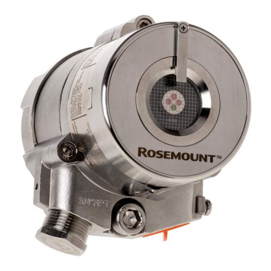
- Page 1 Reference Manual 00809-1400-4975, Rev AB February 2022 ™ Rosemount Flame Detectors...
- Page 2 Emerson does not assume any liability arising out of the application or any use of any product or circuit described herein;...
- Page 3 Only access the wiring compartment to wire or remove the detector or access RS-485 terminals for maintenance. Technical support To get technical support for this product, contact your local Emerson representative or the Emerson Technical Support department at +1 866 347 3427 or safety.csc@emerson.com.
- Page 4 Abbreviation or acronym Definition Not applicable NFPA National Fire Protection Association National pipe thread RS485 Communication protocol allowing bi-directional communication Part number Safety integrity level Unified coarse thread Volts alternating current Volts direct current...
-
Page 5: Table Of Contents
Reference Manual Contents 00809-1400-4975 February 2022 Contents Chapter 1 Introduction......................7 1.1 Product overview.........................7 1.2 Models............................7 Chapter 2 Installation.........................9 2.1 Installation guidelines........................9 2.2 Preparation for use........................9 2.3 Attach detector to tilt mount.....................13 2.4 Open the back cover........................14 2.5 Wire terminals and ground cable.................... - Page 6 Contents Reference Manual February 2022 00809-1400-4975 A.2 Product certifications and installation drawings.................37 Appendix B FM fuel test responses ..................... 39 Appendix C Immunity to false alarm sources................41 Emerson.com/Rosemount...
-
Page 7: Chapter 1 Introduction
February 2022 Introduction Product overview The Rosemount 975 series is based on proven technologies, including triple infrared (IR3) and ultraviolet infrared (UV/IR). The Rosemount 975 series provides the fastest response to fire, longest distance detection, and revolutionary UV/IR technology, coupled with superior immunity to false alarms, functioning in harsh conditions with unparalleled reliability and durability. - Page 8 Do not attempt to modify or repair the internal circuits or change their settings, as this will impair the system's performance and void the Emerson product warranty. NOTICE Opening the attachment screws to dismantle the front part of the detector form the remaining parts is restricted and voids the product warranty.
-
Page 9: Chapter 2 Installation
Reference Manual Installation 00809-1400-4975 February 2022 Installation Installation guidelines Installation should comply with the National Fire Protection Association (NFPA) 72E or any other local and international regulations and standards, as applicable to flame detectors and installation of Ex approved products. To ensure optimal performance and efficient installation, consider the following guidelines. - Page 10 Flat screwdriver 2.5 mm Connect wires to the terminal blocks. Hex key ⅜-in Stop plug ¾-in NPT. Open wrench 28 mm Stop plug M25 only. 2.2.1 Field of view Figure 2-1: Horizontal field of view for Rosemount 975MR, 975UF, and 975UR Emerson.com/Rosemount...
- Page 11 Reference Manual Installation 00809-1400-4975 February 2022 Figure 2-2: Vertical field of view for Rosemount 975MR, 975UF, and 975UR • +50 ° (down) • -45 ° (up) Gasoline For Rosemount 975HR. • Horizontal: 80 ° • Vertical: 80 ° Rosemount 975...
- Page 12 Installation Reference Manual February 2022 00809-1400-4975 Figure 2-3: Vertical and horizontal field of view for gasoline Hydrogen For Rosemount 975HR. • Horizontal: 90° • Vertical: 90° Figure 2-4: Horizontal field of view for hydrogen Emerson.com/Rosemount...
-
Page 13: Attach Detector To Tilt Mount
Reference Manual Installation 00809-1400-4975 February 2022 Figure 2-5: Vertical field of view for hydrogen Attach detector to tilt mount Procedure 1. Unpack the detector. 2. Insert location pins on the tilt mount into the openings on detector housing. 3. Thread the holding screw and tighten it. Rosemount 975... -
Page 14: Open The
Do not open the housing while the power is on. Procedure 1. Loosen the back cover security screw. A. Back cover security screw B. Protective plug 2. Unscrew the back cover. Note The back cover is attached by a security cable. 3. Remove the protective plug. Emerson.com/Rosemount... -
Page 15: Wire Terminals And Ground Cable
Reference Manual Installation 00809-1400-4975 February 2022 Wire terminals and ground cable CAUTION Improper wiring may damage the detector. Procedure 1. Connect the terminals according to Table 2-2. The terminal details are also on the inside back cover. Figure 2-6: Terminal box Rosemount 975... - Page 16 0-20 mA (+) 0-20 mA (-) Alarm output RS485 (+) RS485 (-) Accessory relay - normally open Accessory relay Accessory relay - normally closed 2. Use Figure 2-7, Figure 2-8, Figure 2-9, and Figure 2-10 for typical wiring configurations. Emerson.com/Rosemount...
- Page 17 Reference Manual Installation 00809-1400-4975 February 2022 Figure 2-7: Typical wiring for four-wire controllers A. Controller B. First detector C. Second detector D. Last detector E. Power supply F. Alarm loop G. End of line Figure 2-8: Non-isolated sink (three wires) A.
- Page 18 For additional configuration options, please refer to the Rosemount 975 Flame ® Detectors Modbus Manager Manual. 3. Check the wires for secure mechanical connection and press them neatly against the terminal to prevent them from interfering while closing the back cover. Emerson.com/Rosemount...
-
Page 19: Install The Protective Cover
Reference Manual Installation 00809-1400-4975 February 2022 4. Close the terminal compartment by screwing the back cover on to the housing. 5. Tighten the back cover security screw. Figure 2-11: Closing security screw A. Back cover security screw B. Ground cable connection point 6. -
Page 20: Aim The Detector
Aim the detector toward the center of the detection zone and make sure you have a completely unobstructed view of the protected area. Emerson recommends positioning the detector tilted down at a 45° angle to maximize coverage and prevent accumulation of dust and dirt. -
Page 21: Changing Default Detector Settings
Reference Manual Installation 00809-1400-4975 February 2022 Changing default detector settings ® ® The Main settings that can be modified using the Modbus Manager or HART communication include: • Built-in test (BIT) • Detection options • Lock option • 4-20 mA settings •... - Page 22 Installation Reference Manual February 2022 00809-1400-4975 Emerson.com/Rosemount...
-
Page 23: Chapter 3 Operation
Reference Manual Operation 00809-1400-4975 February 2022 Operation Power up the detector Procedure After connecting the detector to power, wait up to 60 seconds for the detector to completed the initial start-up procedure. Note Turning on the detector initiates the following sequence of events: a. - Page 24 Operation Reference Manual February 2022 00809-1400-4975 Table 3-2: Flame simulator Reference Manuals Rosemount flame simulator Reference Manual FS-HR-975 00809-0900-4975 FS-IR-975 00809-0500-4975 FS-UVIR-4975 00809-0800-4975 Related information Power up the detector Emerson.com/Rosemount...
-
Page 25: Chapter 4 Initial Setup
Reference Manual Initial setup 00809-1400-4975 February 2022 Initial setup Continuous feature test The detector is supplied with default settings, including a continuous feature test. ® To change these settings, refer to the Rosemount 975 Flame Detectors Modbus Manager Manual. During normal operation, the detector tests itself continuously and indicates a fault if a failure is found. - Page 26 Manual BIT You can initiate manual BIT using the Modbus Manager or HART communicator or by connecting terminal 3 to ground. You can also use the Modbus Manager or HART communicator to configure the manual BIT's alarm duration. Emerson.com/Rosemount...
-
Page 27: Chapter 5 Maintenance
Reference Manual Maintenance 00809-1400-4975 February 2022 Maintenance Keeping maintenance records Record all maintenance operations performed on a detector in accordance with site guidance and requirements. Clean the detector Procedure 1. Disconnect power from the flame detector. 2. Wipe the detector housing with clean water and a damp cloth. NOTICE Do not use a brush or sharp tools to clean the device. - Page 28 Maintenance Reference Manual February 2022 00809-1400-4975 Emerson.com/Rosemount...
-
Page 29: Chapter 6 Troubleshooting
Reference Manual Troubleshooting 00809-1400-4975 February 2022 Troubleshooting Light-emitting diode (LED) is off, fault relay is open, 0-20 mA shows 0 mA, analog voltage output is 0 V Potential cause No power to the unit. Recommended actions 1. Check that the operating voltage is correct, according to Electrical specifications. -
Page 30: Light-Emitting Diode (Led) Constantly Red, Alarm Relay Energized, 0-20 Ma Indicates Alarm
No HART is available at 0 mA level. Recommended action For Fault mode, the default indication is 1 mA. Configure this to 0 mA. Emerson does not recommend this when using a HART connection in order to preserve the HART communication. Emerson.com/Rosemount... -
Page 31: Chapter 7 Specifications
Reference Manual Specifications 00809-1400-4975 February 2022 Specifications Technical specifications Spectral response Rosemount 975MR Four infrared (IR) bands between 4 μm and 5 μm Rosemount 975HR Four IR bands between 2 μm and 5 μm Rosemount 975UF Ultraviolet (UV): 0.185 - 0.260 μm IR: 2.5-3.0 μm Rosemount 975UR UV: 0.185 - 0.260 μm... - Page 32 207 ft (63 m) 70 ft (21 m) Battery 279 ft (85 m) 75 ft (23 m) Contact Emerson representative for guidance on detecting magnesium alloy. One battery cell. Standard response time Table 7-2: Rosemount 975 Models Rosemount 975MR Rosemount 975HR...
-
Page 33: Electrical Specifications
Reference Manual Specifications 00809-1400-4975 February 2022 Sensitivity ranges Note All distances relate to detection of a 1 ft (0.1 m ) n-heptane fire. Table 7-5: Rosemount 975 Models Rosemount 975MR Rosemount 975HR Rosemount 975UF Rosemount 975UR Six ranges: Three ranges: •... -
Page 34: Mechanical Specifications
(35 °C). The detector stops heating the window when the temperature is 15 °C above the start temperature. Mechanical specifications Enclosure options Stainless steel 316 with electropolish finish Heavy duty copper free aluminum (less than one percent), polyurethane painted Rosemount 975 flame detectors also have a low power heater option. Emerson.com/Rosemount... - Page 35 Reference Manual Specifications 00809-1400-4975 February 2022 Tilt mount Stainless steel 316 with electropolish finish Detector dimensions 4 in (100.6 mm) x 4.6 in (117 mm) x 6.18 in (155 mm) Weight Stainless steel detector: 6.3 lb (2.9 kg) Aluminum detector: 2.8 lb (1.3 kg) Tilt mount 2.5 lb (1.13 kg) Environmental standards DNV 2-4...
- Page 36 Specifications Reference Manual February 2022 00809-1400-4975 Emerson.com/Rosemount...
-
Page 37: Appendix A Reference Data
4. Select DATA SHEETS & BULLETINS. 5. Select the appropriate Product Data Sheet. Product certifications and installation drawings To view current Rosemount 975 Series product certifications and installation drawings, follow these steps: Procedure 1. Go to Emerson.com/en-us/catalog/flame-detectors. 2. Select the appropriate product. - Page 38 Reference data Reference Manual February 2022 00809-1400-4975 Emerson.com/Rosemount...
- Page 39 Reference Manual FM fuel test responses 00809-1400-4975 February 2022 FM fuel test responses Results of the FM fuel tests are as follows: Table B-1: Rosemount 975 Models Fuel Rosemount Rosemount Rosemount Rosemount 975MR 975HR 975UF 975UR Gasoline 295 ft (90 m) 92 ft (28 m) N-Heptane 295 ft (90 m)
- Page 40 76 ft (23 m) 1 ft (0.1 m ) pan fire Plume fire: 2.5 ft (0.75 m) high, 0.8 ft (0.25 m) wide Only for ultraviolet (UV) detector 1.5 in (10 cm ) pan fire Ten pieces per test One battery cell Emerson.com/Rosemount...
- Page 41 Reference Manual Immunity to false alarm sources 00809-1400-4975 February 2022 Immunity to false alarm sources Table C-1: Immunity to false alarm sources IAD: Immunity at any distance Radiation source Immunity distance Rosemount Rosemount Rosemount Rosemount 975MR 975HR 975UF 975UR Indirect or reflected sunlight Vehicle headlights (low beam) conforming to MS53023 Incandescent frosted glass light, 300 W...
- Page 42 50 ft (15 m) >43 ft (13 m) >50 ft (15 m) >15 ft (4.5 m) >16 ft (5 m) 93 ft (28 m) >66 ft (20 m) >70 ft (21 m) >27 ft (8 m) >30 ft (9 m) Emerson.com/Rosemount...
- Page 43 Reference Manual 00809-1400-4975 February 2022 Rosemount 975...
- Page 44 2022 Emerson. All rights reserved. Emerson Terms and Conditions of Sale are available upon request. The Emerson logo is a trademark and service mark of Emerson Electric Co. Rosemount is a mark of one of the Emerson family of companies. All other marks are the property...
Need help?
Do you have a question about the Rosemount 975 Series and is the answer not in the manual?
Questions and answers