
Subscribe to Our Youtube Channel
Related Manuals for R.V.R. Elettronica PJ2500M-C


Summary of Contents for R.V.R. Elettronica PJ2500M-C
- Page 1 PJ2500M-C, PJ3000HE, PJ3500M-C, PJ4000U-K, & PJ5000U-K User manual Volume 1 Manufactured by Italy...
- Page 2 Date Version Reason Editor 29/06/2009 First Version J. H. Berti PJ2500M-C, PJ3000HE, PJ2500M-C, PJ4000U-K & PJ5000U-K - User Manual Version 1.0 © Copyright 2009 R.V.R. Elettronica SpA Via del Fonditore 2/2c - 40138 - Bologna (Italia) Telefono: +39 051 6010506...
-
Page 3: Table Of Contents
PJ2500M-C, PJ3000HE, PJ3500M-C, PJ4000U-K & PJ5000U-K Table of Contents Preliminary Instructions Warranty First Aid Treatment of electrical shocks Treatment of electrical Burns General Description Make-up Quick installation and operating reference Preparation Operation Software Protection System External Description PS Module Frontal Panel... - Page 4 PJ2500M-C, PJ3000HE, PJ3500M-C, PJ4000U-K & PJ5000U-K This page was intentionally left blank Rev. 1.0 - 29/06/09 User Manual...
-
Page 5: Preliminary Instructions
If it is decided to return the that the manufacturer’s instructions are been followed. unit to the factory, R.V.R. Elettronica will mail you a regular authorization with all the necessary instructions to send back the goods;... -
Page 6: First Aid
PJ2500M-C, PJ3000HE, PJ3500M-C, PJ4000U-K & PJ5000U-K R.V.R. is never responsible for damage or loss), until the package reaches R.V.R. premises. For this reason, we suggest you to insure the goods for the whole value. Shipment must be effected C.I.F. (PREPAID) to the address specified by R.V.R.’s service manager on the... -
Page 7: General Description
4000W, for the PJ3500M-C the max. rated output is 3500W, for the PJ3000HE the max. rated output is 3000W while for the PJ2500M-C model the max. rated output is of 2500 watts. They are a fully solid-state apparatus of modern design that use MOSFET as active components in the FM amplifying modules. - Page 8 PJ2500M-C, PJ3000HE, PJ3500M-C, PJ4000U-K & PJ5000U-K • Activating and deactivating power delivery • Protecting the amplifier as far as potentially harmful situations are concerned such as excess supplied power, SWR, excessive pilot power or temperature • Detecting the warning thresholds set by the user (e.g. power delivered below...
-
Page 9: Quick Installation And Operating Reference
PJ2500M-C, PJ3000HE, PJ3500M-C, PJ4000U-K & PJ5000U-K 5. Quick installation and operating reference The scope of this chapter is to summarize the procedures for installing the machine. If any point is not fully comprehensible, such as how to operate the machine the first time, it is advisable to read the entire manual very carefully. - Page 10 PJ2500M-C, PJ3000HE, PJ3500M-C, PJ4000U-K & PJ5000U-K • Data connection by means of cable with DB37 connectors (PS-RF Interconnection) • Ground connection between each module chassis • Power supply connection by means of cable coming out of the PS module ending with the ILME CXM 4/2 type of socket (DC Output).
- Page 11 PJ2500M-C, PJ3000HE, PJ3500M-C, PJ4000U-K & PJ5000U-K Figure 5-1 Example of PJ4000/5000U-K installation in a rack Connect the output of a suitable type of FM exciter (e.g. the PTXLCD of R.V.R. Elettronica) to the RF input (RF module) using a cable fitted with N type connectors.
-
Page 12: Operation
PJ2500M-C, PJ3000HE, PJ3500M-C, PJ4000U-K & PJ5000U-K Figure 5-2: View of the mains multipole socket - terminals side (internal) Single-phase power supply: • G Ground • 1 Neutral • 2 Phase • 3 Not connected • 4 Not connected • 11,12 Not connected Danger: avoid the risk of damaging the machine by grounding it correctly. -
Page 13: Software
PJ2500M-C, PJ3000HE, PJ3500M-C, PJ4000U-K & PJ5000U-K 2500 watts for PJ2500M-C model (keep in mind that due to the measurement digitalization effect it might not be possible to obtain a reading of exactly 5 kW, 4 kW, 3.5 kW, 3 kW o 2.5kW, but a lightly higher or lower value which is perfectly normal). - Page 14 PJ2500M-C, PJ3000HE, PJ3500M-C, PJ4000U-K & PJ5000U-K Switch On Selection Menu ENTER Operation Menu ENTER Power Menu ENTER P.A. Menu ENTER Set Up Menu ENTER Alarm Menu ENTER Miscellaneous Menu ENTER Version Menu Figura: Flow diagram of the software When turned on, the LCD shows the introductory screenful with the equipment’s software and hardware versions.
- Page 15 PJ2500M-C, PJ3000HE, PJ3500M-C, PJ4000U-K & PJ5000U-K To access one of the submenus select its name (which is underlined by a blinking cursor) using the RIGHT or LEFT keys and then press the ENTER key. Take note that certain parameters, which are measured and shown to the user, might not be available in a few cases.
- Page 16 PJ2500M-C, PJ3000HE, PJ3500M-C, PJ4000U-K & PJ5000U-K The figure below shows the complete aspect of this screen (only two lines can be seen at a time, use the UP and DOWN keys to scroll through it): 5.3.3 Power Amplifier Menu (P.A.)
- Page 17 2800 W (80% x 3500 W x mod. PJ3500M-C) 2400 W (80% x 3000 W x mod. PJ3000HE) 2000 W (80% x 2500 W x mod. PJ2500M-C) • PwtGd2 2500 W (50% x 5000 W x mod. PJ5000U-K) 2000 W (50% x 4000 W x mod.
- Page 18 PJ2500M-C, PJ3000HE, PJ3500M-C, PJ4000U-K & PJ5000U-K It consists of a certain number of lines each of which contains the name of the variable controlled by the protection system and the type of intervention carried out by the system. Said intervention may be as follows: X - (Y), Wait, or Dis. (Disabled).
-
Page 19: Protection System
PJ2500M-C, PJ3000HE, PJ3500M-C, PJ4000U-K & PJ5000U-K In the analog display mode a small triangle indicates the reflected power level set in the Alarm Threshold Setting Menu (RflWar), whereas the bar at the bottom shows the instant reflected power level. This type of display might be useful when a device to be tuned is connected to the amplifier’s output such as a cavity. - Page 20 PJ2500M-C, PJ3000HE, PJ3500M-C, PJ4000U-K & PJ5000U-K • If the equipment is off, waiting for the cycle time to be reached, or if it is definitively off in FAULT state, press the ALARMS RESET button to immediately turn the amplifier ON and reset the alarm counters.
-
Page 21: External Description
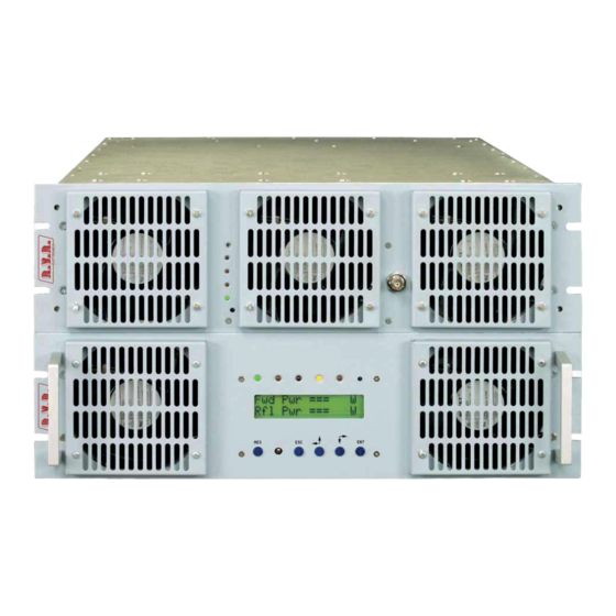
PJ2500M-C, PJ3000HE, PJ3500M-C, PJ4000U-K & PJ5000U-K 6 External Description This chapter describes the elements presents on the panels of the PJ2500M-C, PJ3000HE, PJ3500M-C, PJ4000U-K and PJ5000U-K. 6.1 PS Module Frontal Panel [1] AIR FLOW Grill for the ventilation flow passage... -
Page 22: Ps Module Rear Panel
PJ2500M-C, PJ3000HE, PJ3500M-C, PJ4000U-K & PJ5000U-K 6.2 PS module Rear Panel [1] MAINS FUSE Protection fuses of the power supplies 1,2 and 3 [2] MAINS CONNECTOR Plug for mains power supply [3] AIR FLOW Grill for the ventilation flow passage... -
Page 23: Connector Description
PJ2500M-C, PJ3000HE, PJ3500M-C, PJ4000U-K & PJ5000U-K 6.3 Connector Description 6.3.1 Telemetry Connector Type: DB25 Female Internal SWR 3,9V x 1/2W Tensione dell’ amplificatore di potenza RF 3,9V x 50V Reflected Power 4.3V x 200W Interlock Set 4 “On” Command Set 1... - Page 24 PJ2500M-C, PJ3000HE, PJ3500M-C, PJ4000U-K & PJ5000U-K 6.3.3 I C Connector Type: DB9 Female Serial Data Serial Clock 6.3.4 Com Bus Type: DB15 male 485+ 485- ON OFF C INP PWR ST BY PWR REG 20 / 38 Rev. 1.0 - 29/06/09...
- Page 25 PJ2500M-C, PJ3000HE, PJ3500M-C, PJ4000U-K & PJ5000U-K 6.3.5 Interconnection PS-RF Type: DB37 female GND, Internally connected with 12/14/15/23/25/26/28/31/33 V TOT R PWR TEMP PS OFF PS REG PWR REG ON OFF CLIX RESET AL GND, Internally connected with 1/14/15/23/25/26/28/31/33 485+ GND, Internally connected with 1/12/15/23/25/26/28/31/33...
-
Page 26: Rf Module Frontal Panel
PJ2500M-C, PJ3000HE, PJ3500M-C, PJ4000U-K & PJ5000U-K 6.4 RF Module Frontal Panel [1] AIR FLOW Grill for the ventilation flow passage [2] FAULT Red LED that indicates a fault that cannot be automatically reverted [3] FUSE BLOWN Red LED that indicates the presence of one or more broken... -
Page 27: Rf Module Rear Panel
PJ2500M-C, PJ3000HE, PJ3500M-C, PJ4000U-K & PJ5000U-K 6.5 RF module Rear Panel [1] RF OUT RF output connector (7/8” EIA flange) [2] PLUG 1 Plug 1 for the supply of 50V incoming from module PS [3] PLUG 2 Plug 2 for the supply of 50V... - Page 28 AC3, internally connected with 17 GND, Internally connected with PIN34 of JP5 of the Bias board SLMTPRTPJ4K1(mod. PJ3500M-C, PJ4000U-K & PJ5000U-K). NC (mod. PJ3000HE & PJ2500M-C) AC4, internally connected with Internamente connesso con 19 24 / 38 Rev. 1.0 - 29/06/09...
-
Page 29: Technical Specification
PJ2500M-C, PJ3000HE, PJ3500M-C, PJ4000U-K & PJ5000U-K 7. Technical Specification PJ2500M-C PJ3000HE PJ3500M-C Parameters GENERALS Rated output power 2500W 3000W 3500W FCC -CCIR and other on request Frequency range Input power for rated output 70W typical < 5 W Input power for rated output LD version 230/400 VAC ±15% , 3-phase +neutral, 50/60Hz or 230 VAC ±10%, 1-phase, 50/60Hz;... -
Page 30: Operating Theory
PJ2500M-C, PJ3000HE, PJ3500M-C, PJ4000U-K & PJ5000U-K 8. Operating theory The figure shows the PS and the RF part of amplifier seen from above. The various cards are described in this chapter. • Top View of PS secition with PFC: 1) PS-RF Interface Board... - Page 31 PJ2500M-C, PJ3000HE, PJ3500M-C, PJ4000U-K & PJ5000U-K • Top View of PS section with Rectifier (only PJ2500M-C/RCT) 1) PS-RF Inteface board SLINPSP2K07 2) Surge Protection Board SL046SR1002 3) Rectifiers RCTPSL1000 (PJ2500M-C/RCT) 4) Power Supply PSL1000/PJ2K 5) CPU Boards PROTPJ-HCLD 6) LEDs Boards...
- Page 32 PJ2500M-C, PJ3000HE, PJ3500M-C, PJ4000U-K & PJ5000U-K • Top View of RF section (mod. PJ3500M-C, PJ4000U-K e PJ5000U-K) 1) Low-pass Filter Board KLPFPJ4KLST 2) Amplifier Modules SL046RF1002 (PJ4000U-K) SL154RF2001 (PJ5000U-K) 3) Fuses Board SLFUSRFPJ4K1 4) Bias Boards SLMTPRTPJ4K1 e CPUPJ2KMC 5) LEDs Boards...
-
Page 33: Power Supply Change
PJ2500M-C, PJ3000HE, PJ3500M-C, PJ4000U-K & PJ5000U-K • Top view of RF section (mod. PJ2500M-C & PJ3000HE) 1) Low-pass Filter Board KLPFPJ2KLST 2) Amplifier Modules SL042RF1001 3) Fuses Board SLFUSRFPJ2K1 4) Bias Boards SLMTPRTPJ2K1 & CPU Board CPUPJ2KMC 5) LEDs Boards SLLEDRFPJ2K1 8.1 Power Supply Change... - Page 34 PJ2500M-C, PJ3000HE, PJ3500M-C, PJ4000U-K & PJ5000U-K 8.1.1 Single-Phase Wiring WARNING: the power supply in single-phase can be used only with 208/230V voltage. For the single-phase, the configuration of the external power supply plug must have the following characteristics: • PIN1 of the main connector is connected to Neutral wire.
- Page 35 PJ2500M-C, PJ3000HE, PJ3500M-C, PJ4000U-K & PJ5000U-K 8.1.2 Three-Phase Wiring For the three-phase, the configuration of the external power supply plug must have the following characteristics: • PIN1 of the main connector is connected to Neutral wire. • PIN2 of the main connector is connected to Phase R Wire.
- Page 36 PJ2500M-C, PJ3000HE, PJ3500M-C, PJ4000U-K & PJ5000U-K 8.1.3 Voltage Change WARNING: the single-phase power supply may be used only with 208/230 Volts. Proceed as follows to change voltage inside the machine: • Make the JP3 connection, on the Rectifier card, between PIN 1 and 2 to select 230 Volts, or between PIN 2 and 3 for 115 Volts.
-
Page 37: Ps Part
PJ2500M-C, PJ3000HE, PJ3500M-C, PJ4000U-K & PJ5000U-K Figure 8-2: Connection for the selection of 115V or 208/230V three fase with neutral wire 8.2 PS Part 8.2.1 Surge Protection This card’s main function is to avoid any damage to the internal cards by blocking the contact before current reaches the equipment in case overvoltages occur. - Page 38 PJ2500M-C, PJ3000HE, PJ3500M-C, PJ4000U-K & PJ5000U-K The PFC can work with input supply voltages from 90 V to 250 V. A rectified voltage of 350 V is present on the output. In place of PFC units, can be installed “traditional” rectifiers units (without power factor corrector).
-
Page 39: Rf Part
Each RF module supplies 550 watts in PJ4000U-K model, 600 watts in PJ3500M- C model or 375 watts in PJ2500M-C and PJ3000HE model with 4 to 6 pilot power watts and is powered by the switching PSU. - Page 40 PJ2500M-C, PJ3000HE, PJ3500M-C, PJ4000U-K & PJ5000U-K This card also supplies the following measurements: current and voltage of each module, total current and average voltage. 8.3.4 Low-Pass Filter This filter is located at the back of the equipment. The task of the low-pass filter is to reduce the harmonic emissions of the amplifier to below the levels allowed by standards.
-
Page 41: Low-Drive Power" Option (/Ld)
PJ2500M-C, PJ3000HE, PJ3500M-C, PJ4000U-K & PJ5000U-K 9. “Low-Drive Power” Option (/LD) The figure shown the top view of RF section of the equipment with LD option. The board comes described in the continuation of this chapter. Figure 9-1: “Low-Drive power” Board “Low-Drive power”... - Page 42 PJ2500M-C, PJ3000HE, PJ3500M-C, PJ4000U-K & PJ5000U-K This page was intentionally left blank 38 / 38 Rev. 1.0 - 29/06/09 User Manual...
Need help?
Do you have a question about the PJ2500M-C and is the answer not in the manual?
Questions and answers