Table of Contents
Advertisement
Quick Links
Advertisement
Table of Contents

Related Manuals for R.V.R. Elettronica HC2 LCD


Summary of Contents for R.V.R. Elettronica HC2 LCD
- Page 1 HC2 LCD User Manual Volume 1 Manufactured by Italy...
- Page 2 19/11/2001 First electronic version J. Berti 1.1L 07/07/2003 New format in two volumes J.Berti HC2 LCD - User Manual Version 1.1L © Copyright 2001-2003 R.V.R. Elettronica SpA Via del Fonditore 2/2c - 40138 - Bologna (Italia) Telefono: +39 051 6010506...
-
Page 3: Table Of Contents
Table of Content 1. Preliminary instructions 2. Warranty 3. First Aid 3.1 Treatment of electrical shocks 3.2 Treatment of electrical Burns 4. General Desciption 5. Installation and use 5.1 Preparation 5.2 Operation 5.3 Software 6. Controls, Indicators e Connectors 6.1 Front Panel 6.2 Rear panel 6.3 Connectors Description 7. - Page 4 This page was intentionally left blank Rev. 1.1L - 07/07/03 User Manual...
-
Page 5: Preliminary Instructions
In this case can be requested to user to take the necessary measures. R.V.R. Elettronica SpA reserves the right to modify the design and/or the technical specifications of the product and this manual without notice. User Manual Rev. - Page 6 This page was intentionally left blank 2 / 30 Rev. 1.1L - 07/07/03 User Manual...
-
Page 7: Warranty
2. Warranty Any product of R.V.R. Elettronica is covered by a 12 (twelve) month warranty. For components like tubes for power amplifiers, the original manufacturer’s warranty applies. R.V.R. extends to the original end-user purchaser all original manufacturers warranties which are transferable and all claims are to be made directly to R.V.R. - Page 8 Replacement and warranty parts may be order from the following address. Be sure to include the equipment model and serial number as well as part description and part number. R.V.R. Elettronica SpA Via del Fonditore, 2/2c 40138 BOLOGNA ITALY Tel.
-
Page 9: First Aid
3. First Aid The personnel employed in the installation, use and maintenance of the device, shall be familiar with theory and practice of first aid. 3.1 Treatment of electrical shocks 3.1.1 If victim is not responsive follow the A-B-C's of basic life support •... -
Page 10: Treatment Of Electrical Burns
3.1.2 If victim is responsive Keep them warm • • Keep them as quiet as possible • Loosen their clothing (a reclining position is recommended) Call for medical help as soon as possible • 3.2 Treatment of electrical Burns 3.2.1 Extensive burned and broken skin Cover area with clean sheet or cloth (Cleansed available cloth article). -
Page 11: General Desciption
4. General Desciption The HC2, produced by R.V.R. Elettronica, is a hybrid coupler for FM audio broadcasting realized in "Strip-Lines" technology. Its function is to split into two portions the RF signal coming from a RF exciter, adjusting the relative phases, to... - Page 12 • Detection of user-settable attention thresholds (e.g. output power being below a certain value), that are made externally available as digital states on the "telemetry" connector • Communications with external devices The management software of the HC2 is based on a menu system. The user can navigate through the menu system using four buttons, ESC, move LEFT/UP, move RIGHT/DOWN and ENTER.
-
Page 13: Installation And Use
5. Installation and use This chapter is intended to summarize the necessary points for the installation of the device. In case any of the arguments is unclear, for example when you use the combiner for the first time, we suggest to carefully read the whole manual. 5.1 Preparation Unpack the HC2 and before any other operation check the unit for any shipping damage;... -
Page 14: Software
The management of the HC2 is performed by a generic software used in different classes of equipment produced by R.V.R. Elettronica SpA, like the HC combiners or the RF amplifiers PJ500M-C and PJ1000M. - Page 15 Switch on ~ 5 sec Main screen Menu Selection ENTER Switch Menu ENTER Power Menu ENTER Power Amp. Menu ENTER Threshold Setting ENTER Alarms Menu ENTER Miscellaneous Menu ENTER Version Menu Figure 5-1: HC2’s management software After a few seconds, the main screen will be displayed, reporting the values od Forward power and Reflected power: The management software will remain indefinitely in this default screen, until the user pushes the ESC button.
- Page 16 Pushing again the ESC button, the software goes back to the default screen. To enter into one of the submenus, just select the corresponding name (that will be indicated by a flashing underscore) with the LEFT and RIGHT buttons, and then push ENTER.
- Page 17 5.3.3 Power Amplifier Menu (P.A.) This multi-line scrollable menu reports to the user some internal measurement of the device: • Voltage (VPA) - Not active Current (IPA) - Not active • Efficiency - Not active • Temperature • • Mains voltage (Mains - percentage variation with respect to the nominal voltage) The complete aspect of the screen is the following figure (please note that only two lines at a time are visible, use the UP and DOWN buttons to scroll): Please note that the first three lines of this screen are not active since they are not...
- Page 18 quantity. The full scakle values for the HC2 are the following: Forward power 1000W (HC2/1) 2000W (HC2/2) • • Reflected power 100W (HC2/1) 200W (HC2/2) To change the values of the thresholds, execute the following procedure, after putting the combiner in LOCAL mode: Select the line to modify (UP and DOWN buttons) •...
- Page 19 The function of this menu is essentially a help for the technician to identify the causes of possible malfunctions of the transmitter.. 5.3.6 Various menu Two operations can be performed using this menu: Setup the address of the I C serial bus type connection •...
- Page 20 5.3.7 Versions menu This menu shows the hardware (H.V.) and software versions (S.V.) of the machine. 5.3.8 Protection sistem The protection system implemented in hybrid coupler is based on two types of reactions, the “Foldback” and the temporary disabling. 5.3.8.1 Foldback The foldback circuit controls the level of a dc voltage that is available on the dedicated BNC connector (F.BACK) on the rear of the HC2.
- Page 21 In general, the reduction of the RF power generated by the exciter will reduce the variable that casued the foldback intervention, so that a new stability point is reached. If any reason makes it impossible to reach a new stable point, the protection system of the HC2 will react with its Shut off/Restart procedure.
- Page 22 This page was intentionally left blank 18 / 30 Rev. 1.1L - 07/07/03 User Manual...
-
Page 23: Controls, Indicators E Connectors
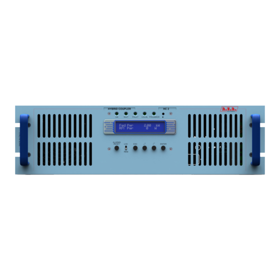
6. Controls, Indicators e Connectors This chapter describes the front and rear panels of the HC2, with a short explanation of the different components, and the pinout of its connectors. 6.1 Front Panel [1] DISPLAY Liquid Cristals Display [2] ON Green LED, lit when the hybrid coupler is switched on. -
Page 24: Rear Panel
6.2 Rear panel [1] VOLTAGE CHANGER & A.C. LINE FUSE Fuse block and Line Voltage Selector. Use a small screwdriver to change the fuse or line voltage. Rotate the block and position it for desired voltage. [2] 24 V External 24 V dc power supply input for CPU backup power supply approx consumption 250mA [3] FUSE Protection Fuse for Auxiliary Out A.C. -
Page 25: Connectors Description
6.3 Connectors Description 6.3.1 Telemetry Connector Type: DB25 Female PIN Signal Type Notes Unbal. Power Ana Out 3.9V x 650 W Ch_4 Disabled Reflected Power Ana Out 4.3V x 100W OC_ECC Dig Out OC Active when interlock is active OC_SET4 Disabled IN_ON Dig In... - Page 26 6.3.3 I C Connector Type: DB9 Female - Used for I C networking Serial Data Serial Clock 22 / 30 Rev. 1.1L - 07/07/03 User Manual...
-
Page 27: Technical Specifications
7. Technical Specifications 7.1 Physical and Environmental Specifications Cabinet Dimensions 447.0 mm x 132.5 mm x 507.5 mm Panel Dimensions 483 mm x 132.5 mm Weight 17.5 Kg -10 °C ÷ 50 °C Operating Temperature Range Humidity 90% Maximum, not condensing 7.2 Electrical Specifications AC power supply 117-230 V, 50-60 Hz... - Page 28 This page was intentionally left blank 24 / 30 Rev. 1.1L - 07/07/03 User Manual...
-
Page 29: Internal Description
8. Internal Description The hybrid coubler HC2 is a modularized device, in which different section are designed to perform a particular function. RF output to Amp 1 RF input from exciter RF output RF Splitter to Amp 2 Telemetry, RS232, Display, Keys Interlock ... -
Page 30: Modules Description
8.2 Modules description 8.2.1 Power supply The power supply of the HC2 uses a mains transformer (70 VA) with selectable voltage primary circuit (110-120-230-240V) and two secondary windings. The first is a 3A 0-16V used to supply the remote card, the second is a 2A 11.5V that gives power to the CPU section. -
Page 31: Adjustment
8.2.5 CPU This subsystem is composed of three parts: the CPU board in itself, the analog section and the interconnection and the EMI filter board. This section implements all the software functions described in the previous part of the manual (measurement, protection, controls, data visualization, communications). - Page 32 two different positions, depending on the machine’s version: directly on the splitter circuit • • on two printed circuits boards that can be accessed from the front panel of the coupler In general, the rightmost capacitors are the ones used to adjust the RF path related to the amplifier connected to the rightmost output connector of the coupler.
- Page 33 Figure 4 Repeat steps 6 and 7 until the transmitter’s power reaches a value that cannot be further rised Increase the exciter power and verify that the system can reach the station’s nominal power 10) Switch off the transmitter 11) Put in place again the coupler’s upper cover Notes: •...
- Page 34 Figure 5 • For each amplifier, two couples of variable capacitors are present: 1,2,3 and 4 for the amplifier “A”, 5,6,7 and 8 for the amplifier “B” (see the silk- graph on the rear of the coupler for reference). • Please remember to use an isolated scrwedriver to adjust the capacitors to avoid misadjustments due to short-circuits.
Need help?
Do you have a question about the HC2 LCD and is the answer not in the manual?
Questions and answers