Table of Contents
Advertisement
Quick Links
Advertisement
Table of Contents

Subscribe to Our Youtube Channel
Related Manuals for R.V.R. Elettronica PJ1000M-C


Summary of Contents for R.V.R. Elettronica PJ1000M-C
- Page 1 PJ2000M-C, PJ2500M-C & PJ3000M-C User Manual Volume 1 Manufactured by Italy...
- Page 2 Monophase and three-phase wiring 09/01/2009 J. H. Berti upgrade PJ2000M-C, PJ2500M-C & PJ3000M-C - User Manual Version 1.5 © Copyright 2003-2009 R.V.R. Elettronica SpA Via del Fonditore 2/2c - 40138 - Bologna (Italia) Telephone: +39 051 6010506 Fax: +39 051 6011104 Email: info@rvr.it Web: www.rvr.it...
-
Page 3: Table Of Contents
PJ2000M-C, PJ2500M-C & PJ3000M-C Table of Contents Preliminary Instructions Warranty First Aid Treatment of electrical shocks Treatment of electrical Burns General Description Make-up Quick installation and operating reference Preparation Operation Software Protection System External Description PS Module Frontal Panel PS module Rear Panel Connector Description RF Module Frontal Panel RF module Rear Panel... - Page 4 PJ2000M-C, PJ2500M-C & PJ3000M-C This page was intentionally left blank Rev. 1.5 - 09/01/09 User Manual...
-
Page 5: Preliminary Instructions
If it is decided to return the that the manufacturer’s instructions are been followed. unit to the factory, R.V.R. Elettronica will mail you a regular authorization with all the necessary instructions to send back the goods;... -
Page 6: First Aid
• If there are two rescuers, the rythm shall be of part number. one brath each 5 compressions. R.V.R. Elettronica SpA • Do not interrupt the rythm of compressions Via del Fonditore, 2/2c when the second person is giving breath. -
Page 7: General Description
PJ2000M-C, PJ2500M-C & PJ3000M-C 4. General Description The PJ3000M-C is an RF amplifier for frequency modulation sound broadcasting with a max. rated output of 3000 watts, for the PJ2500M-C the max. rated output is 2500W while for the PJ2000M-C model the max. rated output is of 2000 watts. They are a fully solid-state apparatus of modern design that use MOSFET as active components in the FM amplifying modules. - Page 8 PJ2000M-C, PJ2500M-C & PJ3000M-C • Detecting the warning thresholds set by the user (e.g. power delivered below a specific threshold), which are made available to the user via the telemetry connector • Communicating with external devices The amplifier’s control software is based on a menu system through which the user may navigate using the following four buttons: ESC, , ed ENTER.
-
Page 9: Quick Installation And Operating Reference
PJ2000M-C, PJ2500M-C & PJ3000M-C 5. Quick installation and operating reference The scope of this chapter is to summarize the procedures for installing the machine. If any point is not fully comprehensible, such as how to operate the machine the first time, it is advisable to read the entire manual very carefully. In this description it is assumed that the amplifier is not supplied pre-installed in a rack inside a transmission system. - Page 10 PJ2000M-C, PJ2500M-C & PJ3000M-C • Data connection by means of cable with DB37 connectors (PS-RF Interconnection) • Ground connection between each module chassis • Power supply connection by means of cable coming out of the PS module ending with the ILME CXM 4/2 type of socket (DC Output) 6 / 40 Rev.
- Page 11 PJ2000M-C, PJ2500M-C & PJ3000M-C Figure 5-1 Example of installation in a rack Connect the output of a suitable type of FM exciter (e.g. the PTXLCD of R.V.R. Elettronica) to the RF input (RF module) using a cable fitted with N type connectors. The exciter should be set to minimum output power and OFF.
-
Page 12: Operation
PJ2000M-C, PJ2500M-C & PJ3000M-C Figure 5-2: View of the mains multipole socket - terminals side (internal) Single-phase power supply: • G Ground • 1 Not connected • 2 Phase • 3 Neutral • 4 Not connected • 11,12 Not connected Danger: avoid the risk of damaging the machine by grounding it correctly. -
Page 13: Software
PJ2000M-C, PJ2500M-C & PJ3000M-C effect it might not be possible to obtain a reading of exactly 3 kW, 2.5 kW or 2 kW, but a lightly higher or lower value which is perfectly normal). Note: now the amplifier is adjusted to its rated output, but the AGC function is not checking the delivered power. - Page 14 PJ2000M-C, PJ2500M-C & PJ3000M-C Switch On Selection Menu ENTER Operation Menu ENTER Power Menu ENTER P.A. Menu ENTER Set Up Menu ENTER Alarm Menu ENTER Miscellaneous Menu ENTER Version Menu Figura: Flow diagram of the software When turned on, the LCD shows the introductory screenful with the equipment’s software and hardware versions.
- Page 15 PJ2000M-C, PJ2500M-C & PJ3000M-C To access one of the submenus select its name (which is underlined by a blinking cursor) using the RIGHT or LEFT keys and then press the ENTER key. Take note that certain parameters, which are measured and shown to the user, might not be available in a few cases.
- Page 16 PJ2000M-C, PJ2500M-C & PJ3000M-C 5.3.3 Power Amplifier Menu (P.A.) This screen, consisting of several lines that may be scrolled through by using the UP and DOWN keys, displays all the measurements associated with the RF amplifier of the equipment: • Voltage (VPA) • Current (IPA) • Efficiency • Temperature...
- Page 17 PJ2000M-C, PJ2500M-C & PJ3000M-C The limit voltages of the quantities monitored by the warning thresholds for are the follows: • Forward Power 3000 W (mod. PJ3000M-C) • Forward Power 2500 W (mod. PJ2500M-C) • Forward Power 2000 W (mod. PJ2000M-C) • Reflected Power 200 W Proceed as follows to change the values of the warning thresholds:...
- Page 18 PJ2000M-C, PJ2500M-C & PJ3000M-C The task of this menu is essentially to help the technician in identifying the possible causes of any malfunction. 5.3.6 Miscellaneous Menu In this menu the user may: • set the address in the serial bus connection, type I •...
-
Page 19: Protection System
PJ2000M-C, PJ2500M-C & PJ3000M-C 5.3.7 Version Menu This screenful shows the hardware version (H.V.) and the software version (S.V.) of the equipment. 5.4 Protection System The protection system implemented inside the amplifier is based on two types of intervention. The first reaction is called “Foldback” and consists in decreasing the voltage in the power amplifier when the forward or reflected power exceeds the proportional limit voltage value. - Page 20 PJ2000M-C, PJ2500M-C & PJ3000M-C The system resets the alarm counters automatically after thirty minutes of operation, i.e. the user need not do anything, if the amplifier does not trigger any alarms or after the machine the machine has been turned OFF and then back ON. 5.4.1 RF module auxiliary protection The amplifier’s RF module contains a second microcontroller that manages local measurements and carries out auxiliary protection functions of the machine...
-
Page 21: External Description
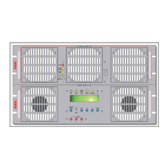
PJ2000M-C, PJ2500M-C & PJ3000M-C 6 External Description This chapter describes the elements presents on the panels of the PJ3000M-C, PJ2500M-C and PJ2000M-C. 6.1 PS Module Frontal Panel [1] AIR FLOW Grill for the ventilation flow passage [2] ON Green LED indicating the amplifier is switched on [3] WAIT Yellow LED indicating the amplifier is waiting for a condition that is blocking the power output to be removed... -
Page 22: Ps Module Rear Panel
PJ2000M-C, PJ2500M-C & PJ3000M-C 6.2 PS module Rear Panel [1] MAINS FUSE Protection fuses of the power supplies 1,2 and 3 [2] MAINS CONNECTOR Plug for mains power supply [3] AIR FLOW Grill for the ventilation flow passage [4] RS232 DB9 connector to interface with external devices or factory programming [5] I... -
Page 23: Connector Description
PJ2000M-C, PJ2500M-C & PJ3000M-C 6.3 Connector Description 6.3.1 Telemetry Connector Type: DB25 Female Internal SWR 3,9V x 1/2W Tensione dell’ amplificatore di potenza RF 3,9V x 50V Reflected Power 4.3V x 200W Interlock Set 4 “On” Command Set 1 WAIT Reset alarm Interlock Temperature... - Page 24 PJ2000M-C, PJ2500M-C & PJ3000M-C 6.3.3 I C Connector Type: DB9 Female Serial Data Serial Clock 6.3.4 Com Bus Type: DB15 male 485+ 485- ON OFF C INP PWR ST BY PWR REG 20 / 40 Rev. 1.5 - 09/10/09 User Manual...
- Page 25 PJ2000M-C, PJ2500M-C & PJ3000M-C 6.3.5 Interconnection PS-RF Type: DB37 female GND, Internally connected with 12/14/15/23/25/26/28/31/33 V TOT R PWR TEMP PS OFF PS REG PWR REG ON OFF CLIX RESET AL GND, Internally connected with 1/14/15/23/25/26/28/31/33 485+ GND, Internally connected with 1/12/15/23/25/26/28/31/33 GND, Internally connected with 1/12/14/23/25/26/28/31/33 AC3, Internally connected with 35 I TOT...
-
Page 26: Rf Module Frontal Panel
PJ2000M-C, PJ2500M-C & PJ3000M-C 6.4 RF Module Frontal Panel [1] AIR FLOW Grill for the ventilation flow passage [2] FAULT Red LED that indicates a fault that cannot be automatically reverted [3] FUSE BLOWN Red LED that indicates the presence of one or more broken fuses [4] RF PWR ADJ Power regulation trimmer - A.G.C. -
Page 27: Rf Module Rear Panel
PJ2000M-C, PJ2500M-C & PJ3000M-C 6.5 RF module Rear Panel [1] INTERCONNECTION PS-RF DB37 connector for interfacement with PS part DB9 connector reserved for future uses [3] RF IN RF input connector (“N” type) [4] RF IN TEST Connector for the drawn not standardized of the modulator input signal [5] PLUG Plug for the supply of 50V... - Page 28 PJ2000M-C, PJ2500M-C & PJ3000M-C 6.5.1 Interconnection PS-RF Type: DB37 female GND, internally connected with 12/14/15/23/25/26/28/31/33 V TOT R PWR TEMP PS OFF PS REG PWR REG ON OFF CLIX RESET AL GND, internally connected with 1/14/15/23/25/26/28/31/33 485+ GND, internally connected with 1/12/15/23/25/26/28/31/33 GND, internally connected with 1/12/14/23/25/26/28/31/33 AC3, internally connected with 35 I TOT...
- Page 29 PJ2000M-C, PJ2500M-C & PJ3000M-C This page was intentionally left blank User Manual Rev. 1.5 - 09/01/09 25 / 40...
- Page 30 PJ2000M-C, PJ2500M-C & PJ3000M-C This page was intentionally left blank 26 / 40 Rev. 1.5 - 09/10/09 User Manual...
- Page 31 PJ2000M-C, PJ2500M-C & PJ3000M-C This page was intentionally left blank User Manual Rev. 1.5 - 09/01/09 27 / 40...
-
Page 32: Operating Theory
PJ2000M-C, PJ2500M-C & PJ3000M-C 8. Operating theory The figure shows the PS and the RF part of amplifier seen from above. The various cards are described in this chapter. • Top View of PS secition with PFC: 1) PS-RF Interface Board SLINPSP2K01 (PJ2000M-C &... - Page 33 PJ2000M-C, PJ2500M-C & PJ3000M-C • Top View of PS section with Rectifier (only PJ2000M-C e PJ2500M-C) 1) PS-RF Inteface board SLINPSP2K01 2) Surge Protection Board SLSRGPRPJ2K1 3) Rectifiers RCTPSL1000 4) Power Supply PSL1000/PJ2K 5) CPU Boards PROTPJ-HCL 6) LEDs Boards SLLEDPSPJ2K2 User Manual Rev.
- Page 34 PJ2000M-C, PJ2500M-C & PJ3000M-C Top View of RF section (mod. PJ3000M-C) • 1) Low-pass Filter Board SLLPFPJ2KLST 2) Amplifier Modules SL046RF1001 3) Fuses Board SLFUSRFPJ4K1 4) Bias Boards SLMTPRTPJ4K1 & CPU Board CPUPJ2KMC 5) LEDs Boards SLLEDRFPJ2K1 30 / 40 Rev.
-
Page 35: Power Supply Change
PJ2000M-C, PJ2500M-C & PJ3000M-C Top view of RF section (mod. PJ2500M-C & PJ2000M-C) • 1) Low-pass Filter Board SLLPFPJ2KLST 2) Amplifier Modules SL042RF1001 (mod. PJ2000M-C) / (SL010RF4001) mod. PJ2500M-C 3) Fuses Board SLFUSRFPJ2K1 4) Bias Boards SLMTPRTPJ2K1 & CPU Board CPUPJ2KMC 5) LEDs Boards SLLEDRFPJ2K1 8.1 Power Supply Change To use the amplifier with different types of power supply you should connect the... - Page 36 PJ2000M-C, PJ2500M-C & PJ3000M-C 8.1.1 Single-Phase Wiring WARNING: the power supply in single-phase can be used only with 208/230V voltage. For the single-phase, the configuration of the external power supply plug must have the following characteristics: • PIN1 of the main connector is connected to Neutral wire. •...
- Page 37 PJ2000M-C, PJ2500M-C & PJ3000M-C 8.1.2 Three-Phase Wiring For the three-phase, the configuration of the external power supply plug must have the following characteristics: • PIN1 of the main connector is connected to Neutral wire. • PIN2 of the main connector is connected to Phase R Wire. •...
- Page 38 PJ2000M-C, PJ2500M-C & PJ3000M-C 8.1.3 Voltage Change WARNING: the single-phase power supply may be used only with 208/230 Volts. Proceed as follows to change voltage inside the machine: • Make the JP3 connection, on the Rectifier card, between PIN 1 and 2 to select 230 Volts, or between PIN 2 and 3 for 115 Volts.
-
Page 39: Ps Part
PJ2000M-C, PJ2500M-C & PJ3000M-C Figure 8-2: Connection for the selection of 115V or 208/230V three fase with neutral wire 8.2 PS Part 8.2.1 Surge Protection This card’s main function is to avoid any damage to the internal cards by blocking the contact before current reaches the equipment in case overvoltages occur. - Page 40 PJ2000M-C, PJ2500M-C & PJ3000M-C The PFC can work with input supply voltages from 90 V to 250 V. A rectified voltage of 350 V is present on the output. In place of PFC units, can be installed “traditional” rectifiers units (without power factor corrector).
-
Page 41: Rf Part
PJ2000M-C, PJ2500M-C & PJ3000M-C 8.3 RF Part 8.3.1 RF Power Amplifier The RF power amplifying section consists in 8 (mod. PJ2000M-C & PJ2500M- C) or 6 (mod. PJ3000M-C) power modules coupled by a Wilkinson splitter and combiner and implemented in strip-line technology. The RF modules, the splitter and the combiner are housed inside the top part of the equipment. - Page 42 PJ2000M-C, PJ2500M-C & PJ3000M-C module, total current and average voltage. 8.3.4 Low-Pass Filter This filter is located at the back of the equipment. The task of the low-pass filter is to reduce the harmonic emissions of the amplifier to below the levels allowed by standards. 8.3.5 Directional Coupler The task of these two cards that seem identical is to supply the power measurement.
-
Page 43: Low-Drive Power" Option (/Ld)
PJ2000M-C, PJ2500M-C & PJ3000M-C 9. “Low-Drive Power” Option (/LD) The figure shown the top view of RF section of the equipment with LD option. The board comes described in the continuation of this chapter. Figure 9-1: “Low-Drive power” Board “Low-Drive power” Board The “Low-Drive power”... - Page 44 PJ2000M-C, PJ2500M-C & PJ3000M-C This page was intentionally left blank 40 / 40 Rev. 1.5 - 09/10/09 User Manual...
Need help?
Do you have a question about the PJ1000M-C and is the answer not in the manual?
Questions and answers