
Related Manuals for R.V.R. Elettronica VJ15000-TR


Summary of Contents for R.V.R. Elettronica VJ15000-TR
- Page 1 Date: 25/07/03 R.V.R. Elettronica S.r.l. (BO) VJ15000-TR - R.F. Tube Amplifier TECHNICAL AND MANTEINANCE MANUAL VJ15000-TR 15KW Power Triode Amplifier 87.5-108 MHz Manufactured by R.V.R. Elettronica - Italy...
-
Page 2: Table Of Contents
Date: 25/07/03 R.V.R. Elettronica S.r.l. (BO) VJ15000-TR - R.F. Tube Amplifier INDEX I - PRELIMINARY INSTRUCTIONS AND WARRANTY INFORMATION............5 II - TUBE WARRANTY INSTRUCTIONS........................7 VARIAN POWER GRID PRODUCT LIMITED WARRANTY.................. 7 III – SAFETY REGULAMENT! ............................ 8 WARNING! ................................. 8 TREATMET OF ELECTRICAL SHOCK ........................ - Page 3 Date: 25/07/03 R.V.R. Elettronica S.r.l. (BO) VJ15000-TR - R.F. Tube Amplifier PICTURES FIG. 1 FRONTAL VIEW ............................14 FIG. 2 REAR VIEW ..............................15 FIG. 3 UPPER VIEW ..............................16 FIG. 4 HINGED FRONTAL PANEL WITH TELEMETRY..................17 FIG. 5 HINGED FRONTAL PANEL WITHOUT TELEMETRY ................
- Page 4 Date: 25/07/03 R.V.R. Elettronica S.r.l. (BO) VJ15000-TR - R.F. Tube Amplifier TABLE D - MEASURE TESTS CARD .......................... 52 TABLE E - QUIESCENT WORKING PARAMETERS....................56 TABLE F - ADVISABLE EQUIPMENT FOR TEST..................... 56 TABLE G - VOLTAGE STABILYZER PARAMETERS....................56...
-
Page 5: I - Preliminary Instructions And Warranty Information
Date: 25/07/03 R.V.R. Elettronica S.r.l. (BO) VJ15000-TR - R.F. Tube Amplifier I - PRELIMINARY INSTRUCTIONS AND WARRANTY INFORMATION Please observe safety precautions when handling this unit. This equipment contains dangerous currents and high voltages. This manual is written as a general guide for those having previous knowledge and experience with this kind of equipment. - Page 6 Date: 25/07/03 R.V.R. Elettronica S.r.l. (BO) VJ15000-TR - R.F. Tube Amplifier To claim your rights under this warranty: Contact the dealer or distributor where you prchased the unit. Describe the problem and ask if he has an easy solution. Dealers and Distributors are supplied with all the information about problems that may occur and usually they can repair the unit quicker than what the manufacturer could do.
-
Page 7: Ii - Tube Warranty Instructions
Date: 25/07/03 R.V.R. Elettronica S.r.l. (BO) VJ15000-TR - R.F. Tube Amplifier II - TUBE WARRANTY INSTRUCTIONS VARIAN POWER GRID PRODUCT LIMITED WARRANTY Varian products are warranted to be free from defects in workmanship and materials only. The warranty involves both calendar time and filament (or heather) operation time. -
Page 8: Iii - Safety Regulament
The installation, operation, maintenance and service of this equipment involves risks both to personnel and equipment, and must be performed only by qualified personnel exercising due care. R.V.R. ELETTRONICA s.r.l. shall not be responsible for injury or damage resulting from improper procedures or from the use of improperly trained or inexperienced personnel performing such tasks. -
Page 9: Treatmet Of Electrical Shock
Date: 25/07/03 R.V.R. Elettronica S.r.l. (BO) VJ15000-TR - R.F. Tube Amplifier In case of emergency ensure that power has been disconnected. TREATMET OF ELECTRICAL SHOCK 1) If victim is not responsive follow the A-B-C's of basic life support. PLACE VICTIM FLAT ON HIS BACK ON A HARD SURFACE... - Page 10 Date: 25/07/03 R.V.R. Elettronica S.r.l. (BO) VJ15000-TR - R.F. Tube Amplifier c. Loosen their clothing (a reclining position is recommended).
-
Page 11: First-Aid
Date: 25/07/03 R.V.R. Elettronica S.r.l. (BO) VJ15000-TR - R.F. Tube Amplifier FIRST-AID Personnel engaged in the installation, operation, maintenance or servicing of this equipment are urged to become familiar with first-aid theory and practices. The following information is not intended to be a complete first-aid procedure, it is brief and is only to be used as a reference. -
Page 12: Chapter 1
VJ15000-TR GENERAL DESCRIPTION MECHANICAL DESCRIPTION The VJ15000-TR is allocated in a 19" rack, 40H, 7 of which are free and can be used to insert an exciter, a receiver or any other equipment. Two analog instruments are placed on FIG. 1 the hinged frontal panel ( ) with all other controls and commands. -
Page 13: Chapter 2
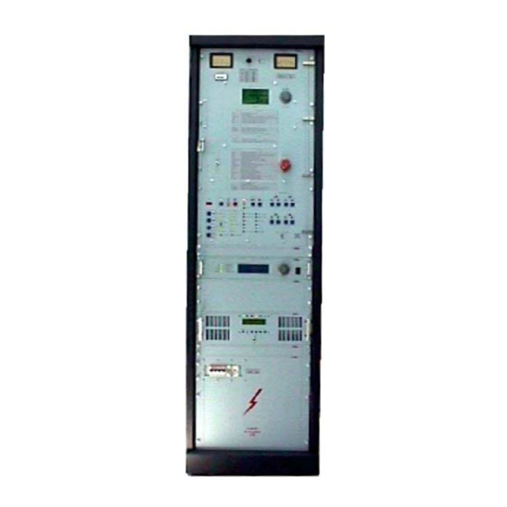
-10° to +50°C Umidity max 90%, Without condensing CHAPTER 2 ELECTRICAL DESCRIPTION INTRODUCTION This chapter describes accurately the VJ15000-TR electrical components. For an easy understanding, the equipment is been divided in modules, each of them is described completely as follows. - Page 14 Date: 25/07/03 R.V.R. Elettronica S.r.l. (BO) VJ15000-TR - R.F. Tube Amplifier FIG. 1 FRONTAL VIEW REF. DESCRIPTION Protections panel (18U) Exciter (2U) Driver (3H) High Voltage Panel (9H) Free panel (1HE) Free panel (3HE ) Free panel (2HE) Free panel (2HE)
- Page 15 Date: 25/07/03 R.V.R. Elettronica S.r.l. (BO) VJ15000-TR - R.F. Tube Amplifier FIG. 2 REAR VIEW REF. DESCRIPTION Rear panel Air filter...
- Page 16 Date: 25/07/03 R.V.R. Elettronica S.r.l. (BO) VJ15000-TR - R.F. Tube Amplifier FIG. 3 UPPER VIEW REF. DESCRIPTION RF output connector (1+5/8") Output air chimney Upper panel...
- Page 17 Date: 25/07/03 R.V.R. Elettronica S.r.l. (BO) VJ15000-TR - R.F. Tube Amplifier FIG. 4 HINGED FRONTAL PANEL WITH TELEMETRY...
- Page 18 Date: 25/07/03 R.V.R. Elettronica S.r.l. (BO) VJ15000-TR - R.F. Tube Amplifier REF. DESCRIPTION MULTIMETER: Analog instrument for the measures of temperature, filament voltage and current, anode voltage and current and grid voltage. VOLTAGES SELECTOR: Voltages selector for the measures of the following.
- Page 19 Date: 25/07/03 R.V.R. Elettronica S.r.l. (BO) VJ15000-TR - R.F. Tube Amplifier FIG. 5 HINGED FRONTAL PANEL WITHOUT TELEMETRY...
- Page 20 Date: 25/07/03 R.V.R. Elettronica S.r.l. (BO) VJ15000-TR - R.F. Tube Amplifier FIG. 6 HIGH VOLTAGE PANEL REF. DESCRIPTION Quadripole main switch Service outlet.
- Page 21 Date: 25/07/03 R.V.R. Elettronica S.r.l. (BO) VJ15000-TR - R.F. Tube Amplifier FIG. 7 P1 POWER SUPPLY SECTION VIEW REF. DESCRIPTION Rectifier diodes bridge for plate voltage. Plate voltage power supply transformer. Plate Voltage transformer socket. Plate voltage filtering capacitor. Inductance.
- Page 22 Date: 25/07/03 R.V.R. Elettronica S.r.l. (BO) VJ15000-TR - R.F. Tube Amplifier FIG. 8 P2 POWER SUPPLY SECTION VIEW REF. DESCRIPTION Tuning relays card. Power relays card. Filament solenoid switch 1. Filament solenoid switch 2. Blower solenoid switch. High tension solenoid switch 1.
- Page 23 Date: 25/07/03 R.V.R. Elettronica S.r.l. (BO) VJ15000-TR - R.F. Tube Amplifier LEFT VIEW (PARTICULAR) POWER SUPPLY SECTION...
- Page 24 Date: 25/07/03 R.V.R. Elettronica S.r.l. (BO) VJ15000-TR - R.F. Tube Amplifier FIG. 9 R.F. CAVITY FRONTAL VIEW REF. DESCRIPTION Threaded bar for motorized tuning. Sliding plane with fingers. Plate pipe. Wrapper. Plate ring. Wrapper. Blower air input. Load capacitor.
- Page 25 Date: 25/07/03 R.V.R. Elettronica S.r.l. (BO) VJ15000-TR - R.F. Tube Amplifier FIG. 10 R.F. CAVITY FRONTAL VIEW REF. DESCRIPTION Plate ring. Tube Socket filament contact. Tube Socket filament contact. Load capacitor.
- Page 26 Date: 25/07/03 R.V.R. Elettronica S.r.l. (BO) VJ15000-TR - R.F. Tube Amplifier FIG. 11 TUNING MOTORIZED MECHANISM VIEW RIGHT PARTICULAR VIEW TUNING SWITCHS RIF. DESCRIZIONE H.T. cable. Plate pipe isolator. Horn gap arrester. Micro switch for R.F. cavity protection. Plate pipe.
- Page 27 Date: 25/07/03 R.V.R. Elettronica S.r.l. (BO) VJ15000-TR - R.F. Tube Amplifier Micro switch for upper end position of the sliding plane. T.A. FIG. 12 R.F. CAVITY TOP VIEW RIF. DESCRIZIONE EIA 1+5/8" flange (R.F. output connector). Wattmeter. Directional coupler. Output air chimney (diameter 180 mm).
- Page 28 Date: 25/07/03 R.V.R. Elettronica S.r.l. (BO) VJ15000-TR - R.F. Tube Amplifier FIG. 13 R.F. CAVITY LEFT LATERAL VIEW VIEW DISSASEMBLED STRIPLINE RIF. DESCRIZIONE Power supply plane. Finger. Stripline. Cavity RF. Low pass filter. Cavity input air. Electro mechanical plane.
- Page 29 Date: 25/07/03 R.V.R. Elettronica S.r.l. (BO) VJ15000-TR - R.F. Tube Amplifier FIG. 14 R.F. CAVITY RIGHT LATERAL VIEW RIF. DESCRIZIONE Cavity Rf view. Low pass filter view. Power sypply section Electro mechanical plane. Power switchs for tuning motors.
- Page 30 Date: 25/07/03 R.V.R. Elettronica S.r.l. (BO) VJ15000-TR - R.F. Tube Amplifier FIG. 15 REAR VIEW RIF. DESCRIZIONE Blower. Power supply plane. Power transformer support. Electro mechanical plane. Low pass filter. Service calmps.
-
Page 31: Chapter 3
Date: 25/07/03 R.V.R. Elettronica S.r.l. (BO) VJ15000-TR - R.F. Tube Amplifier CHAPTER 3 EQUIPMENT INSTALLATION INTRODUCTION This chapter contains the necessary information for the installation and the preliminary checks of the VJ15000-TR amplifier. UNPACKING Remove the equipment from its packing, Verify that the unit that isn’t damaged during the transport. - Page 32 Date: 25/07/03 R.V.R. Elettronica S.r.l. (BO) VJ15000-TR - R.F. Tube Amplifier MAIN TRANSFORMER SUPPORT SCREWS Once inserted the cart to the inside, to pass on the anterior part and to get off the plexiglass of protection and to lace the threads to the terminal board protection and to lace the threads of the terminal board (see drawings) with: n°...
-
Page 33: Tube Installation
Date: 25/07/03 R.V.R. Elettronica S.r.l. (BO) VJ15000-TR - R.F. Tube Amplifier TUBE INSTALLATION For the tube installation is necessary to execute the following procedure: Connect the power supply cable in the relative socket paying attention to exact position of the phases and neutral. The mains voltage must be the same for that is been set the equipment (see as reference the test control card). - Page 34 Date: 25/07/03 R.V.R. Elettronica S.r.l. (BO) VJ15000-TR - R.F. Tube Amplifier FIG. 16 TUBE INSTALLATION DIAGRAM N°1...
- Page 35 Date: 25/07/03 R.V.R. Elettronica S.r.l. (BO) VJ15000-TR - R.F. Tube Amplifier FIG. 17 TUBE INSTALLATION DIAGRAM N°2...
- Page 36 Date: 25/07/03 R.V.R. Elettronica S.r.l. (BO) VJ15000-TR - R.F. Tube Amplifier FIG. 18 TUBE INSTALLATION REFERENCE VIEW N°2...
- Page 37 Date: 25/07/03 R.V.R. Elettronica S.r.l. (BO) VJ15000-TR - R.F. Tube Amplifier FIG. 19 TUBE INSTALLATION DIAGRAM N°3...
- Page 38 Date: 25/07/03 R.V.R. Elettronica S.r.l. (BO) VJ15000-TR - R.F. Tube Amplifier FIG. 20 TUBE INSTALLATION REFERENCE VIEW N°3 PARTICOLARE MORSETTO...
- Page 39 Date: 25/07/03 R.V.R. Elettronica S.r.l. (BO) VJ15000-TR - R.F. Tube Amplifier FIG. 21 TUBE INSTALLATION REFERENCE VIEW N°4...
- Page 40 Date: 25/07/03 R.V.R. Elettronica S.r.l. (BO) VJ15000-TR - R.F. Tube Amplifier FIG. 22 TUBE INSTALLATION REFERENCE VIEW N°4...
- Page 41 Date: 25/07/03 R.V.R. Elettronica S.r.l. (BO) VJ15000-TR - R.F. Tube Amplifier See for reference distance above tuning adjusting. (the distance correspondly to the MHz) FIG. 23 REGULATION RF - MHZ Height Cm Frequence (Mhz) 10.5 11.5 12.5 13.5 14.5 15.5 16.5...
-
Page 42: Equipment Setting At Work
Date: 25/07/03 R.V.R. Elettronica S.r.l. (BO) VJ15000-TR - R.F. Tube Amplifier EQUIPMENT SETTING AT WORK To set at work the amplifier VJ15000 it’s necessary to execute the following operations: The equipment is set for a mains voltage of 380 Vac (other on request), three phases with neutral. - Page 43 Date: 25/07/03 R.V.R. Elettronica S.r.l. (BO) VJ15000-TR - R.F. Tube Amplifier Increase the driving power and then execute a new adjustment through the OUPUT TUNE and OUPUT LOAD commands until you have the maximum exciter output power. Using only the modulator is possible to reach an output power of 600-700 W (with 3CX15000A7).
-
Page 44: Chapter 4
Date: 25/07/03 R.V.R. Elettronica S.r.l. (BO) VJ15000-TR - R.F. Tube Amplifier CHAPTER 4 TUBE MEASURES CARD CALIBRATION NOTICE Pay attention, this calibration is been executed initially on the final power amplifier during the checking test, only in case of card replacement, after that is been verified that is the cause of the equipment anomaly, is necessary to proceed to the calibration of the card as described later on. - Page 45 Date: 25/07/03 R.V.R. Elettronica S.r.l. (BO) VJ15000-TR - R.F. Tube Amplifier FIG. 24 MEASURES CARD REFERENCE VIEW...
- Page 46 Date: 25/07/03 R.V.R. Elettronica S.r.l. (BO) VJ15000-TR - R.F. Tube Amplifier FIG. 25 MEASURES CARD REPLACING DIAGRAM N°1...
- Page 47 Date: 25/07/03 R.V.R. Elettronica S.r.l. (BO) VJ15000-TR - R.F. Tube Amplifier FIG. 26 MEASURES CARD REPLACING DIAGRAM N°2...
-
Page 48: Measures Card Adjusting Operations
VJ15000-TR - R.F. Tube Amplifier Before to proceed, check the test resistors values in according to the amplifier type that is used (in this case the type is VJ15000-TR that uses 3CX15000A7 tube, see as reference TABLE D FIG. 39 Since, the protections intervention on the equipment is set at 3.9 V, is necessary that at... - Page 49 Date: 25/07/03 R.V.R. Elettronica S.r.l. (BO) VJ15000-TR - R.F. Tube Amplifier Now, it’s necessary calibrate the voltage value nearest to zero using the following trimmers: P1 for VF P5 for IG1 P2 for IF P6 for VG1 P3 for VA...
- Page 50 Date: 25/07/03 R.V.R. Elettronica S.r.l. (BO) VJ15000-TR - R.F. Tube Amplifier In this manual is furnished the jumpers position for the 3CX15000A7 tube installed on the VJ15000-TR Once finished the previous operations it’s necessary to connect a power supply with an...
- Page 51 Date: 25/07/03 R.V.R. Elettronica S.r.l. (BO) VJ15000-TR - R.F. Tube Amplifier FIG. 27 POWER SUPPLIES CONNECTION FOR THE CALIBRATION OF TEST POINT VOLTAGES...
-
Page 52: Table D - Measure Tests Card
Date: 25/07/03 R.V.R. Elettronica S.r.l. (BO) VJ15000-TR - R.F. Tube Amplifier TABLE D - MEASURE TESTS CARD Model VJ15000-TR Volt Fil. Current Fil. I° STEP input 3,9 VAC 1,665 107,0 mV II° STEP input 6,250 VAC 1,775 171,0 mV 249 mV... - Page 53 Date: 25/07/03 R.V.R. Elettronica S.r.l. (BO) VJ15000-TR - R.F. Tube Amplifier Another possibility to check it, if the protection logic works correctly, is that to generate an justable voltage of 3.95 V by trimmer P20 and to measure it on test point TP10.
- Page 54 Date: 25/07/03 R.V.R. Elettronica S.r.l. (BO) VJ15000-TR - R.F. Tube Amplifier The calibration of the filament voltage and current cannot be executed with power supply, because the measures must be executed in alternate voltage. To calibrate the filament voltage is necessary to apply on CN7 sockets a voltage like as that of the tube (for example with 3CX15000A7 is necessary a voltage of 6.3V) and through trimmer P17...
- Page 55 Date: 25/07/03 R.V.R. Elettronica S.r.l. (BO) VJ15000-TR - R.F. Tube Amplifier FIG. 28 REPORT MEASURE...
-
Page 56: Table E - Quiescent Working Parameters
Date: 25/07/03 R.V.R. Elettronica S.r.l. (BO) VJ15000-TR - R.F. Tube Amplifier TABLE E - QUIESCENT WORKING PARAMETERS PARAMETER 3CX15000A7 Anode Current 400-600 mA Filament Current 160 A Filament Voltage 6.3 ± 0.37V Grid 1 Voltage Automatic polarization Anode Voltage 7500 V... -
Page 57: Chapter 5
Date: 25/07/03 R.V.R. Elettronica S.r.l. (BO) VJ15000-TR - R.F. Tube Amplifier CHAPTER 5 MAINTENANCE SAFETY RULES PAY ATTENTION ! PAY ATTENTION ! PAY ATTENTION ! PAY ATTENTION ! When the amplifier is working on, and the rear panel is been removed, inside of equipment are present dangerous high tensions. -
Page 58: Tube Replacing
Date: 25/07/03 R.V.R. Elettronica S.r.l. (BO) VJ15000-TR - R.F. Tube Amplifier TUBE REPLACING Through the command Ouput tune, move the sliding plane with fingers until the upper end position (threshold bars completely exctracted).. Disconnect the mains voltage from equipment. Verify that the tube that must be replaced is cold sufficiently to avoid very serious burns. -
Page 59: Chapter 6
Date: 25/07/03 R.V.R. Elettronica S.r.l. (BO) VJ15000-TR - R.F. Tube Amplifier CHAPTER 6 ADJUSTMENTS NOTE: THESE OPERATIONS MUST BE EXECUTED BY VERY QUALIFIED TECHNICIANS AND EQUIPPED WITH NECESSARY INSTRUMENTS. UNCORRECTED OPERATIONS CAN CUASE A SERIOUS DAMAGE OF THE EQUIPMENT AND CAUSE AUTOMATICALLY THE RESOLVING OF THE WARRANTY. - Page 60 Date: 25/07/03 R.V.R. Elettronica S.r.l. (BO) VJ15000-TR - R.F. Tube Amplifier This section contains circuit diagrams and alyouts of the module which conposing the equipment FIG. 29 POWER SUPPLY SOCKET...
- Page 61 Date: 25/07/03 R.V.R. Elettronica S.r.l. (BO) VJ15000-TR - R.F. Tube Amplifier FIG. 30 ANODE TENSION TRANSFORMER SOCKET...
- Page 62 Date: 25/07/03 R.V.R. Elettronica S.r.l. (BO) VJ15000-TR - R.F. Tube Amplifier FIG. 31 RACK POWER SUPPLY BASE...
- Page 63 Date: 25/07/03 R.V.R. Elettronica S.r.l. (BO) VJ15000-TR - R.F. Tube Amplifier FIG. 32 HIGH TENSION PANEL...
- Page 64 Date: 25/07/03 R.V.R. Elettronica S.r.l. (BO) VJ15000-TR - R.F. Tube Amplifier FIG. 33 ELECTROMECHANICAL PLANE (TRIODE)
- Page 65 Date: 25/07/03 R.V.R. Elettronica S.r.l. (BO) VJ15000-TR - R.F. Tube Amplifier...
- Page 66 Date: 25/07/03 R.V.R. Elettronica S.r.l. (BO) VJ15000-TR - R.F. Tube Amplifier...
- Page 67 Date: 25/07/03 R.V.R. Elettronica S.r.l. (BO) VJ15000-TR - R.F. Tube Amplifier FIG. 34 RESISTENZE DI SOFT-START E POLARIZZAZIONE VALVOLA...
- Page 68 Date: 25/07/03 R.V.R. Elettronica S.r.l. (BO) VJ15000-TR - R.F. Tube Amplifier FIG. 35 TUBE AMPLIFIERS PROTECTIONS CARD...
- Page 69 Date: 25/07/03 R.V.R. Elettronica S.r.l. (BO) VJ15000-TR - R.F. Tube Amplifier FIG. 36 HIGH POWER RELAYS CARD...
- Page 70 Date: 25/07/03 R.V.R. Elettronica S.r.l. (BO) VJ15000-TR - R.F. Tube Amplifier FIG. 37 TUNING RELAYS CARD...
- Page 71 Date: 25/07/03 R.V.R. Elettronica S.r.l. (BO) VJ15000-TR - R.F. Tube Amplifier FIG. 38 TELEMETRY INTERFACE CARD...
- Page 72 Date: 25/07/03 R.V.R. Elettronica S.r.l. (BO) VJ15000-TR - R.F. Tube Amplifier FIG. 39 MEASURES CALIBRATION CARD...
- Page 73 Date: 25/07/03 R.V.R. Elettronica S.r.l. (BO) VJ15000-TR - R.F. Tube Amplifier FIG. 40 THERMAL STROBE CONNECTOR...
- Page 74 Date: 25/07/03 R.V.R. Elettronica S.r.l. (BO) VJ15000-TR - R.F. Tube Amplifier FIG. 41 P.W.R. MEASURE CONNECTOR...
- Page 75 Date: 25/07/03 R.V.R. Elettronica S.r.l. (BO) VJ15000-TR - R.F. Tube Amplifier FIG. 42 I2 CBUS CONNECTOR FOR TELEMETRY BOX...
- Page 76 Date: 25/07/03 R.V.R. Elettronica S.r.l. (BO) VJ15000-TR - R.F. Tube Amplifier FIG. 43 PTXLCD CONNECTOR...
- Page 77 Date: 25/07/03 R.V.R. Elettronica S.r.l. (BO) VJ15000-TR - R.F. Tube Amplifier FIG. 44 LOW VOLTAGE CIRCUIT DIAGRAM...
- Page 78 Date: 25/07/03 R.V.R. Elettronica S.r.l. (BO) VJ15000-TR - R.F. Tube Amplifier FIG. 45 THREE-PHASES CIRCUIT DIAGRAM...
- Page 79 Date: 25/07/03 R.V.R. Elettronica S.r.l. (BO) VJ15000-TR - R.F. Tube Amplifier FIG. 46 MEASURES AND ALLARMS CIRCUIT DIAGRAM...
- Page 80 Date: 25/07/03 R.V.R. Elettronica S.r.l. (BO) VJ15000-TR - R.F. Tube Amplifier FIG. 47 ELECTRIC SCHEMES...
- Page 81 Date: 25/07/03 R.V.R. Elettronica S.r.l. (BO) VJ15000-TR - R.F. Tube Amplifier © Copyright 2001 R.V.R. Elettronica S.p.a. (Bo) Via del Fonditore 2/2c - 40138 - Bologna (Italy) Telephone: + 39 - 51 - 6010506 Fax: + 39 - 51 - 6011104 e-mail: info@rvr.it...
- Page 82 Date: 25/07/03 R.V.R. Elettronica S.r.l. (BO) VJ15000-TR - R.F. Tube Amplifier or by any information storage and retrieval system, without permission in writing from the publisher.
Need help?
Do you have a question about the VJ15000-TR and is the answer not in the manual?
Questions and answers